


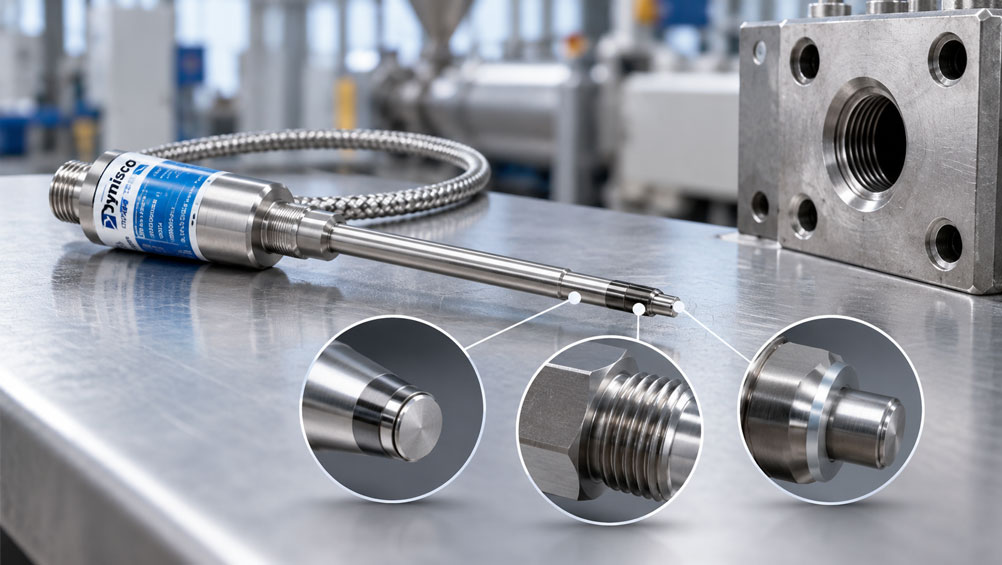
A Dynisco melt pressure sensor is removed from the extruder during maintenance. At first glance, the sensor still appears complete and the electrical signal was normal before removal. Can it simply be cleaned and screwed back in?
In principle, many melt pressure sensors can be reused after removal. Before reinstalling the sensor, however, it should be checked for damage caused by removal, polymer deposits, mechanical loading or previous operating conditions.
The very thin process diaphragm at the sensor tip, the process thread and the sealing or seating surface are particularly critical. Even minor damage can affect pressure transmission, installation position or the mechanical loading of the diaphragm.
The mounting hole itself is equally important. Even a technically flawless sensor can be damaged during reinstallation if hardened polymer remains inside the bore, the thread is damaged or the intended sealing surface is no longer clean and geometrically correct.
Before reuse, the complete combination of sensor and mounting hole should therefore always be assessed: diaphragm, sensor tip, thread, sealing surface, stem, electrical function and mounting bore must all be suitable for reinstallation.
Why does successful reuse already begin during removal?
Whether a melt pressure sensor can be reused depends not only on its previous operating condition. The removal process itself can also damage the sensor.
The following components are particularly vulnerable:
- the thin pressure diaphragm,
- the sensor tip,
- the process thread,
- the rigid sensor stem,
- any flexible capillary that may be present.
If a sensor becomes tilted, is turned using the wrong component or is pulled out of solidified polymer, a previously functional sensor can be damaged during removal.
The assessment for reuse therefore already begins with controlled removal.
Why should the sensor not be pulled out of solidified polymer?
During extrusion, the diaphragm is located directly at or within the melt channel.
After cooling, polymer can adhere to the sensor tip and especially to the diaphragm.
If the sensor is then mechanically pulled out of the cold, solidified material, high tensile and shear forces can act on the diaphragm.
Possible consequences include:
- deformed diaphragm,
- torn diaphragm,
- detached diaphragm,
- damaged sensor tip.
Dynisco therefore recommends removing the sensor while the polymer is still sufficiently soft or molten.
The system must, of course, be in the safe maintenance condition specified for the equipment. Temperature, pressure and mechanical hazards must be controlled in accordance with the operating and safety instructions.
How should the diaphragm be assessed after removal?
The diaphragm is the most sensitive mechanical component of the melt pressure sensor.
After removal, it should be visually inspected under good lighting.
Check, for example, for:
- dents,
- waves or wrinkles,
- scratches,
- indentations around the edge,
- adhering hardened polymer,
- visible cracks,
- a partially or completely missing diaphragm.
An intact diaphragm should not be mechanically loaded with tools in an attempt to “test” its elasticity.
Never press the diaphragm with a screwdriver, measuring probe or any other hard object.
Even an apparently minor mechanical deformation can affect pressure transmission and the sensor zero point.
How may the sensor tip be cleaned?
Polymer residues should preferably be removed while they are still soft or deformable.
The sensitive diaphragm requires gentle, non-abrasive cleaning.
Depending on the sensor version and manufacturer instructions, a suitable soft cloth may be used, for example.
During cleaning:
- no high pressure must be applied to the diaphragm,
- the diaphragm must not be scraped,
- the sensor tip must not be subjected to lateral forces.
The objective is simply to remove soft material residues carefully.
If polymer is already firmly bonded to the diaphragm, it should not be removed by mechanical force.
Which cleaning methods can damage the sensor?
The diaphragm of a melt pressure sensor is not a robust machine component that can be cleaned in the same way as an extruder screw.
Particularly problematic methods include:
- screwdrivers,
- steel wire brushes,
- abrasives,
- files,
- hard scrapers,
- uncontrolled blasting,
- open flames or burners.
In particular, a sensor should not be heated with a burner to melt hardened polymer off the diaphragm.
Extreme localized temperatures can damage the sensor filling, diaphragm, joints and internal components.
When cleaning the extruder itself, the pressure sensors should also be removed beforehand if abrasive cleaning methods are used.
How should the process thread be inspected?
After removal, the thread should be completely cleaned and then visually inspected.
Typical abnormalities include:
- flattened thread turns,
- raised material,
- galling marks,
- worn thread flanks,
- polymer residues in the thread,
- signs of previous cross-threading or misalignment.
A damaged thread can prevent the sensor from being guided axially into the mounting hole during reinstallation.
This can subject the sensor tip to lateral loading.
A sensor must therefore not be forced into a tight process thread using increased torque.
If the sensor cannot be screwed in cleanly and without cross-threading, the cause must first be identified.
Why is the sealing surface so important?
In typical Dynisco mounting holes, the process seal is not provided by the thread alone.
A defined seating or sealing surface ensures that the sensor is correctly positioned and sealed against the melt.
For the common 1/2-20 UNF connection, the mounting hole has a defined 45° seating surface.
Before reinstalling the sensor, check that:
- the corresponding sensor surface is undamaged,
- no polymer residues remain on the seating surface,
- there are no burrs,
- there are no obvious pressure marks or galling marks.
A damaged seating surface can result in:
- the sensor not sealing correctly,
- a changed installation depth,
- mechanical stress on the sensor tip.
The sealing surface is therefore just as important as the thread.
What should be checked on the sensor stem and capillary?
On sensors such as the Dynisco PT462, a flexible capillary is located between the rigid sensor stem and the housing.
This area should also be inspected after removal.
Check for:
- a straight rigid sensor stem,
- no kinks,
- no visible crushed areas,
- no overstretched flexible capillary,
- no unusually tight bend radii,
- no mechanical damage at the connection to the housing.
A flexible capillary must not be used as a handle for unscrewing or carrying the sensor.
The sensor housing itself should also not be used to apply installation or removal torque.
Why must the mounting hole also be checked?
Even a completely intact sensor can be damaged immediately during reinstallation if the mounting hole is not clean.
After the sensor is removed, melt can enter the open sensor bore and cool there.
During later installation, the sensor tip may then come into contact with hardened polymer.
Possible consequences include:
- an indented diaphragm,
- lateral loading of the sensor tip,
- incorrect installation depth,
- insufficient seating on the sealing surface.
The mounting hole should therefore be free from interfering material residues before every reinstallation.
The following areas should be checked particularly carefully:
- thread,
- sensor tip bore,
- 45° seating surface,
- bore depth.
However, overly aggressive repeated cleaning can also be problematic because it can alter the geometry of the mounting hole.
When is a gauge plug useful?
If installation problems occur repeatedly or before reinstalling a valuable sensor, a suitable gauge plug can be used to inspect the mounting hole.
The gauge plug reproduces the critical installation geometry of the sensor.
This allows you to check whether:
- the thread is clear,
- the sensor tip bore has sufficient clearance,
- the intended sealing surface seats correctly,
- no interfering polymer residues remain.
For the common 1/2-20 UNF connection, Dynisco offers the gauge plug 200908, for example.
It is also included in the Dynisco Cleaning Tool Kit 200100.
Corresponding tool kits are available for other sensor connections.
When should high-temperature anti-seize be used?
For Dynisco connections designed for this purpose, a suitable high-temperature anti-seize compound may be applied to the thread.
This can reduce the risk of the thread seizing at high process temperatures.
The compound should be applied only to the specified thread surface in accordance with the manufacturer instructions.
It must not be allowed to contaminate:
- the diaphragm,
- the sensor tip or
- the sealing surface.
Chemical compatibility with the process and application must also be taken into account.
Why is the correct tightening torque important?
A melt pressure sensor must be seated firmly enough, but it must not be mechanically overloaded by unnecessarily high torque.
The specified torque is applied at the designated hexagon on the sensor.
The following should not be used as points for applying installation torque:
- sensor housing,
- connector,
- flexible capillary.
Excessive torque can:
- damage the thread,
- load the sensor stem,
- generate mechanical stress,
- make later removal more difficult.
The correct tightening torque is specific to the sensor and connection and must be taken from the relevant Dynisco operating instructions.
Electrical checks before and after reinstallation
A diaphragm that appears visually intact does not automatically mean that the sensor remains electrically and metrologically unchanged.
Before reinstallation or recommissioning, the electrical function should therefore also be checked.
Depending on the sensor and available equipment, the following can be checked, for example:
- zero signal,
- signal stability,
- excitation voltage,
- insulation condition or electrical connections,
- internal shunt calibration function, if available.
The Dynisco PT462, for example, provides an internal shunt calibration function.
This is useful for checking the electrical signal path, but it does not replace a mechanical pressure calibration of the sensor.
After reinstallation, the zero point should also be checked under the conditions specified for the sensor.
An unusually large zero shift can indicate that the sensor is mechanically stressed or already damaged.
How should a removed sensor be stored?
A removed sensor should not be left unprotected among tools on a workbench.
The diaphragm tip in particular must be protected against mechanical contact.
Recommended precautions include:
- a suitable protective cap on the sensor tip,
- clean, dry storage,
- no loading of the flexible capillary,
- no heavy components placed on top of the sensor,
- no contact between the diaphragm and tools or work surfaces.
Dynisco recommends protecting the sensor-tip or diaphragm side after removal.
Even a functional spare sensor can be irreparably damaged simply by being stored incorrectly.
When should a sensor no longer be reinstalled?
Reuse should be critically assessed or ruled out if, for example:
- the diaphragm is torn or visibly deformed,
- part of the diaphragm is missing,
- the sensor sealing surface is severely damaged,
- the process thread shows significant galling or deformation,
- the sensor stem is bent,
- the flexible capillary is kinked or damaged,
- the electrical signal is implausible or unstable,
- significant mechanical overload is suspected.
A damaged diaphragm should not be straightened, ground or pushed back into shape on site.
If there is any doubt, a technical inspection or repair assessment by a suitable service provider is preferable to risky reinstallation.
Practical example: reinstalling the sensor after a tooling change
An extruder is shut down for a tooling change. The installed Dynisco melt pressure sensor is to be reused afterwards.
The sensor is removed while the remaining polymer is still sufficiently soft.
After removal, the following is found:
- diaphragm visually undeformed,
- no visible scratches,
- thread free from galling,
- sealing surface clean,
- sensor stem straight,
- capillary free from kinks.
Soft polymer residues are carefully removed and the sensor tip is then stored with suitable protection.
Before reinstallation, the mounting hole is cleaned.
The appropriate gauge plug is used to verify that the sensor tip bore is clear and that the intended sealing surface seats correctly.
Only then is the sensor reinstalled.
After the system has been heated up, the electrical zero point is checked and the signal is monitored while the process is restarted in a controlled manner.
This inspection before reinstallation prevents a functional sensor from being destroyed during its second installation by hardened polymer or a damaged mounting hole.
Systematic inspection procedure before reinstallation
- Bring the system into the specified safe maintenance condition.
- Keep the polymer sufficiently soft or molten.
- Remove the sensor using the designated hexagon.
- Do not apply force through the housing or capillary.
- Carefully remove soft polymer residues.
- Inspect the diaphragm under good lighting.
- Inspect the sensor tip and sealing surface.
- Check the process thread for damage.
- Inspect the sensor stem and capillary.
- Protect the sensor until reinstallation.
- Clean the mounting hole.
- Inspect the thread and 45° sealing surface of the bore.
- Use a gauge plug if required.
- Apply only the specified anti-seize to the thread.
- Screw in the sensor without cross-threading.
- Observe the specified tightening torque.
- Check the zero point and electrical signal.
- Monitor the measured value when restarting the system.
Common mistakes
- Pulling the sensor out of cold, solidified polymer: Adhering material can damage or tear off the diaphragm.
- Cleaning the diaphragm with a screwdriver: The thin process diaphragm can be deformed even by relatively small mechanical forces.
- Using a wire brush: Abrasive tools can damage the diaphragm and sealing surfaces.
- Removing polymer with a burner: Local overheating can damage the sensor internally.
- Checking only the sensor: A contaminated or damaged mounting hole can destroy an intact sensor during reinstallation.
- Overcoming thread damage with higher torque: This can cause cross-threading and lateral loading of the sensor tip.
- Ignoring the sealing surface: Correct installation position does not depend on the thread alone.
- Using the capillary to unscrew the sensor: The flexible connection is not designed for torsional loading.
- Leaving the sensor unprotected: The diaphragm can already be damaged by contact with tools or the workbench.
- Applying anti-seize to the diaphragm or sealing surface: Lubricant belongs only on the specified thread surface.
- Restarting production immediately after reinstallation: Zero point and signal should first be checked for plausibility.
- Interpreting shunt calibration as complete pressure calibration: It mainly checks the electrical signal path and does not replace a pressure reference.
Dynisco PT462 and suitable installation accessories
A typical melt pressure sensor for extrusion applications is the Dynisco PT462.
The series features a rigid sensor stem with a flexible capillary and, depending on the version, is available with:
1/2-20 UNF-2AorM18 × 1.5
as the process connection.
The maximum specified diaphragm temperature is 400 °C. The PT462 output signal is 3.33 mV/V; an internal 80 % shunt calibration is also available.
Dynisco offers suitable accessories for installation and maintenance.
The Cleaning Tool Kit 200100, for example, is intended for the common 1/2-20 UNF mounting hole. It can be used to clean the sensor tip bore, thread and 45° seating surface in a controlled manner.
The tool kit also includes a gauge plug. Gauge Plug 200908 is also available separately and is used to check the relevant bore geometry.
Corresponding tool kits are available for other connection sizes.
Further information can be found under Dynisco PT462 melt pressure sensor, under Dynisco sensor accessories and under Dynisco products at ICS Schneider.
Conclusion
A removed Dynisco melt pressure sensor can generally be reused if its mechanical and electrical condition remains satisfactory.
Particular attention must be paid to the process diaphragm. It is very thin and must not be mechanically stressed during removal or cleaning. The sensor should therefore be removed while the polymer is sufficiently soft and any material residues should then be removed carefully.
The thread and sealing surface must also be inspected. A damaged thread can cause the sensor to cross-thread during reinstallation, while a contaminated or damaged seating surface can lead to incorrect positioning or mechanical loading.
The mounting hole is equally important. Hardened polymer, burrs or damaged geometry can destroy a technically sound sensor during reinstallation.
A suitable cleaning tool and gauge plug can be used to clean and inspect the mounting hole in a controlled manner.
After installation, the electrical behaviour and zero point should also be checked. Internal shunt calibration is useful for checking the signal path, but does not replace a complete pressure calibration.
For safe reuse, the following therefore applies: remove the sensor in a controlled manner at a suitable process temperature, do not mechanically work on the diaphragm, inspect the thread and sealing surface, clean and check the mounting hole, reinstall the sensor using the correct torque and verify zero point and signal plausibility before releasing the system for production.
FAQ: Reusing a Dynisco sensor after removal
Can a Dynisco melt pressure sensor be reused after removal?
Yes, provided that the diaphragm, sensor tip, thread, sealing surface, stem and electrical function remain intact and the mounting hole is suitable for reinstallation.
Why should a Dynisco sensor not be removed cold?
Solidified polymer can adhere to the diaphragm. Pulling the sensor out can then generate high mechanical forces that deform or tear off the diaphragm.
How may the diaphragm be cleaned?
Material residues should preferably be removed while they are still soft. Cleaning must be gentle and non-abrasive in accordance with the manufacturer instructions.
Can I use a screwdriver to remove polymer from the diaphragm?
No. Hard tools can damage the thin diaphragm even with relatively low mechanical force.
Can a Dynisco sensor be cleaned with a wire brush?
The sensitive sensor and diaphragm side should not be treated with abrasive or hard cleaning tools.
Can hardened polymer be removed with a burner?
This is not recommended. Extreme local heating can damage the diaphragm, sensor filling and internal components.
What should be checked on the thread?
Check for galling, deformed thread turns, material residues and indications that the sensor was cross-threaded during previous installation or removal.
Why is the sealing surface important?
It defines the correct seating of the sensor and affects both sealing and installation position. Contamination or damage can lead to incorrect positioning and mechanical loading of the sensor tip.
Does the mounting hole need to be cleaned before reinstallation?
Yes. Hardened polymer in the sensor-tip bore or on the sealing surface can damage the diaphragm when the sensor is screwed in.
What is a gauge plug?
A gauge plug reproduces the relevant sensor or mounting geometry and can be used to check the thread, clearance and sealing surface of the cleaned mounting hole.
Which gauge plug is used for the common 1/2-20 UNF connection?
Dynisco offers Gauge Plug 200908 for this purpose, for example. It is also included in Cleaning Tool Kit 200100.
Should anti-seize be used during reinstallation?
For sensors designed for it, a suitable high-temperature anti-seize compound may be applied to the thread in accordance with the manufacturer instructions to reduce the risk of seizing. The diaphragm and sealing surface must not be contaminated.
Can internal shunt calibration confirm that the diaphragm is mechanically intact?
No. Electrical shunt calibration primarily checks the electrical measurement and signal path. It cannot reliably rule out mechanical damage to the diaphragm.
Which Dynisco sensor is suitable as an example for this maintenance case?
A typical example is the Dynisco PT462 with rigid sensor stem and flexible capillary. It is designed for melt pressure applications with diaphragm temperatures up to 400 °C and is available with 1/2-20 UNF-2A or M18 × 1.5 process connections.