


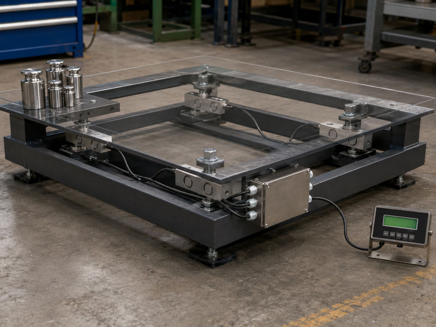
A platform scale displays exactly:
200.0 kg
when a test weight is placed in the center.
However, when the same weight is placed successively in the four corners, the following values may be displayed, for example:
Corner 1: 199.6 kg
Corner 2: 200.2 kg
Corner 3: 199.9 kg
Corner 4: 200.1 kg
The zero point and central calibration can therefore be correct while the scale displays different values depending on the position of the load.
On a platform with four load cells, the total signal is generated from the signals of all four transducers. Differences in mechanical load distribution, load cell sensitivity or force introduction can cause the same test load to produce different results at different positions on the platform.
Corner load adjustment must not be used to conceal mechanical faults. First, the platform, supports, load cell installation and force path must be checked. Only once the mechanical setup is correct should any remaining electrical signal differences be balanced via the summing box or junction box.
For a conventional four-load-cell setup, for example, the WIKA B6578 Junction Box is suitable. It combines up to four passive mV/V signals and allows the connected load cells to be individually trimmed. Suitable shear beam load cells for platform and floor scales include the WIKA F3201. Further solutions can be found under Load Cells at ICS Schneider.
For the mechanical design, the technical article Installing Load Cells Correctly: Avoiding Incorrect Force Introduction, Support Errors and Force Shunts is also relevant.
Table of Contents
- How a platform scale with four load cells works
- What is a corner load error?
- Distinguishing mechanical and electrical causes
- Why the actual load distribution is not always 25% per load cell
- Check the mechanics before electrical adjustment
- Purpose of the summing box
- Considering differences in load cell sensitivity
- Performing the corner load test correctly
- Determining the correct reference corner
- Electrically trimming the load cells
- Why the center load must be checked again afterwards
- Do not confuse corner load adjustment with calibration
- Practical example of a four-cell platform
- Force shunts as a common source of error
- Platform rigidity and leveling
- Load cell cables and wiring errors
- What to consider after replacing a load cell
- Documenting the corner load test
- Typical error patterns
- Systematic adjustment in practice
- Suitable weighing technology from ICS Schneider
- Conclusion
- FAQ
How a platform scale with four load cells works
On larger platform and floor scales, one load cell is typically installed at each corner or at each defined support point.
In simplified form, the system consists of:
Load cell 1 + load cell 2 + load cell 3 + load cell 4 → summing box → weighing electronics
The individual load cells usually operate with a strain gauge full bridge and provide a load-dependent signal in the range of:
mV/V
The summing box combines the four signals into one common output signal.
With a centrally applied load
the weight force is distributed approximately over all four supports.
With an ideally symmetrical platform, for example:
Total load 1,000 kg → approximately 250 kg per load cell
In a real design, however, this distribution is rarely exactly equal.
What is a corner load error?
A corner load error, or an error under eccentric loading, occurs when the same load produces different displayed values depending on its position on the platform.
Example
| Position | Display with the same test load |
|---|---|
| Center | 200.0 kg |
| Corner 1 | 199.6 kg |
| Corner 2 | 200.2 kg |
| Corner 3 | 199.9 kg |
| Corner 4 | 200.1 kg |
The greatest difference between the corners in this example is:
200.2 kg − 199.6 kg = 0.6 kg
The problem is not necessarily detectable during central calibration.
A scale can display the correct value with a centered load and still show a significant error under off-center loading.
Distinguishing mechanical and electrical causes
A corner load error can generally originate from two areas:
| Mechanical cause | Electrical cause |
|---|---|
| uneven mounting surface | different load cell sensitivities |
| stressed or distorted platform frame | tolerances in the mV/V signals |
| lateral forces | different cable resistances |
| force shunts | faulty terminals |
| incorrect force introduction | different sensor parameters |
| load cell not fully loaded | damaged or drifting load cell |
The troubleshooting sequence is crucial
A summing box can compensate for small differences between the sensor signals.
However, it cannot reliably correct situations where, for example:
- one corner of the platform is mechanically binding,
- one load cell is partially unloaded,
- a pipe or cable supports the platform,
- a load cell is subjected to an inclined load.
Heavy electrical trimming with incorrect mechanics may improve one specific test condition, but it often leads to poor linearity, repeatability or long-term stability.
Why the actual load distribution is not always 25% per load cell
Four load cells do not automatically mean that each load cell always carries exactly one quarter of the total load.
The load distribution depends, among other things, on:
- position of the load,
- rigidity of the platform,
- position of the load cells,
- height tolerances of the supports,
- deformation of the frame,
- floor levelness.
With a corner load
the load cell closest to the load is subjected to a significantly higher load than the load cell at the opposite corner.
This is exactly why the corner load test is suitable for revealing differences between the four measuring chains.
A certain amount of unequal force distribution is normal by design
The purpose of the adjustment is not to make all four load cells carry exactly the same force at every load position.
The objective is:
Regardless of where the same load is positioned, the summed weighing signal should produce as nearly as possible the same weight value.
Check the mechanics before electrical adjustment
Before opening the summing box, the mechanical setup should first be checked.
1. Check the scale unloaded
The platform must rest freely on its intended weighing points.
It must not contact:
- protective covers,
- stops,
- ramps,
- pipes,
- cable ducts.
2. All four load cells must be loaded
A simple check may be to inspect the load response or mechanical play at each support point.
If, for example, a platform rests stably on only three support points and the fourth load cell only becomes loaded at higher loads, electrical corner load adjustment is not the correct solution.
3. Check mounting surfaces
The support surfaces must be:
- flat,
- clean,
- load-bearing,
- aligned according to the sensor specifications.
4. Check force introduction
With shear beam load cells, the load must be applied in the intended direction.
The WIKA F3201, for example, is intended for platform and floor scales. For correct measurement, a flat support surface and force introduction that is as centered and free from transverse forces as possible are important.
Purpose of the summing box
A summing box or junction box combines the signals of several load cells.
For a four-cell system, in simplified form:
Stotal = S1 + S2 + S3 + S4
The summed signal is then forwarded to:
- weighing indicator,
- measuring amplifier,
- weighing electronics,
- PLC weighing module.
A summing box with trimming capability goes one step further
The individual sensor channels can be adjusted slightly so that differences between the four weighing points are reduced.
The WIKA B6578 processes up to four passive mV/V signals and provides four individually assignable trim adjustments for this purpose.
Considering differences in load cell sensitivity
Even four load cells of the same type have manufacturing tolerances.
For example, one load cell may provide at rated load:
2.0000 mV/V
another:
2.0030 mV/V
and another:
1.9985 mV/V
The values are very close to one another, but they are not identical.
With a centered load, such differences can partially compensate for one another
However, if the test load is positioned directly above one corner, the load cell at that location contributes a significantly larger proportion of the total signal.
The difference in sensitivity then becomes visible as a corner load deviation.
This is exactly where electrical corner load adjustment is used
The channels with the higher sensitivity are adjusted to a common reference value.
Performing the corner load test correctly
For reproducible adjustment, the same test load must be placed successively at defined positions.
Preparation
- Fully assemble the scale mechanically.
- Level the scale or align it according to the manufacturer’s instructions.
- Allow the electronics to stabilize sufficiently.
- Set the zero point.
- Perform a basic calibration.
- Use a suitable and known test load.
The four test positions must be clearly defined
For example:
Corner 1 → Corner 2 → Corner 3 → Corner 4
The load should be positioned as reproducibly as possible at the same relative location at each corner.
The test load must be sufficiently large
A very small load can make differences caused by:
- display resolution,
- zero drift,
- friction,
- mechanical hysteresis
difficult to identify clearly.
The specific test load depends on the size of the scale, measuring range, resolution and, where applicable, relevant manufacturer or legal metrology requirements.
Determining the correct reference corner
With the WIKA B6578, the corner with the lowest displayed value is used as the reference or base corner after the corner load test.
Example
| Corner | Display |
|---|---|
| 1 | 199.6 kg |
| 2 | 200.2 kg |
| 3 | 199.9 kg |
| 4 | 200.1 kg |
Therefore:
Corner 1 = base corner
The remaining channels are adjusted to this corner.
Why use the lowest value?
With conventional resistive trimming, the higher sensor signals are attenuated.
A signal that is already lower can therefore be used as the common reference by attenuating the other channels.
Electrically trimming the load cells
On the WIKA B6578, the four sensor channels are assigned to the potentiometers:
W1 / W2 / W3 / W4
Practical procedure
- Place the test load on corner 1 and record the display.
- Place the same load on corner 2 and record the display.
- Repeat the test at corner 3.
- Repeat the test at corner 4.
- Define the corner with the lowest value as the base corner.
- Reduce the higher corner values using the corresponding channel.
- Move the test load through all four corners again.
- Repeat the adjustment until the values agree sufficiently.
For the B6578
Adjusting the corresponding potentiometer changes the signal contribution of the respective sensor channel.
According to the manufacturer:
Turn clockwise → attenuate signal
and:
Turn counterclockwise → increase signal
.
Adjustment should be carried out gradually.
After each change, the test load is repositioned and the result is checked again.
Why the center load must be checked again afterwards
Trimming changes the contribution of individual load cells to the total signal.
As a result, the overall display with a centrally applied load can also change slightly.
After corner load adjustment, therefore, the following must be checked again
Place the test weight in the center of the platform and check:
- zero point,
- displayed value of the test weight,
- additional calibration points where necessary.
If the central display is then, for example:
199.5 kg instead of 200.0 kg
the span of the weighing electronics must be recalibrated.
Corner load adjustment and span calibration influence one another. Therefore, trimming must always be followed by another overall check.
Do not confuse corner load adjustment with calibration
The two procedures have different objectives.
| Procedure | Objective |
|---|---|
| Zero adjustment | Set the unloaded scale to zero |
| Span calibration | Assign the display to a known weight |
| Corner load adjustment | Minimize position-dependent differences |
| Linearity test | Check several load points across the measuring range |
| Repeatability test | Check variation under repeated identical loading |
A platform scale can therefore be:
correctly calibrated + poorly balanced
or:
well balanced + incorrectly calibrated
.
For a reliable weighing system, both properties must be correct.
Practical example of a four-cell platform
An industrial platform scale has four load cells and a weighing range of:
0 … 1,000 kg
A suitable test load is used for the corner load test.
Initial measurement
| Position | Display | Deviation from lowest corner |
|---|---|---|
| Corner 1 | 199.6 kg | 0.0 kg |
| Corner 2 | 200.2 kg | +0.6 kg |
| Corner 3 | 199.9 kg | +0.3 kg |
| Corner 4 | 200.1 kg | +0.5 kg |
Corner 1 is used as the base corner.
Adjustment
The channels for corners 2, 3 and 4 are gradually attenuated in the summing box.
After several control runs, the following values may be achieved, for example:
| Position | Display after trimming |
|---|---|
| Corner 1 | 199.6 kg |
| Corner 2 | 199.6 kg |
| Corner 3 | 199.7 kg |
| Corner 4 | 199.6 kg |
The test load is then positioned in the center again
The overall span is recalibrated if necessary.
The following sequence is then repeated:
Center → Corner 1 → Corner 2 → Corner 3 → Corner 4 → Center
This checks whether the improvement is reproducible.
Force shunts as a common source of error
One of the most important mechanical causes of corner load errors is force shunting.
A force shunt occurs when part of the load is transferred to the foundation without passing through the intended load cells.
Typical examples
- The platform contacts the machine frame at the side.
- A ramp is rigidly in contact with the weighing platform.
- A cable bundle is routed too tightly.
- A hose supports the moving platform.
- A mechanical stop is permanently in contact.
- Dirt has accumulated between the platform and the foundation.
Particularly problematic
A force shunt can act differently depending on the load position.
A load on the left side of the platform may deform the frame differently from the same load on the right side.
This can create an apparent load cell error even though the sensors themselves are electrically functioning perfectly.
Such an error must be corrected mechanically and must not be compensated for using the trim potentiometers.
Platform rigidity and leveling
The design of the platform also influences corner load errors.
A sufficiently rigid platform
distributes loads reproducibly across the four support points.
An excessively flexible structure, on the other hand, can deform differently depending on the position of the load.
Unevenness is also critical
If the four support points are not positioned in a defined plane, one load cell may be mechanically preloaded or partially unloaded.
Before adjustment, therefore, the following should be checked:
- foundation or floor,
- mounting plates,
- load cell height,
- force introduction components,
- platform frame.
Load cell cables and wiring errors
With mV/V signals, the measuring chain operates with very small voltages.
Clean electrical installation is therefore important.
The following should be checked in particular
- correct assignment of the four load cells,
- EXC+/EXC− or excitation voltage,
- SIG+/SIG− or measuring signal,
- sense lines in 6-wire systems,
- shield connection,
- terminal tightness,
- damage to the connection cables.
The assignment of the corners must be unambiguous
If load cell 1 is mechanically installed at corner 1 but connected to channel 3 in the summing box, trimming may affect the wrong corner.
This makes adjustment unnecessarily complicated or practically impossible.
What to consider after replacing a load cell
If a single load cell is replaced, the corner load characteristics may change.
Even a replacement load cell of the same type and rated load has its own individual characteristics.
After replacing a load cell, at least the following should be checked
- zero point,
- corner load,
- span,
- repeatability.
A previous trim setting of the summing box is not automatically correct for the new load cell.
Before retrimming
it should first be checked whether:
- the new load cell has been installed correctly,
- rated load and characteristic value are suitable,
- force introduction and installation height are correct,
- the connection cable is wired correctly.
Documenting the corner load test
During commissioning, maintenance and quality assurance, the corner load adjustment should be documented in a traceable manner.
Useful information includes
- scale designation and serial number,
- load cell types and serial numbers,
- summing box or junction box,
- test load used,
- positions of the four corners,
- measured values before adjustment,
- measured values after adjustment,
- central reference value,
- subsequent calibration,
- date and person performing the work.
This makes it possible during later maintenance to determine whether the load distribution or the behavior of an individual load cell has changed.
Typical error patterns
| Observation | Possible cause | Recommended check |
|---|---|---|
| One corner consistently displays too high | higher sensitivity of this channel | check corner test and trimming |
| One corner displays significantly too low | mechanical unloading or sensor problem | check force introduction and load cell |
| Corner error changes after every loading cycle | mechanical friction or stress | check frame and supports |
| Three corners agree, one differs significantly | individual load cell, installation or wiring issue | investigate affected channel separately |
| After trimming, the corners agree but the center load does not | overall span changed by trimming | repeat span calibration |
| Adjustment affects the wrong corner | load cell channels swapped | check assignment J1 … J4 |
| Scale reading changes abruptly when load approaches one corner | force shunt or stop contact | check platform clearance |
| Corner load error occurs only at high load | frame deformation or mechanical contact | observe platform under load |
| One corner is incorrect after load cell replacement | new sensor characteristic or installation deviation | repeat complete corner load adjustment |
| Value drifts when the cable is moved | cable or terminal problem | check connection and cable |
Systematic adjustment in practice
- Fully assemble the scale: Establish the final mechanical condition.
- Ensure the platform is free: Eliminate force shunts, stops and contacts.
- Check foundation and supports: All four load cells must be loaded in a defined manner.
- Check force introduction: Minimize lateral and transverse forces.
- Check wiring: Clearly assign each load cell to its summing channel.
- Stabilize the electronics: Switch on the weighing electronics and allow them to thermally stabilize.
- Set zero: Set the unloaded platform to zero.
- Perform basic calibration: Carry out an initial span calibration with a known test load.
- Place the test load on corner 1: Document the measured value.
- Check corners 2 to 4: Always use the same load and comparable positioning.
- Determine the lowest corner value: Use this as the base corner.
- Trim the other channels: Gradually match higher signals to the base corner.
- Check all four corners again: Repeat adjustment iteratively.
- Place the test load in the center: Check the overall display.
- Correct the span calibration: Recalibrate if necessary.
- Repeat the corner test again: Ensure that the adjustment remains correct.
- Check additional load points: Evaluate linearity and repeatability.
- Document the results: Record before/after values and settings.
Suitable weighing technology from ICS Schneider
WIKA B6578 Junction Box for Four Load Cells
The WIKA B6578 is particularly suitable for a four-cell weighing system.
It is designed for:
- up to four load cells or force transducers,
- passive mV/V signals,
- parallel connection of the sensors,
- summation to one common output signal,
- individual trimming of the individual sensors.
Individual sensor adjustment in particular enables electrical corner load balancing after the mechanical setup has been checked.
WIKA F3201 Shear Beam Load Cell
The WIKA F3201 is suitable, among other applications, for platform and floor scales.
ICS specifies:
- measuring ranges from 500 to 2,000 kg,
- OIML R60 class C with 3,000 divisions,
- stainless steel,
- hermetically welded design,
- IP68 and IP69K,
- mV/V output signal.
For a four-cell system, the rated load and mechanical design are selected so that each cell remains within its permissible range even under unfavorable load distribution and dynamic load components.
Siemens SIWAREX WL230 SB-S SA as an alternative
For industrial platform scales, the SIWAREX WL230 SB-S SA is also available.
The shear beam load cell is intended for vessel, overhead conveyor and platform scales and is available in different rated loads.
Further sensors, mounting components and junction boxes can be found under Load Cells at ICS Schneider and under Load Cell Accessories.
Conclusion
A platform scale with four load cells must not only be calibrated correctly, but also checked for position-dependent load deviations.
The corner load test always uses the same test load
It is placed successively at defined positions above the four weighing points.
Different readings can have mechanical or electrical causes
Troubleshooting therefore always begins with the platform, supports and force introduction.
Mechanical errors must not be trimmed away
Force shunts, mechanical stress or a partially unloaded load cell must be corrected mechanically.
Remaining electrical differences can be corrected using a summing box
With the WIKA B6578, the four load cell signals can be individually trimmed.
The lowest corner is used as the reference
The higher signal contributions are gradually adjusted to this value.
After corner load adjustment, the overall span must be checked again
Trimming changes the summed signal and may therefore require recalibration.
For practical applications
Check the mechanics → eliminate force shunts → clearly assign the four load cells and channels → perform zero and basic calibration → place the same test load successively on all four corners → determine the lowest corner → trim the higher channels → repeat the corner load test → position the test load in the center → check or recalibrate the overall span → repeat the corner load test → document the results.
FAQ: Corner Load on Platform Scales with Four Load Cells
What is a corner load error?
A corner load error occurs when the same load produces different displayed values depending on its position on the platform.
Why does a corner load error occur?
Possible causes include different load cell sensitivities, mechanical stress, uneven supports, force shunts or installation errors.
Do four load cells have to be loaded exactly equally?
No. Load distribution depends on the position of the load and the design of the platform. What matters is that the summed display remains correct regardless of load position.
What is a summing box?
A summing box or junction box combines the mV/V signals of several load cells into one common output signal.
Can a summing box correct corner load errors?
Yes, if it allows individual trimming of the sensor channels. Mechanically caused errors should, however, first be corrected mechanically.
What does trimming a load cell mean?
Trimming means slightly adjusting the signal contribution of an individual load cell channel in order to compensate for differences between several weighing points.
Which corner is used as the reference during adjustment?
With the WIKA B6578, the corner with the lowest displayed value is used as the base corner. The remaining corners are adjusted to this value.
Why is the highest corner not used as the reference?
With conventional resistive trimming, the higher signal contributions can be attenuated and adjusted to the lower reference value.
How do I check the corner load?
The same test load is placed successively at four defined positions close to the respective weighing points, and the display at each position is documented.
Does the scale have to be calibrated before the corner load test?
A basic calibration is useful so that the corner values can be compared directly. After final trimming, the overall span must be checked again and recalibrated if necessary.
Why does the center load change after trimming?
Because trimming changes the contribution of individual load cells to the summed overall signal.
Can I simply compensate for mechanical errors using the summing box?
This is not recommended. A stressed platform or force shunt may change with load, temperature or position and therefore cannot be permanently corrected by electrical adjustment.
What is a force shunt?
A force shunt occurs when part of the load being measured is transferred to the foundation without passing through the intended load cells.
Can a tightly routed cable cause a measurement error?
Yes. On sensitive platforms, a mechanically stressed cable can exert additional force on the weighing structure.
Why does the platform need to be rigid?
A sufficiently rigid platform ensures reproducible load transfer to the weighing points. Excessive deformation can cause position-dependent errors.
What happens if one load cell is hardly loaded?
The mechanics must first be corrected. A platform should rest in a defined manner on all intended weighing points.
Do I need to check the corner load again after replacing a load cell?
Yes. Even a load cell of the same type has its own characteristics and may require renewed adjustment.
Can I mix different load cell types in a four-cell system?
For a precise weighing system, rated load, characteristic value, excitation voltage, electrical properties and mechanical design should be compatible. Randomly mixing different sensors is not advisable.
What does the WIKA B6578 do?
The B6578 connects up to four passive mV/V load cells in parallel, sums their signals and allows individual trimming of the sensor channels.
How many load cells can be connected to the B6578?
Up to four load cells or force transducers.
Which load cell is suitable for an industrial platform scale?
Depending on the load range and mechanical design, a shear beam load cell such as the WIKA F3201 or the Siemens SIWAREX WL230 SB-S SA can be used.
Is a single-point load cell the same as a four-cell system?
No. A single-point load cell is designed to support a platform using one sensor. Larger platform scales, on the other hand, often use several load cells at separate support points.
Where can I find the WIKA B6578 at ICS Schneider?
Further information is available under WIKA B6578 Junction Box at ICS Schneider.
Where can I find suitable shear beam load cells?
An overview is available under Shear Beam Load Cells at ICS Schneider.
Where can I find further load cell accessories?
Further junction boxes, mounting components and accessories can be found under Load Cell Accessories at ICS Schneider.