


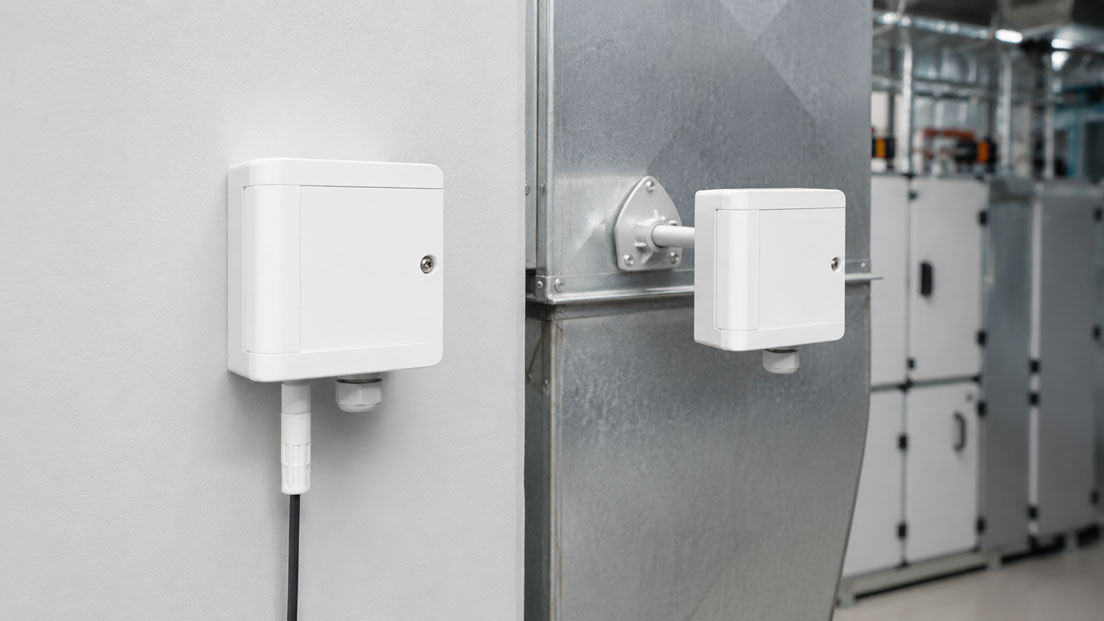
Humidity sensors in ventilation systems, plant rooms and buildings often measure not only relative humidity but also temperature. These measured values must then be transmitted to a PLC, DDC controller or building management system.
Different output signals are available for this purpose. A 4–20 mA output transmits a measured value as a robust analogue current signal. A 0–10 V output is widely used in building services and can be connected easily to many controllers. Modbus RTU, by contrast, transmits several measured and status values digitally via a shared bus.
The decision should not be based solely on selecting the most modern signal. The existing building automation system, number of required measured values, cable length, interference environment, diagnostic requirements and the expertise of future service personnel are decisive.
Table of Contents
- Which values should the humidity sensor transmit?
- Direct comparison of 4–20 mA, 0–10 V and Modbus
- How does a 4–20 mA output work?
- When is 0–10 V appropriate?
- How does Modbus RTU work with humidity sensors?
- Transmitting humidity, temperature and dew point together
- Scaling analogue signals correctly
- Checking the supply voltage and load resistance
- Considering cable length and the interference environment
- Setting up the RS-485 bus correctly
- Comparing diagnostic capabilities
- Failure behaviour and system availability
- Connection to PLC, DDC and building management systems
- Commissioning analogue humidity sensors
- Commissioning Modbus sensors
- Testing a 4–20 mA current loop
- Testing the sensor value and signal transmission separately
- Typical selection and connection errors
- Practical example: Humidity monitoring in a ventilation system
- Decision guide for selecting the signal
- Information required for instrument selection
- Which products are suitable?
- Conclusion
- Frequently asked questions
Which values should the humidity sensor transmit?
Before selecting the output signal, it must be established which measured variables are actually required by the building automation system.
Depending on the version, a combined temperature and humidity sensor can provide values including:
- relative humidity in % RH,
- temperature in °C,
- dew-point temperature,
- absolute humidity,
- enthalpy or other calculated climatic variables,
- sensor status and diagnostic information,
- limit or alarm conditions.
With an analogue output, a separate output is normally required for each continuous measured variable. If humidity and temperature are to be transmitted via 4–20 mA, two current loops and two analogue inputs are therefore usually required.
Modbus can transmit several measured values from one sensor via the same data cable. This is particularly useful when the dew point, status or diagnostic values are required in addition to humidity and temperature.
Direct comparison of 4–20 mA, 0–10 V and Modbus
| Criterion | 4–20 mA | 0–10 V | Modbus RTU |
|---|---|---|---|
| Signal type | Analogue current signal | Analogue voltage signal | Digital communication via RS-485 |
| Measured values per connection | Normally one measured value per loop | Normally one measured value per output | Several measured and status values possible |
| Wiring | Separate cable or input for each signal | Separate cable or input for each signal | Several devices can share one bus |
| Interference immunity | Well suited to industrial environments and longer cable routes | Suitable for many building applications; reference potential must be considered | Good with a professionally installed bus, suitable cable and potential equalisation |
| Diagnostics | Limited to current value and, where applicable, fault current | Limited to voltage value | Additional status, fault and device information possible |
| Commissioning | Easy to measure and simulate | Easy to test with a voltmeter | Address, baud rate, parity and registers must match |
| Expandability | An additional measured value requires an additional input | An additional measured value requires an additional input | Additional devices can be integrated into the bus |
| Typical application | Industry, longer cable routes and existing analogue inputs | HVAC, room automation and compact DDC systems | New building automation systems, many measuring points and several measured values |
How does a 4–20 mA output work?
With a 4–20 mA output, the measured value is transmitted as an electrical current. The lower range value corresponds to 4 mA and the upper range value to 20 mA.
Example for relative humidity:
- 0 % RH corresponds to 4 mA,
- 50 % RH corresponds to 12 mA,
- 100 % RH corresponds to 20 mA.
Within the permissible loop conditions, the measuring current is largely unaffected by the voltage drop along the cable. This makes a current loop attractive for longer cable routes and electrically demanding environments.
The so-called live zero at 4 mA provides another practical advantage. A value of 0 % RH is not transmitted as 0 mA. A complete loss of current can therefore be distinguished from a valid lower measured value.
Depending on the instrument, currents below or above the normal measuring range may be used as fault or overrange signals. The exact meaning must be defined in the data sheet and PLC programming.
When is 0–10 V appropriate?
0–10 V is widely used in HVAC controllers, DDC systems, room automation and control-panel construction. Many building automation systems are equipped with suitable voltage inputs as standard.
Advantages include:
- simple wiring,
- easy testing with a voltmeter,
- widespread use in building automation,
- low equipment requirements for short and clearly arranged cable routes,
- direct compatibility with many controllers and actuators.
With voltage signals, however, the common reference potential and possible voltage drops must be considered. Potential differences between the sensor and controller can influence the displayed measured value.
The controller input resistance must also be compatible with the sensor output. If several inputs are connected in parallel to one output without approval, the output can be overloaded and the signal distorted.
0–10 V is therefore particularly appropriate when:
- the existing building automation system is designed for it,
- the cable length is manageable,
- the sensor and controller are supplied from the same power supply or a defined potential system,
- extensive diagnostic values are not required.
How does Modbus RTU work with humidity sensors?
Modbus RTU is a serial communication protocol that is frequently transmitted via an RS-485 interface in field devices.
The sensor provides its measured values in defined registers. The higher-level controller or a gateway polls these registers regularly.
The following normally have to be defined for each device:
- unique bus address,
- baud rate,
- parity,
- number of stop bits,
- register addresses,
- data type and byte order,
- scaling factor and unit.
One register may contain the humidity value, another the temperature and another the device status. Whether a value is transmitted as an integer, signed value or floating-point number depends on the device.
The statement “the sensor has Modbus” is therefore not sufficient for complete planning. The building automation system also requires the associated register table and communication parameters.
Transmitting humidity, temperature and dew point together
The simultaneous transmission of several values is one of the most important advantages of a digital interface.
With an analogue solution, a combined sensor could be configured as follows:
- output 1: 4–20 mA for 0–100 % RH,
- output 2: 4–20 mA for 0–50 °C,
- two cables or current loops,
- two analogue inputs in the building automation system.
With Modbus, humidity, temperature, dew point and device status can be read via the same bus connection. This reduces the number of analogue inputs and individual signal cables required.
The digital solution is particularly advantageous when:
- many combined sensors are installed,
- several climatic variables are required,
- diagnostic and status values are to be evaluated,
- parameters are to be changed or read centrally,
- the data are also to be archived or visualised.
If only one humidity value is required and the existing controller already has spare analogue inputs, an analogue solution may nevertheless be simpler and more economical.
Scaling analogue signals correctly
The PLC or building management system must know which physical measuring range corresponds to the electrical signal.
The following applies to a 4–20 mA signal:
Measured value = range start + ((current − 4 mA) / 16 mA) × measuring span
Example for 0–100 % RH:
| Current | Scaled value | Humidity |
|---|---|---|
| 4 mA | 0 % | 0 % RH |
| 8 mA | 25 % | 25 % RH |
| 12 mA | 50 % | 50 % RH |
| 16 mA | 75 % | 75 % RH |
| 20 mA | 100 % | 100 % RH |
For a 0–10 V signal with a range of 0–100 % RH, 5 V corresponds to a humidity value of 50 % RH.
Typical scaling errors occur when:
- the PLC is configured for a different measuring range from the sensor,
- the humidity and temperature channels have been interchanged,
- 0–10 V and 2–10 V are confused,
- 0–20 mA is selected instead of 4–20 mA,
- the percentage value and physical value are scaled twice,
- the units °C and °F are confused.
Checking the supply voltage and load resistance
In a 4–20 mA measuring circuit, the power supply must be sufficient for the sensor, the controller input resistance and the voltage drop across the cables.
The available voltage is distributed across:
- the minimum operating voltage of the humidity transmitter,
- the voltage drop across the analogue input,
- the cable resistance,
- isolation amplifiers or surge protection,
- other components within the current loop.
If the available voltage is too low or the total load resistance is too high, the transmitter may no longer reach the upper signal value reliably. A typical symptom is a current that remains significantly below 20 mA despite high humidity.
During planning, it must also be established whether the sensor output is active or passive:
- Active output: The sensor supplies the measuring current itself.
- Passive output: An external loop power supply is required.
If two active sources are connected against each other or a passive loop has no power supply, the measuring circuit will not function correctly.
Considering cable length and the interference environment
The permissible cable length cannot be determined solely from the signal type. It depends, among other factors, on:
- cable cross-section,
- loop power supply and load resistance,
- Modbus baud rate,
- cable quality and shielding,
- potential differences,
- electromagnetic environment,
- cable route and proximity to power cables,
- manufacturer specifications.
For longer cable routes, a 4–20 mA signal is frequently easier to implement than a voltage signal. However, the additional cable resistance increases the required loop voltage.
With 0–10 V, voltage drops and potential shifts can directly affect the measured value. Signal cables should therefore not be routed together with motor or frequency-converter cables.
Modbus over RS-485 is suitable for larger buildings and several devices, but it requires a professionally designed bus. Arbitrary wiring without consideration of topology, termination and reference potential frequently causes sporadic communication errors.
Setting up the RS-485 bus correctly
A Modbus RTU network is normally constructed as a continuous bus line. Uncontrolled star wiring and long stubs should be avoided unless expressly permitted by the device manufacturer.
Important points include:
- using a suitable twisted data cable,
- routing the cable from device to device,
- terminating the bus ends in accordance with the manufacturer’s instructions,
- planning the shielding and potential equalisation consistently,
- keeping branches as short as possible,
- assigning each address only once,
- operating all devices with the same communication parameters.
The designations of the data conductors are not standardised across all manufacturers. A/B, D+/D− or +/− must therefore not be connected solely according to the terminal designation. The connection diagram and functional test are decisive.
In large buildings or separated potential areas, galvanically isolated interfaces, repeaters or suitable gateways may be required.
Comparing diagnostic capabilities
An analogue signal can be checked quickly using simple measuring equipment. The technician can measure the current or voltage directly and compare it with the expected humidity value.
However, the diagnostic information remains limited:
- signal present or absent,
- signal value plausible or implausible,
- power supply present,
- where applicable, fault current outside the normal range.
Depending on the version, a digital sensor can provide additional information:
- sensor status,
- internal fault messages,
- humidity outside the measuring range,
- temperature outside the specification,
- condensation or diagnostic indications,
- serial number and device version,
- operating hours or maintenance information.
This information is useful only if the building automation system actually polls the corresponding registers and displays the information clearly.
Failure behaviour and system availability
With an analogue point-to-point connection, a cable or input failure normally affects only the respective measuring point.
With a shared bus, several sensors may fail simultaneously if:
- the bus cable is interrupted,
- one device blocks communication,
- the gateway fails,
- the shared power supply for several sensors fails,
- the bus configuration has been changed.
Modbus reduces the cabling and input requirements, but it can increase the importance of the shared infrastructure.
For critical applications, the following should therefore be assessed:
- which measuring points are affected by a bus failure,
- how communication faults are detected,
- which substitute value is used by the control system,
- whether an independent limit or additional sensor is required,
- how quickly a fault can be rectified.
Connection to PLC, DDC and building management systems
The available controller inputs are often the most important selection criterion.
The following should be clarified before ordering:
- Are spare 4–20 mA inputs available?
- Are spare 0–10 V inputs available?
- Is Modbus RTU supported directly?
- Is an RS-485 interface or an additional gateway required?
- How many measured values are required from each sensor?
- What resolution and update time are expected?
- Must values be archived over the long term?
- Who is responsible for bus programming and register assignment?
A sensor with Modbus may be technically suitable but cause unnecessary work if the existing DDC controller has analogue inputs only.
Conversely, in a new installation with many combined temperature and humidity sensors, a considerable number of analogue inputs and cables can be saved if the sensors are integrated appropriately via Modbus.
Commissioning analogue humidity sensors
- Check the device version: Compare the output signal, measuring range and power supply with the ordering data.
- Check the terminal assignment: Clearly assign the power supply, humidity output, temperature output and reference potential.
- Measure the power supply: Check the voltage directly at the sensor terminals.
- Check the signal: Measure the current or voltage using a suitable instrument.
- Check the scaling: Convert the electrical signal into the expected humidity or temperature value.
- Compare the BMS value: Compare the sensor value with the indication in the building management system.
- Test the limits: Check the alarms, control function and trend recording.
- Document the settings: Record the measuring range, channel number and signal type.
A correct indication in the building management system does not yet prove that the humidity sensor itself is measuring correctly. It initially confirms only that the sensor value, output signal and scaling are plausibly matched.
Commissioning Modbus sensors
- Assign the device address: Each address may occur only once within the bus segment.
- Configure the communication parameters: Match the baud rate, parity and stop bits to the bus.
- Check the bus wiring: Check the data conductors, shield and reference potential.
- Check the terminating resistors: Use them only in accordance with the intended bus configuration.
- Import the register list: Assign the measured values, data types and scaling clearly.
- Read the raw values: Initially test communication without activating the control function.
- Check the units: Check % RH, °C, dew point and scaling factors.
- Simulate a communication failure: Check the response of the BMS and control system when data are unavailable.
- Document the configuration: Record the address, registers, firmware and device position.
A frequent problem is apparently functioning communication with implausible measured values. Possible causes include an incorrect data type, reversed byte order or an unconsidered scaling factor.
Testing a 4–20 mA current loop
During troubleshooting, the current loop should be divided into individual functional areas:
- humidity sensor or transmitter,
- power supply,
- wiring,
- isolation amplifier or surge protection,
- analogue input,
- scaling in the PLC or building management system.
A current-loop calibrator can inject defined values such as 4 mA, 12 mA and 20 mA into the analogue input.
For a measuring range of 0–100 % RH, the building management system must display:
- 4 mA: 0 % RH,
- 12 mA: 50 % RH,
- 20 mA: 100 % RH.
If these values are correct, the analogue input and scaling are fundamentally plausible. The actual sensor current can then be measured.
The UPS4E current-loop calibrator can measure and simulate 4–20 mA signals and, where required, power a passive loop.
However, current simulation does not test the humidity measurement itself. A sensor can provide an electrically correct signal but still measure an incorrect humidity value because of contamination, condensation or an unsuitable measuring location.
Testing the sensor value and signal transmission separately
With implausible values, two separate questions must be answered:
- Is the humidity sensor measuring correctly at the installation location?
- Is the measured value being transmitted correctly to the building automation system?
To test the sensor, a comparative measurement using a suitable reference or handheld instrument is advisable. Wherever possible, both sensors must:
- measure at the same location,
- be exposed to the same airflow,
- be allowed sufficient time to stabilise,
- have comparable temperature conditions,
- be protected against condensation.
To test the signal transmission, the current, voltage or Modbus raw values are compared with the indication in the building management system.
Only this separate assessment shows whether the deviation originates from the sensor, wiring, scaling or software.
Typical selection and connection errors
4–20 mA and 0–10 V are confused
The analogue input is configured for the wrong signal type and displays an implausible or constant value.
The humidity and temperature outputs are interchanged
The building automation system interprets the temperature channel as a humidity value or vice versa.
Active and passive current outputs are connected incorrectly
The loop has no power supply or two active sources operate against each other.
The current-loop load resistance is too high
The sensor cannot reliably reach the upper output current.
There is no common reference potential for 0–10 V
The input displays fluctuating or significantly shifted values.
A Modbus address is assigned twice
Several devices respond simultaneously and cause communication errors.
The RS-485 bus is wired in a star configuration
Reflections and unsuitable stubs cause sporadic failures.
An incorrect register is read
The building management system displays the temperature, raw value or status instead of the relative humidity.
The scaling factor is not considered
A transmitted value of 523, for example, is interpreted as 523 % instead of 52.3 % RH.
The measuring location is not checked during troubleshooting
The electronics and communication function correctly, but the sensor is installed in a dead zone or immediately downstream of a humidifier.
Communication failure is not monitored
The building automation system continues using an old measured value without displaying a fault.
Practical example: Humidity monitoring in a ventilation system
A ventilation system supplies office and production areas. Relative humidity and temperature are to be monitored in the outdoor air, supply air, extract air and several room zones.
A total of twelve combined temperature and humidity sensors are planned.
Option 1: Analogue transmission
Each sensor has two 4–20 mA outputs:
- one output for 0–100 % RH,
- one output for −20 to +80 °C.
Twelve sensors therefore require 24 analogue inputs and 24 measuring signals. Commissioning is straightforward because each channel can be measured and simulated individually.
This solution is well suited when:
- sufficient analogue inputs are available,
- the existing DDC system is already based on analogue signals,
- service personnel prefer simple point-to-point signals,
- a fault should affect only one measuring point.
Option 2: Modbus RTU
All sensors are connected via an RS-485 bus. The building automation system reads the humidity, temperature and device status digitally.
The Modbus solution reduces the number of individual signal cables and analogue inputs. At the same time, the bus structure, addresses, registers and fault monitoring must be planned carefully.
This solution is well suited when:
- a new system is being installed,
- several measured values are required from each sensor,
- diagnostic values are to be used centrally,
- the building automation system supports Modbus directly,
- service personnel are familiar with bus diagnostics.
A mixed solution is ultimately selected for the project. The central room and duct values are transmitted via Modbus. A particularly critical humidity value for condensation protection is additionally connected to an independent controller via a separate analogue output.
This combines the reduced cabling requirements of digital communication with the direct availability of a separate limit value.
Decision guide for selecting the signal
| Requirement | Recommended signal type |
|---|---|
| Existing PLC has spare 4–20 mA inputs | 4–20 mA |
| Conventional HVAC controller with 0–10 V inputs | 0–10 V |
| Long cable route in an industrial environment | Frequently 4–20 mA |
| Humidity and temperature required as two separate values | Two analogue outputs or Modbus |
| Humidity, temperature, dew point and status required | Modbus |
| Many sensors in a new building | Modbus with a suitable automation concept |
| Very simple troubleshooting with standard measuring equipment | 4–20 mA or 0–10 V |
| Central configuration and diagnostics required | Modbus |
| A bus failure must not affect several measuring points | Separate analogue signals or a redundant concept |
| Independent operational limit required | Separate analogue or relay output in addition to the bus |
Information required for instrument selection
At least the following information is required when selecting a humidity and temperature sensor:
- measuring location: room, ventilation duct, outdoor area or control cabinet,
- relative humidity, temperature, dew point or other measured variables,
- humidity and temperature measuring ranges,
- required accuracy,
- room, wall-mounted or duct design,
- probe length and installation situation,
- degree of protection and filter design,
- possible condensation and contamination,
- 4–20 mA, 0–10 V or Modbus RTU,
- number of required output signals,
- active or passive current loop,
- supply voltage,
- available PLC or DDC inputs,
- cable length and cable route,
- EMC and potential conditions,
- number of Modbus devices,
- baud rate and communication parameters,
- required diagnostic and configuration functions,
- calibration and documentation requirements.
A meaningful enquiry could read as follows:
Duct sensor for a ventilation system, measurement of 0–100 % RH and −20 to +80 °C, combined temperature/humidity sensor, IP65, probe length 200 mm, Modbus RTU via RS-485, 24 V DC supply, twelve devices on one bus and documentation of the registers for relative humidity, temperature, dew point and device status.
Which products are suitable?
Humidity and temperature sensors for HVAC applications
The humidity and temperature sensors for HVAC applications are designed to measure humidity and temperature in air-conditioning, ventilation and building applications.
Depending on the selected version, different analogue or digital output signals are available. The output, measuring range, design and power supply must be specified clearly when ordering.
Features stated on the product page include:
- versions for HVAC applications,
- IP65 in conjunction with a suitable PTFE filter,
- sensor tube with a diameter of 12 mm,
- analogue output versions such as 0–10 V and 4–20 mA,
- 12–30 V DC power supply,
- special versions depending on the measuring task.
For a digital version, the specific protocol, connection assignment and register list must be checked using the data sheet or the ordered version.
Humidity sensors and dew-point sensors
The humidity sensors / dew-point sensors category includes various solutions for room, duct, air-conditioning and process applications.
Depending on the application, available options include:
- room sensors,
- duct sensors,
- humidity and temperature transmitters,
- sensors with analogue output signals,
- sensors with digital interfaces,
- dew-point sensors for dry gases and compressed air,
- versions with protective filters and a higher degree of protection.
The selection should not be based solely on the output signal. The measuring location, humidity range, temperature, condensation risk, contamination and maintenance accessibility are equally important.
UPS4E current-loop calibrator
The UPS4E current-loop calibrator is suitable for commissioning and troubleshooting humidity sensors with a 4–20 mA output.
It provides functions including:
- measurement of 4–20 mA signals,
- simulation of defined current values,
- testing PLC and DDC analogue inputs,
- provision of a 24 V loop power supply,
- step and ramp tests,
- measurement of the supply voltage,
- documentation of measured values.
Using 4, 12 and 20 mA, the zero point, midpoint and full-scale value of the building management system scaling can be checked quickly. However, the actual humidity accuracy of the sensor must be evaluated separately using a suitable reference or comparative measurement.
Conclusion: The appropriate signal depends on the system and service concept
4–20 mA is a robust and easily testable solution for conventional PLC and industrial applications. The signal is particularly suitable for longer cable routes, clearly defined point-to-point connections and systems in which each measured value is to be wired separately.
0–10 V is widely used in HVAC and building automation. It is easy to integrate but requires a clean reference potential, suitable inputs and manageable cable conditions.
Modbus RTU is particularly attractive when many sensors and several measured values per device are required. Humidity, temperature, dew point and status can be transmitted via the same bus. However, the requirements for bus planning, documentation and diagnostics increase.
A digital signal is not inherently better than an analogue signal. An existing DDC system with spare analogue inputs may be operated more simply and serviceably using 4–20 mA or 0–10 V. In a new system with many combined sensors, Modbus can significantly reduce the cabling and input requirements.
Regardless of the signal, the sensor design, measuring location and scaling must be correct. Perfect bus communication cannot correct an incorrectly positioned or condensation-affected humidity sensor any more than a precisely measured current value can.
Frequently asked questions about humidity sensors with 4–20 mA and Modbus
Which is better: 4–20 mA or Modbus?
4–20 mA is simple, robust and easy to test. Modbus is advantageous when several measured and diagnostic values are to be transmitted via a shared cable. The better solution depends on the building automation system and service concept.
Can a humidity sensor transmit humidity and temperature through one 4–20 mA output?
A single analogue output normally transmits only one measured value. Humidity and temperature usually require two outputs and two analogue inputs.
Which values can be transmitted via Modbus?
Depending on the sensor, relative humidity, temperature, dew point, other calculated humidity variables and status or diagnostic values may be available.
Why does the building management system show a different humidity value from the transmitter?
Possible causes include incorrect scaling, interchanged channels, an unsuitable input type, voltage drop, an incorrect Modbus register or an unconsidered scaling factor.
When is 0–10 V appropriate?
0–10 V is appropriate when the existing HVAC or DDC controller has suitable inputs and the cable length, potential conditions and interference environment are suitable.
Why does a 4–20 mA signal start at 4 mA?
The lower measured value is transmitted as an active current. This allows 0 mA to be recognised as an indication of a missing power supply, broken cable or another fault.
How is the scaling of a 4–20 mA input tested?
A current-loop calibrator injects values such as 4, 12 and 20 mA. With scaling of 0–100 % RH, the controller must display 0, 50 and 100 % RH.
Can the UPS4E also calibrate the humidity sensor?
No. It tests the electrical 4–20 mA signal, power supply, wiring and scaling. A suitable humidity reference or comparative measurement is required to test the actual humidity measurement.
Why does a Modbus sensor fail occasionally?
Frequent causes include duplicate addresses, incorrect communication parameters, reversed data conductors, an unsuitable bus topology, missing termination, potential differences or an unstable power supply.
Can analogue and digital signals be combined?
Yes. Some sensors or system concepts use Modbus for measured values and diagnostics together with an additional analogue or relay output for an independent operational function.
Which information does ICS Schneider require for selection?
The required information includes the measuring location, humidity and temperature ranges, design, degree of protection, output signal, power supply, cable length, available PLC or DDC inputs, number of measured values, Modbus parameters and requirements for diagnostics, maintenance and calibration.