


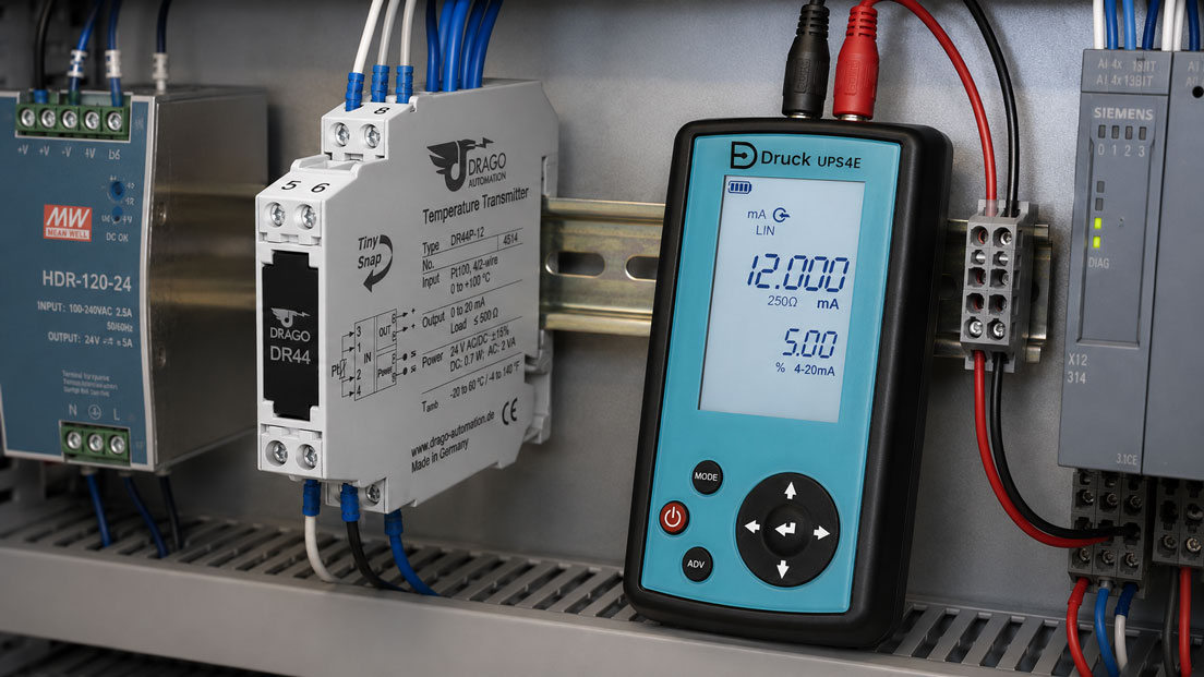
DIN-rail transmitters connect sensors, electrical measured variables and control systems. They convert, for example, a Pt100 signal, thermoelectric voltage, direct current or direct voltage into a standardised output signal such as 4–20 mA or 0–10 V.
At first glance, a transmitter inside a control cabinet appears to be a simple intermediate module: connect the input, apply 24 V DC and connect the output to the PLC. In practice, however, many errors are caused by an unsuitable device version, interchanged terminals, incorrect polarity, incompatible active and passive current signals or incorrect scaling.
It must also be clarified whether the transmitter is intended only to convert the signal or additionally provide galvanic isolation, power a field transmitter, duplicate a signal or monitor limits. Reliable signal transmission is achieved only when the input, output, auxiliary power and controller are considered as a complete measuring chain.
Table of Contents
- What is the purpose of a DIN-rail transmitter?
- Distinguishing transmitters, signal converters and isolating amplifiers
- Defining the input signal clearly
- Selecting an output signal suitable for the PLC
- Planning the 24 V DC power supply correctly
- Distinguishing 2-, 3- and 4-wire technology
- Assigning active and passive current signals correctly
- Reading the terminal diagram systematically
- Scaling the input and output correctly
- Checking the load resistance and available loop voltage
- When is galvanic isolation useful?
- Planning screening, earth and potential equalisation
- Connecting Pt100 and resistance sensors
- Connecting thermocouples and mV signals
- Distinguishing current and voltage inputs
- Signal duplication and multiple outputs
- Configuring the transmitter
- Commissioning step by step
- Testing a 4–20 mA measuring chain
- Typical wiring and selection errors
- Practical example: Preparing a Pt100 signal for a PLC
- Documentation inside the control cabinet
- Information required for device selection
- Which products are suitable?
- Conclusion
- Frequently asked questions
What is the purpose of a DIN-rail transmitter?
A transmitter receives an input signal, processes it and provides a defined output signal. The input signal can come directly from a sensor or from an upstream measuring instrument.
Typical inputs include:
- Pt100 and Pt1000,
- thermocouples,
- resistance and potentiometers,
- mV signals,
- 0–10 V or other DC voltages,
- 0–20 mA and 4–20 mA,
- alternating current and alternating voltage,
- frequency and pulse signals.
Typical outputs include:
- 4–20 mA,
- 0–20 mA,
- 0–10 V,
- 2–10 V,
- relay or transistor outputs,
- digital communication signals.
The transmitter can additionally perform one or more of the following tasks:
- scaling the measuring range,
- linearising a sensor signal,
- galvanic isolation,
- powering a 2-wire transmitter,
- filtering and damping,
- monitoring sensor breaks and short circuits,
- signal duplication,
- limit monitoring.
The description “transmitter for 4–20 mA” is therefore not sufficient for device selection. The input, output, power supply, isolation and required additional functions must be specified completely.
Distinguishing transmitters, signal converters and isolating amplifiers
These terms are frequently used interchangeably in everyday practice. However, their main functions differ.
| Device type | Main function | Example |
|---|---|---|
| Transmitter | Measures or processes a physical variable and generates a standard signal | Pt100 to 4–20 mA |
| Signal converter | Converts one electrical signal format into another | 0–10 V to 4–20 mA |
| Isolating amplifier | Transmits a signal with galvanic isolation | 4–20 mA to galvanically isolated 4–20 mA |
| Transmitter power supply | Powers a field transmitter and galvanically isolates its signal | 2-wire pressure transmitter connected to a PLC |
| Signal splitter | Generates several mutually isolated output signals | One 4–20 mA input to two 4–20 mA outputs |
| Limit switch | Compares the measured value with a limit | Relay switches above 15 mA |
A device can combine several of these functions. A universal transmitter can, for example, measure a Pt100 signal, linearise it, galvanically isolate it and output it as 4–20 mA.
Nevertheless, it should always be clarified before ordering which functions are actually included in the specific version. Not every transmitter automatically provides galvanic isolation or transmitter power.
Defining the input signal clearly
The input type determines how the transmitter must be wired and configured.
At least the following information is required before selection:
- signal type,
- lower and upper input value,
- active or passive source,
- DC or AC variable,
- sensor connection using 2-, 3- or 4-wire technology,
- unidirectional or bidirectional signal direction,
- required linearisation,
- possible fault or overrange range.
The designations alone are frequently insufficient. A “voltage” input may, for example, be designed for 0–10 V, ±10 V, 0–60 mV or several switchable ranges.
With a current input, it must also be clarified whether the upstream device supplies the current itself or requires an external loop power supply.
For temperature sensors, the sensor type, number of conductors and measuring range are decisive. A Pt100 and a thermocouple provide fundamentally different signals and must not be connected to the same input unless the device has been reconfigured accordingly.
Selecting an output signal suitable for the PLC
The transmitter output must be electrically and functionally compatible with the downstream input.
Typical combinations include:
- 4–20 mA output connected to a passive PLC current input,
- passive 4–20 mA output with an external loop power supply,
- 0–10 V output connected to a high-impedance voltage input,
- relay output connected to a digital PLC input,
- pulse output connected to a high-speed counter input.
A 4–20 mA output is frequently appropriate for:
- longer cable routes,
- industrial environments with electrical interference,
- decentralised control cabinets,
- existing current inputs,
- required detection of cable interruptions.
A 0–10 V output may be appropriate for:
- short cables inside a control cabinet,
- existing voltage inputs,
- a shared and stable reference potential,
- conventional building or machine automation.
The PLC must be configured for exactly the same signal type. A 4–20 mA output connected to a 0–10 V input does not provide a correctly usable measured value.
Planning the 24 V DC power supply correctly
Many DIN-rail transmitters are powered with 24 V DC. Depending on the device, however, the permissible range may extend considerably below or above 24 V. The specific device version is always decisive.
The following must be checked for the power supply:
- permissible voltage range,
- polarity,
- power consumption per module,
- total output of the power supply unit,
- inrush current of several modules,
- fusing and conductor cross-section,
- voltage drop in long supply chains,
- behaviour during undervoltage,
- required redundancy.
The power supply unit should not be operated permanently at its output limit. In addition to the transmitters, the PLC, relays, sensors, valves and other 24 V loads must also be considered.
Particularly when the power supply is looped from one module to another, the voltage at the end of the terminal row may be lower than directly at the power supply unit. The actual supply voltage should therefore be measured at the device terminals under operating conditions.
A shared 24 V supply does not automatically mean that all signals may use the same potential. Galvanically isolated inputs and outputs can remain electrically isolated despite sharing the same auxiliary power supply.
Distinguishing 2-, 3- and 4-wire technology
2-wire technology
With a 2-wire transmitter, the power supply and signal transmission use the same two conductors. The measuring current is typically between 4 and 20 mA.
The current loop may, for example, consist of:
24 V power supply → transmitter → analogue input → return conductor
The transmitter regulates its current according to the measured value. The supply voltage must be sufficient for the transmitter, analogue input and all cable resistances.
3-wire technology
With a 3-wire device, the power supply and signal partly use a common reference.
Typical connections are:
- +24 V,
- 0 V,
- signal output.
The reference potential of the sensor, transmitter and PLC must be connected correctly. Potential differences or incorrectly routed return conductors can cause measurement errors.
4-wire technology
A 4-wire device has a separate power supply and an independent signal output.
Typical connections include:
- two connections for the auxiliary power supply,
- two connections for the output signal.
The signal output may be active or passive and galvanically isolated or non-isolated. The number of conductors alone does not answer these questions completely.
Assigning active and passive current signals correctly
The terms active and passive are a particularly frequent cause of wiring errors in 4–20 mA loops.
Active current output
An active output supplies the measuring current itself. It is normally connected to a passive current input.
Passive current output
A passive output regulates the current but requires an external loop voltage. It is connected in series with a suitable power supply and a passive input.
Active current input
An active input can provide a supply voltage for a 2-wire transmitter. This function is frequently described as transmitter power or loop power.
Passive current input
A passive input measures the applied loop current but does not provide power for the field device.
| Source | Input | Assessment |
|---|---|---|
| Active current output | Passive current input | Typical suitable combination |
| Passive current output | Passive input with external power supply | Suitable when connected correctly in series |
| Passive 2-wire transmitter | Active powered input | Suitable when the voltage and load resistance are compatible |
| Active current output | Active current input | May result in two voltage sources operating against each other |
| Passive output | Passive input without power supply | No functioning current circuit |
As manufacturers sometimes use these terms differently, the terminal and connection diagram of the specific device must be checked.
Reading the terminal diagram systematically
Before connection, the terminal diagram should be divided into four functional areas:
- auxiliary power,
- input,
- output,
- optional communication or service connections.
A typical terminal assignment could, for example, be:
| Terminal | Function |
|---|---|
| 1 | +24 V DC power supply |
| 2 | 0 V power supply |
| 3 | Input + |
| 4 | Input − |
| 5 | Output + |
| 6 | Output − |
This assignment is only an example. The terminals on actual devices may be arranged completely differently.
The following should be checked before switching on:
- Do the device number and terminal diagram match?
- Is the ordered version designed for 24 V DC?
- Have the input and output been connected correctly?
- Is the polarity correct?
- Is the current circuit complete?
- Is the PLC input configured for the correct signal type?
- Are unused terminals free from wire bridges?
- Are the ferrules and conductor cross-sections suitable?
With universal devices, it should additionally be checked whether the connection terminals perform different functions depending on the configured input type.
Scaling the input and output correctly
The transmitter maps the input measuring range to the output measuring range.
Example:
- input: 0–10 V,
- output: 4–20 mA.
| Input | Output | Scaled value |
|---|---|---|
| 0 V | 4 mA | 0 % |
| 2.5 V | 8 mA | 25 % |
| 5 V | 12 mA | 50 % |
| 7.5 V | 16 mA | 75 % |
| 10 V | 20 mA | 100 % |
For a temperature transmitter, the scaling could be:
- Pt100 measuring range: −50 to +150 °C,
- output: 4–20 mA.
This means:
- −50 °C: 4 mA,
- +50 °C: 12 mA,
- +150 °C: 20 mA.
The PLC must use exactly the same physical measuring range. If the transmitter is configured for −50 to +150 °C but the PLC is scaled to 0 to 200 °C, the electrical signal is correct but the displayed temperature value is still incorrect.
Typical scaling errors include:
- confusing 4–20 mA with 0–20 mA,
- entering the wrong range start,
- inverting the input and output,
- confusing °C and °F,
- confusing unipolar and bipolar ranges,
- changing the range in the device without adapting the PLC,
- applying scaling twice in several software levels.
Checking the load resistance and available loop voltage
A current output requires sufficient voltage to drive the required current through all resistances connected in series.
The total load resistance may include:
- the PLC input resistance,
- cable resistance,
- isolating amplifiers,
- indicators or recording instruments,
- surge protection,
- test resistors.
The voltage required across an ohmic load is calculated as follows:
U = I × R
Example with a PLC input of 250 Ω:
20 mA × 250 Ω = 5 V
The transmitter also requires its own minimum operating voltage. The power supply must therefore be greater than the sum of all required voltage drops.
If the available voltage is too low, the fault frequently appears only in the upper part of the measuring range:
- 4 mA works,
- 12 mA still works,
- 20 mA cannot be reached,
- the output remains at 17 or 18 mA, for example.
Connecting several PLC inputs in series is therefore permissible only after the total load resistance and potential conditions have been checked.
When is galvanic isolation useful?
Galvanic isolation prevents a direct conductive connection between two electrical circuits. Internally, the signal is transmitted magnetically, optically or capacitively, for example.
It is particularly useful for:
- different earth potentials,
- long cables between parts of a building,
- earth loops,
- interference from frequency converters or motors,
- measurements at higher electrical potentials,
- protecting a PLC input card,
- isolating several signal outputs,
- preventing mutual interference.
Depending on the device, isolation may be provided between:
- input and output,
- power supply and input,
- power supply and output,
- all three areas.
Full 3-way isolation is not provided by every device version. The permissible test and working voltage of the isolation must also be suitable for the application.
Galvanic isolation does not replace proper earthing, screening or surge-protection planning. It is one part of the overall EMC and potential concept.
Planning screening, earth and potential equalisation
Analogue signal cables should be routed separately from power cables. Particularly critical cables include those connected to:
- motors,
- frequency converters,
- contactors and solenoid valves,
- heating systems,
- transformers,
- switched-mode power supplies.
Twisted and screened cables are often appropriate for sensitive sensor and mV signals.
A consistent system concept must be used for screening. Uncontrolled screen earthing at both ends can cause equalising currents where potential differences exist. Screening at one end only may, by contrast, be less effective at high frequencies.
The appropriate solution depends on factors including:
- signal type,
- cable length,
- frequency range of the interference,
- potential equalisation within the building,
- manufacturer specifications,
- EMC concept of the control cabinet.
The screen, signal earth and protective conductor must not be connected together arbitrarily. Their functions must be clearly distinguished in the circuit diagram.
Connecting Pt100 and resistance sensors
A Pt100 changes its electrical resistance depending on the temperature. The transmitter supplies the sensor with a small measuring current and calculates the temperature from the resistance.
2-wire connection
With a 2-wire connection, the resistance of the connection cables is included in the measurement. With long cables, this can cause a relevant temperature error.
3-wire connection
The 3-wire circuit largely compensates for cable resistance when the conductors involved have similar resistances. It is widely used in industrial applications.
4-wire connection
The 4-wire circuit provides the most accurate compensation for cable resistance and is frequently used where high accuracy is required.
| Connection type | Advantage | Points to consider |
|---|---|---|
| 2-wire | Lowest wiring requirement | Cable resistance affects the measured value |
| 3-wire | Good compensation for conventional industrial applications | Conductor resistances should be as similar as possible |
| 4-wire | Best cable-resistance compensation | Greater connection and cable requirements |
With universal temperature transmitters, the number of conductors must also be configured. A bridge required for a 2-wire connection must not be used without verification in a 3- or 4-wire circuit.
Connecting thermocouples and mV signals
Thermocouples generate a small temperature-dependent thermoelectric voltage. This is frequently within the millivolt range and is therefore susceptible to interference.
The following must be considered:
- correct thermocouple type,
- correct polarity,
- suitable extension or compensating cable,
- cold-junction compensation,
- no unsuitable transition metals,
- screening and cable routing,
- sensor-break monitoring.
A type K thermocouple must not be configured as type J. The two types provide different thermoelectric voltages and characteristic curves.
If the polarity is reversed, the displayed value frequently moves in the wrong direction or becomes implausibly low as the temperature rises.
As the signal voltage is very small, thermocouple cables should not be routed parallel to motor or contactor cables.
Distinguishing current and voltage inputs
An input for 0–10 V normally has a high input resistance. A 4–20 mA input, by contrast, operates with a defined measuring resistor or a corresponding current-measurement circuit.
If the two signal types are confused, the result may be implausible values or overloading of the output.
On universal inputs, selection is frequently made using:
- DIP switches,
- jumpers,
- buttons and a display,
- PC software,
- a programming adapter,
- NFC or another service interface.
A software change alone is not always sufficient. Some devices additionally require a different terminal assignment or switch position.
After every change, the following should be checked:
- Is the input wired appropriately?
- Is the measuring range correct?
- Is the output signal still assigned correctly?
- Has the PLC scaling been adapted?
Signal duplication and multiple outputs
A sensor signal often has to be transmitted simultaneously to several systems, for example:
- PLC,
- local display,
- data logger,
- protective or monitoring system,
- building management system.
A 4–20 mA signal must not be connected arbitrarily in parallel to several current inputs. The current distribution would not be defined.
Connecting several inputs in series may be possible in principle, but it increases:
- the total load resistance,
- the risk of potential problems,
- the dependency of the devices on one another,
- the diagnostic effort.
For several independent systems, a signal splitter with galvanically isolated outputs is frequently the better solution.
The following must be defined:
- number of outputs,
- active or passive outputs,
- galvanic isolation between the outputs,
- fault behaviour if one output fails,
- accuracy of each output channel.
Configuring the transmitter
Universal transmitters are frequently not supplied with a fixed measuring range and must be configured for the application.
Typical parameters include:
- input type,
- lower and upper measuring range,
- output signal,
- signal direction,
- filter time,
- sensor-break behaviour,
- output during overrange or underrange,
- number of conductors for resistance sensors,
- unit,
- zero-point or offset correction.
Strong filtering stabilises the output but delays rapid measured-value changes. It should therefore be adapted to the process dynamics.
Defined fault behaviour may, for example, specify:
- an output below the normal measuring range in the event of sensor breakage,
- an output above the normal measuring range in the event of overrange,
- holding the last valid value,
- outputting a fixed substitute value.
The transmitter’s fault behaviour and the PLC evaluation must be compatible. A fault current is ineffective if the controller interprets it as a normal process value.
Commissioning step by step
- Check the device version: Compare the order code, input, output and power supply with the design.
- Check while de-energised: Inspect the terminals, bridges, DIP switches and conductor assignment.
- Document the configuration: Record the input type, measuring range, output and fault behaviour.
- Switch on the power supply: Measure the voltage and polarity directly at the device.
- Check the status indication: Assess the operating, fault and communication indicators.
- Simulate the input: Inject a known input value or connect a suitable sensor resistance.
- Measure the output: Check the corresponding current or voltage value.
- Compare the PLC indication: Compare the electrical output signal with the displayed process value.
- Test several points: Check the range start, midpoint and full-scale value.
- Test the fault condition: Simulate a sensor break or input failure in a controlled manner.
- Save the settings: Update the configuration and circuit diagram.
For a better assessment, not only 0 and 100 % but at least three to five points should be tested. This makes it easier to distinguish scaling, linearity and connection errors.
Testing a 4–20 mA measuring chain
A 4–20 mA measuring chain should be divided into individual sections:
- sensor or signal source,
- transmitter input,
- signal conversion,
- transmitter output,
- wiring,
- PLC analogue input,
- scaling and indication.
A current-loop calibrator can inject defined values into the PLC input.
Typical test points are:
| Current value | Percentage value | Purpose of the test |
|---|---|---|
| 4 mA | 0 % | Range start and zero scaling |
| 8 mA | 25 % | Lower intermediate point |
| 12 mA | 50 % | Midpoint of the measuring range |
| 16 mA | 75 % | Upper intermediate point |
| 20 mA | 100 % | Full-scale value |
If the PLC displays the correct values for the simulated currents, the input card and scaling are fundamentally plausible. The actual transmitter output can then be checked.
The UPS4E current-loop calibrator can measure and generate mA signals and, where required, power a passive current loop with 24 V.
However, current simulation alone does not test the sensor or transmitter input. To assess the complete chain, the actual sensor signal or a suitable sensor simulation must also be applied.
Typical wiring and selection errors
The input and output are interchanged
The field signal is connected to the output terminals while the PLC is connected to the input. The measuring circuit does not function.
The polarity of the 24 V supply is incorrect
The module remains inoperative or, depending on its protective circuitry, is subjected to electrical stress.
An active output is connected to an active input
Two supply voltages operate against each other. The signal is implausible or the current circuit is overloaded.
A passive loop has no power supply
No current flows even though the transmitter and PLC are fundamentally functional.
4–20 mA and 0–20 mA are confused
The range start is displayed incorrectly in the PLC.
The transmitter is correct, but the PLC scaling is incorrect
The electrical signal is correct, but the displayed process value is still wrong.
The total load resistance is too high
The output cannot reach 20 mA, particularly at the upper end of the measuring range.
Galvanic isolation is assumed but not verified
Potential differences and earth loops remain present.
The Pt100 conductor configuration is incorrect
Cable resistance or a missing bridge causes a significant measurement deviation.
The thermocouple type or polarity is incorrect
The temperature indication is implausible or moves in the wrong direction.
The screen is connected without a consistent concept
Equalising currents or high-frequency interference affect the measuring signal.
Excessive filtering is selected
Rapid process changes reach the PLC with a significant delay.
The configuration is not documented
After replacement, the original measuring range cannot be reconstructed reliably.
Practical example: Preparing a Pt100 signal for a PLC
The temperature of a hydraulic tank in an existing machine is to be measured. A Pt100 in a 3-wire configuration is installed in the tank. However, the new PLC has only a 4–20 mA input.
The intended temperature range is 0 to 100 °C. A DIN-rail temperature transmitter is used with:
- Pt100 input in a 3-wire configuration,
- measuring range from 0 to 100 °C,
- 4–20 mA output,
- 24 V DC power supply,
- galvanic isolation between the sensor and output.
The wiring is divided into three areas:
- Pt100 conductors to the measuring input,
- 24 V auxiliary power to the transmitter,
- 4–20 mA output to the PLC.
During commissioning, the Pt100 is initially replaced by a suitable resistance simulator.
Three points are tested:
| Simulated temperature | Expected output | Expected PLC indication |
|---|---|---|
| 0 °C | 4 mA | 0 °C |
| 50 °C | 12 mA | 50 °C |
| 100 °C | 20 mA | 100 °C |
The transmitter output provides the expected current values. However, at 12 mA the PLC displays 60 °C instead of 50 °C.
The inspection shows that the PLC channel was scaled to −20 to +140 °C. After correcting it to 0 to 100 °C, the current value and temperature indication agree.
The actual Pt100 is then reconnected. The temperature is additionally compared using a suitable reference instrument.
The example shows that the sensor, transmitter and PLC should be tested separately. A correct 4–20 mA signal does not automatically prove that the scaling in the controller is correct.
Documentation inside the control cabinet
Complete documentation simplifies commissioning, maintenance and subsequent replacement.
The following should be recorded:
- manufacturer and type of transmitter,
- article or order number,
- supply voltage,
- input signal and measuring range,
- sensor type and number of conductors,
- output signal and scaling,
- active or passive signal type,
- terminal assignment,
- galvanic isolation,
- filter and fault parameters,
- PLC channel and PLC scaling,
- test points and actual measured values,
- date of commissioning.
The configuration file should be stored together with the circuit diagram, PLC program and device documentation.
Clear equipment identification inside the control cabinet is also advisable. This allows a service technician to assign the transmitter quickly to the associated sensor and PLC channel.
Information required for device selection
At least the following information is required when selecting a DIN-rail transmitter:
- measured variable or sensor type,
- exact input-signal range,
- 2-, 3- or 4-wire connection,
- active or passive input signal,
- required output signal,
- active or passive output,
- lower and upper scaling values,
- available auxiliary power,
- maximum load resistance,
- required galvanic isolation,
- number of output channels,
- required accuracy,
- required response time,
- fault behaviour in the event of sensor breakage,
- ambient temperature,
- available space on the DIN rail,
- required approvals,
- configuration via switches, software or interface,
- documentation and calibration requirements.
A meaningful enquiry could read as follows:
DIN-rail temperature transmitter for a Pt100 in a 3-wire configuration, measuring range −50 to +150 °C, active 4–20 mA output, 24 V DC power supply, galvanic 3-way isolation, sensor-break output above 20 mA, accuracy of no more than 0.2 % of span and mounting on a 35 mm DIN rail.
Which products are suitable?
Transmitters
The transmitters category includes various devices for measuring, converting and conditioning electrical and sensor input signals.
The range is divided into application areas including:
- AC current transmitters,
- AC voltage transmitters,
- DC current transmitters,
- DC voltage transmitters,
- power transmitters,
- DIN-rail temperature transmitters,
- temperature head transmitters,
- universal transmitters.
Depending on the version, fixed or configurable measuring ranges, different auxiliary power supplies, galvanic isolation and standardised output signals are available.
DIN-rail temperature transmitters
DIN-rail temperature transmitters convert signals from Pt100, Pt1000 or thermocouple sensors, for example, into a standardised output signal.
Depending on the device, available features may include:
- universal sensor inputs,
- 2-, 3- and 4-wire connections,
- sensor-break and short-circuit detection,
- 4–20 mA or 0–10 V output,
- galvanic isolation,
- freely configurable measuring ranges,
- linearisation of different sensor types.
Measuring instruments for control-panel construction
In addition to transmitters, the measuring instruments for control-panel construction category also includes signal converters, isolating amplifiers, digital and analogue panel meters, current transformers, energy meters and Modbus I/O components.
This allows transmitters to be combined appropriately with displays, PLC interfaces, current transformers or other control-cabinet components.
UPS4E current-loop calibrator
The UPS4E current-loop calibrator supports the commissioning and troubleshooting of transmitters using current signals.
It provides functions including:
- measurement of mA signals,
- generation and simulation of defined current values,
- testing active and passive current loops,
- integrated 24 V loop power supply,
- step and ramp tests,
- voltage measurement,
- testing PLC analogue inputs,
- documentation of measured values.
This allows the transmitter output, wiring, PLC input and scaling to be isolated from one another and tested systematically.
Conclusion: Always consider the input, output and power supply as a complete measuring chain
A DIN-rail transmitter operates reliably only when the input signal, output signal, auxiliary power and downstream input are electrically compatible.
Distinguishing between active and passive 4–20 mA signals is particularly important. A passive output requires a loop voltage, while an active output supplies the measuring current itself.
With 24 V DC supplies, the polarity, permissible voltage range, power reserve and voltage drop must be taken into account. An existing 24 V supply rail is not automatically sufficient for every module.
Galvanic isolation can prevent potential differences and earth loops. However, it must be verified for the specific device version and does not replace a complete earthing, screening and EMC concept.
The scaling must be configured identically in the transmitter and PLC. Otherwise, an electrically correct 4–20 mA signal may still produce an incorrect process value.
During commissioning, several defined input and output points should be tested. Testing the sensor, transmitter, wiring and PLC separately allows faults to be located more quickly.
Frequently asked questions about DIN-rail transmitters
What is a DIN-rail transmitter used for?
It converts a sensor or measuring signal into a standardised output signal that can be processed by a PLC, display or control system.
Does every transmitter require 24 V DC?
No. 24 V DC is widely used, but other DC or AC voltages are possible depending on the device. The permissible range must be checked for the specific version.
What is the difference between an active and passive 4–20 mA output?
An active output supplies the loop current itself. A passive output requires an external loop voltage.
Why does the PLC display an incorrect value despite the correct output current?
The PLC is frequently scaled to a different measuring range or configured for 0–20 mA instead of 4–20 mA.
When is galvanic isolation required?
It is particularly useful where potential differences, earth loops, long cables or interference-prone areas exist, or where the field and control levels must be electrically isolated.
Can a 4–20 mA output be connected in parallel to two PLC inputs?
Arbitrary parallel connection is not permissible. A suitable signal splitter should be used for several independent outputs.
Why does the transmitter not reach 20 mA?
Possible causes include excessive total load resistance, insufficient supply voltage, incorrect scaling or a limitation of the input signal.
How is a DIN-rail transmitter tested?
Defined input values are applied and the corresponding output values are measured. It is also checked whether the PLC scales the output correctly.
Can the UPS4E simulate a Pt100 input?
No. The UPS4E is designed for current loops and electrical process signals. A suitable temperature simulator is required for Pt100, thermocouple or resistance signals.
Which information does ICS Schneider require for selection?
The required information includes the input signal, measuring range, sensor connection, output signal, active or passive signal type, power supply, load resistance, galvanic isolation, accuracy, response time, DIN-rail space and required configuration method.