


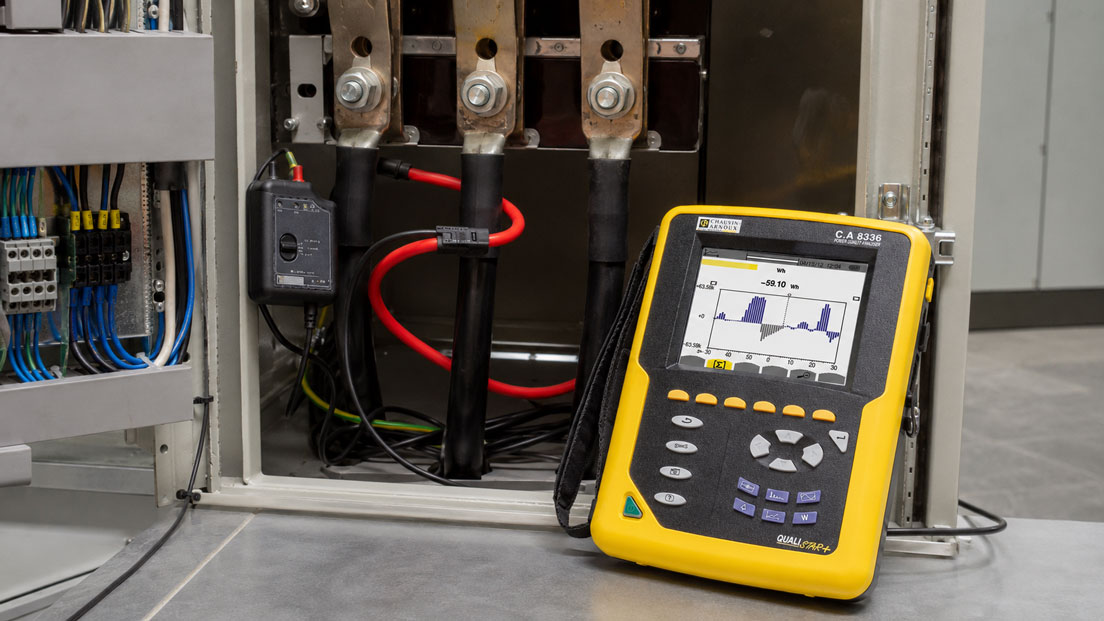
In industrial control cabinets, main distribution boards and energy systems, currents often have to be measured on large cables or solid busbars. Conventional current clamps quickly reach their mechanical limits: the clamp head cannot be opened far enough, the busbar is too wide or there is insufficient space between the conductors.
Flexible current sensors solve this problem with a bendable measuring loop. It can be placed around large conductors, busbars or parallel cables and then closed. Many of these sensors operate according to the Rogowski principle and are particularly suitable for high alternating currents, temporary load measurements, energy analyses and retrofit applications.
However, the flexible design alone does not guarantee a correct measurement. The measuring range, frequency bandwidth, output signal, position of the coil, current direction, neighbouring conductors and connected measuring instrument all influence the result. It is also particularly important to distinguish between AC, DC and power measurements.
Table of Contents
- How does a Rogowski coil work?
- When is a flexible current sensor useful?
- Flexible coil or conventional current clamp?
- Why Rogowski coils cannot measure direct current
- Selecting the measuring range and minimum current correctly
- Which conductors may be enclosed together?
- Positioning the coil and conductor correctly
- Influence of neighbouring conductors and busbars
- Understanding the integrator and output signal
- Considering TRMS, frequency and current waveform
- Measuring power and energy with Rogowski coils
- Investigating dynamic currents with an oscilloscope
- Installation in a confined control cabinet
- Measurement category and occupational safety
- Typical measurement errors
- Practical example on a main distribution board
- Selecting the correct flexible current sensor
- Which measuring instruments and products are suitable?
- Conclusion
- Frequently asked questions
How does a Rogowski coil work?
A Rogowski coil consists of a uniformly wound conductor loop without a ferromagnetic core. When it is placed around a current-carrying conductor, it detects the conductor’s changing magnetic field.
The coil initially generates a voltage proportional to the rate of change of the current:
ucoil(t) ∝ di(t) / dt
To obtain a measured value proportional to the actual current, this signal is electronically integrated:
i(t) ∝ ∫ ucoil(t) dt
Depending on the sensor design, this integrator circuit is located in the connected measuring instrument, in a separate electronics housing or directly in the display unit.
Because there is no iron core, conventional magnetic core saturation does not occur. This facilitates the measurement of high currents and large current peaks. Nevertheless, the actual permissible range is limited by the coil, integrator, output signal and connected measuring instrument.
When is a flexible current sensor useful?
Flexible current sensors are particularly helpful when a rigid clamp head cannot mechanically fit around the conductor or cannot be fully closed once installed.
Typical applications include:
- large cable cross-sections and cable bundles,
- rectangular or wide busbars,
- compact control cabinets,
- main distribution boards carrying several hundred or several thousand amperes,
- temporary energy and load-profile measurements,
- retrofitting existing systems without disconnecting the conductor,
- measurements on transformers, generators and large motors,
- analysis of inrush currents and dynamic load profiles.
The loop can often be routed through a narrow gap and then closed around the conductor. This means that neither a solid busbar has to be dismantled nor a power cable routed through a closed current transformer.
Flexible coil or conventional current clamp?
| Criterion | Flexible Rogowski coil | Conventional current clamp |
|---|---|---|
| Mechanical enclosure | Highly flexible for large or irregularly shaped conductors | Limited by the opening and shape of the clamp head |
| High alternating currents | Depending on the model, up to the kA range | Model-dependent, often with a lower maximum range |
| Direct-current measurement | Not possible using the Rogowski principle | Possible with a Hall-effect clamp |
| Low currents | Often more limited, depending on the model | Suitable clamps may provide greater sensitivity |
| Magnetic saturation | No ferromagnetic core | Must generally be considered with current-transformer-based clamps |
| Evaluation electronics | Integrator or compatible display required | Usually fully integrated in handheld instruments |
| Installation position | Closure, conductor position and neighbouring magnetic fields must be considered | Clamp jaws must close cleanly and completely |
For high alternating currents on large busbars, the flexible coil is often the more practical solution. For low direct currents, battery systems or measurements requiring high DC accuracy, a suitable Hall-effect measuring instrument is required instead.
Why Rogowski coils cannot measure direct current
The Rogowski coil responds to a change in current. With constant direct current, the magnetic field remains unchanged after the transient process. The coil then generates no continuously usable signal.
Rogowski sensors are therefore suitable for:
- sinusoidal alternating currents,
- distorted alternating currents,
- harmonics within the specified bandwidth,
- inrush and load-current profiles,
- pulsating or time-varying current components.
A constant DC component is not detected. For example, if 200 A of direct current flows with superimposed ripple, a Rogowski coil displays only the time-varying component within its bandwidth.
For photovoltaic systems, battery storage systems, DC links or electric-vehicle technology, it must therefore be established whether pure direct current, alternating current or both need to be measured.
Selecting the measuring range and minimum current correctly
Flexible current sensors are often available with very large maximum ranges. However, a 10 kA sensor is not automatically the best choice for a system that normally draws only 20 A.
An excessively large range can have the following disadvantages:
- lower resolution at small currents,
- greater relative measurement error in the lower part of the range,
- base-load changes are more difficult to detect,
- greater susceptibility to interference signals.
For switchable sensors, the smallest range that safely covers the expected operating current and possible peaks should therefore be selected.
At least three values are required for selection:
- the smallest current that must still be detected reliably,
- the normal operating current,
- the highest RMS and peak current.
The maximum current specification must also not be confused with the maximum measurable current peak. With highly distorted signals, the permissible crest factor or peak range of the complete measuring chain must be considered.
Which conductors may be enclosed together?
To measure the current of an individual phase, only the corresponding conductor should generally be enclosed.
If the outgoing and return conductors are enclosed together by the loop, their magnetic fields act in opposite directions. The resulting indication may therefore be almost zero even though a high current is flowing in both conductors.
In a three-phase system:
- enclose only L1 to measure the current in L1,
- enclose only L2 to measure the current in L2,
- enclose only L3 to measure the current in L3,
- for power measurement, assign each current channel to the correct voltage.
Several parallel conductors belonging to the same phase may be enclosed together if the total current of that phase is to be measured and all currents flow in the same direction.
If all line conductors are enclosed together, the sensor does not measure the sum of their magnitudes but the vector sum of the currents. In a balanced system, this is approximately zero. Such an arrangement is used for differential or leakage-current measurement and requires a sensor and measuring range suitable for that purpose.
Positioning the coil and conductor correctly
An ideal Rogowski coil would be largely independent of the exact conductor position. Real sensors, however, have design-related position influences, particularly near the closure or return section.
For the most reliable measurement possible:
- the loop should be completely closed,
- the conductor should not lie directly against the closure,
- the coil should not be twisted or kinked,
- the permissible minimum bending radius should be observed,
- the conductor should be positioned favourably within the loop wherever possible,
- the current direction specified by the manufacturer should be observed.
The direction marking is often less critical for a simple magnitude measurement. For power, phase or energy analyses, however, it determines the correct sign and phase relationship.
Influence of neighbouring conductors and busbars
In a compact distribution board, the measuring loop is often located directly next to other conductors carrying high currents. Their magnetic fields can influence the result.
Particularly problematic conditions include:
- the loop closure being located directly next to a neighbouring busbar,
- several high-current conductors positioned close together,
- unintentionally enclosing part of a second conductor,
- strongly unbalanced currents,
- poorly routed sensor cables.
The loop should be routed completely around the required conductor and should be kept as far away as possible from neighbouring high-current sources. If this is mechanically impossible, the additional positional uncertainty must be considered when assessing the result.
For comparative measurements, all three phases should be measured with the loops arranged as similarly as possible. Different loop positions may otherwise produce apparent phase differences that do not originate from the system itself.
Understanding the integrator and output signal
A bare Rogowski coil does not provide a directly readable current value. The integrator first converts the coil signal into an output signal proportional to the current.
Depending on the design, the following may be available:
- integrated digital indication in amperes,
- AC voltage output for multimeters and recorders,
- BNC output for oscilloscopes and power analysers,
- a fixed conversion ratio such as mV/A,
- switchable sensitivities for different current ranges.
With an output of 1 mV/A, for example, 500 A corresponds to an output signal of 500 mV. The connected instrument must be capable of processing this voltage range, frequency and waveform correctly.
The following must therefore be checked before measurement:
- output unit and sensitivity,
- selected range of the current sensor,
- input range of the multimeter or recorder,
- input impedance and connection type,
- battery or supply voltage of the evaluation electronics.
An incorrect range setting can produce a measurement error by a factor of 10, 100 or 1,000.
Considering TRMS, frequency and current waveform
Many industrial loads do not draw an ideal sinusoidal current. Variable-frequency drives, switched-mode power supplies, welding equipment and controlled heating systems produce distorted current waveforms.
A True RMS measuring system is therefore required to determine the correct RMS value. However, the TRMS designation alone is not sufficient: the frequency bandwidth of both the current sensor and connected measuring instrument must cover the relevant signal components.
| Measuring task | Important requirement |
|---|---|
| Mains current at 50 or 60 Hz | Suitable RMS range and sufficient basic accuracy |
| Harmonic analysis | Sufficient bandwidth and low phase error |
| Variable-frequency drive output | The measuring instrument and sensor must be suitable for the switching frequency and current waveform |
| Inrush current | Peak, inrush or fast recording function |
| Oscilloscope measurement | Known bandwidth, sensitivity and maximum current peak |
A sensor optimised for energy recording at mains frequency is not automatically suitable for fast switching transients. Conversely, a wide-bandwidth oscilloscope probe may be unnecessarily complex for a simple long-term measurement.
Measuring power and energy with Rogowski coils
Current alone is not sufficient for a power measurement. Voltage and current must be recorded simultaneously and combined with the correct phase relationship.
For three-phase measurements:
- current sensor L1 must be assigned to voltage L1,
- current sensor L2 must be assigned to voltage L2,
- current sensor L3 must be assigned to voltage L3,
- all current sensors must be installed in the same defined direction.
An interchanged phase or reversed loop direction can result in negative power, an incorrect power factor or partial cancellation of the total power.
The phase displacement of the current sensor is also relevant for precise power and energy analyses. Particularly at a low power factor, even a small additional phase error can cause a noticeable power measurement error.
For longer measuring campaigns, battery life, secure mounting, storage duration and the power supply of the evaluation electronics must also be considered.
Investigating dynamic currents with an oscilloscope
To display rapid current profiles, a flexible current probe with a suitable bandwidth is connected to an oscilloscope.
Typical applications include:
- welding-current pulses,
- switching operations in power electronics,
- motor starting and commutation,
- current profiles on converters,
- power-supply and inverter diagnostics,
- short overload and inrush events.
The conversion ratio and, where applicable, the probe factor must be configured correctly on the oscilloscope. Offset, bandwidth limitation, sampling rate and maximum input voltage must also be considered.
Because a Rogowski coil cannot detect a DC component, the displayed waveform must not be interpreted as the complete AC/DC current without further assessment.
Installation in a confined control cabinet
Before installation, it should be checked whether the loop length, loop diameter and closure mechanism suit the available space.
A very long loop makes it easier to enclose large busbars but requires more space for routing. A short mini loop can be routed more easily between closely spaced conductors but may not completely enclose large cable bundles.
The electronics unit and measuring leads should be secured so that:
- no tensile force acts on the loop closure,
- no cables enter moving or hot areas,
- the control-cabinet door can be closed,
- controls and displays remain accessible,
- the sensors cannot move during a long-term recording.
Magnetic holders may only be used at suitable locations and must not interfere with conductive components or ventilation openings.
Measurement category and occupational safety
The flexible design makes installation easier, but it does not automatically make measurement on exposed live busbars safe.
The complete measuring chain must be suitable for the measuring location. This includes:
- measuring loop,
- insulation and closure,
- connecting leads,
- evaluation electronics,
- multimeter, recorder or oscilloscope,
- adapters and accessories.
The measurement category and rated voltage must suit the system. A specification such as CAT III or CAT IV applies only under the conditions stated in the data sheet.
Installation and connection may only be carried out by qualified personnel in accordance with the company’s safety procedures. Wherever possible, the circuit should be isolated before installation. Work near exposed live parts requires suitable protective measures and personal protective equipment.
Typical measurement errors
Outgoing and return conductors are enclosed together
The magnetic fields largely cancel each other out. The displayed current is too low or almost zero.
All three phases are enclosed by one loop
The resulting vector sum of the currents is measured, not the sum of the individual phase currents.
The Rogowski coil is used for direct current
A constant DC current is not detected. At most, a superimposed AC component is displayed.
The loop is not completely closed
The magnetic sensing path is not configured as intended. The measured value may deviate significantly.
The conductor lies directly against the closure
The design-related positional error may increase.
The measuring range is unnecessarily high
Small operating and base-load currents are resolved less effectively.
The output ratio is configured incorrectly
The indication deviates from the actual current by a constant factor.
The current direction is reversed during a power measurement
Power and power factor are calculated with the wrong sign or phase relationship.
The connected multimeter does not have sufficient bandwidth
Distorted currents and higher-frequency components are recorded incompletely.
Neighbouring high-current conductors influence the loop
The measurement contains an additional component caused by the external magnetic field.
Practical example: Load measurement on an industrial main distribution board
A production facility needs to determine why the current loading of a main distribution board rises sharply at certain times. The three phases consist of wide copper busbars with only a small spacing between them. A conventional current clamp cannot be closed around the busbars.
Three identical flexible current sensors are used. Each measuring loop is routed around one individual phase and installed in accordance with the specified current direction.
Before recording begins, the following are checked:
- correct assignment of L1, L2 and L3,
- complete loop closure,
- identical positioning of the three measuring loops,
- correct current range,
- plausible current and power values,
- sufficient battery life and storage duration.
During normal operation, the measurement shows currents between 350 and 500 A. At the beginning of the shift, the current on two phases rises well above 800 A for several minutes.
Comparison with the operating log reveals that several large motors and an electric heater are switched on simultaneously. The load distribution between the phases is also not completely balanced.
After introducing staggered switching and adjusting individual loads, the measurement is repeated. The maximum current loading decreases and the phase currents become more balanced.
Without the flexible current sensors, the main distribution board would have required extensive modification for a stationary measurement or additional permanently installed current transformers.
Selecting the correct flexible current sensor
At least the following information is required for selection:
- alternating current or direct current,
- minimum, normal and maximum current,
- expected peak or inrush current,
- mains frequency and relevant harmonics,
- conductor diameter or busbar dimensions,
- available space between the conductors,
- single-phase or three-phase measurement,
- current, power or energy analysis,
- direct display, voltage output or BNC output,
- multimeter, recorder, power analyser or oscilloscope as the evaluation instrument,
- required bandwidth and recording duration,
- measurement category and rated voltage,
- indoor, outdoor or industrial field use,
- accuracy and calibration requirements.
A meaningful enquiry could read as follows:
Three-phase AC measurement on three copper busbars, normally 300 to 800 A, briefly up to a maximum of 1,500 A, mains frequency 50 Hz with harmonic analysis, available spacing 18 mm, loop circumference at least 600 mm and connection to a power analyser.
Which measuring instruments and products are suitable?
Flexible current sensors
The flexible current sensors category includes Rogowski measuring loops with different current ranges, loop lengths, outputs and bandwidths.
The parent category current clamps / flexible current sensors additionally includes conventional AC/DC current clamps, leakage-current clamps and power clamps.
AmpFLEX A100 up to 10 kA
The AmpFLEX A100 is designed for AC measurements from 0.5 A to 10 kA.
Depending on the version, one or two measuring ranges and loop lengths of 45 cm, 80 cm or 1.20 m are available. The AC voltage signal can be connected to suitable multimeters, wattmeters and other evaluation instruments.
The A100 is particularly suitable for large conductors, busbars and high industrial alternating currents.
A130 AmpFlex for three-phase measurements
The A130 AmpFlex consists of three flexible current-measuring loops for three-phase applications.
The measuring range extends up to 3 kA. The version is suitable for power, energy and harmonic measurements, among other applications, where all three phases are to be measured using identical sensors.
Each of the three current channels must be assigned to the correct phase voltage in the measuring instrument.
DigiFLEX MA400D and MA4000D with direct display
The DigiFLEX MA400D and MA4000D combine a flexible measuring loop with an integrated digital display.
The MA400D is suitable for currents up to 400 A, while the MA4000D is intended for industrial systems up to 4,000 A. The instruments display the TRMS alternating current directly and provide hold and maximum-value functions.
They are particularly practical for mobile servicing applications where no additional multimeter or evaluation instrument is to be connected.
F3000 with flexible measuring head
The F3000 is a compact TRMS current clamp with a flexible measuring head and integrated display.
It measures alternating currents up to 3,000 A and, with a maximum enclosure diameter of 110 mm, is suitable for large cables and difficult-to-access measuring points.
Its direct display makes it a practical solution for maintenance, commissioning and rapid load-current checks.
MiniFLEX MA200 for oscilloscopes
The MiniFLEX MA200 is designed for dynamic AC measurements using an oscilloscope.
It covers currents from 0.5 A to 3,000 A and provides a bandwidth of up to 1 MHz. Different loop sizes enable use at small measuring points as well as on larger conductors.
The MA200 is particularly suitable for transients, welding currents, power electronics and rapidly changing current profiles.
Conclusion: Flexible current sensors solve mechanical measurement problems but require careful system design
Flexible current sensors are an effective solution for high alternating currents, large conductor cross-sections and confined control cabinets. The flexible Rogowski coil can be placed around cables and busbars that cannot be accessed using a conventional current clamp.
The Rogowski principle does not use a ferromagnetic core and is therefore suitable for high currents and wide frequency ranges. However, it cannot detect constant direct current.
For a correct measurement, the loop must be completely closed, placed around the correct conductor and selected to suit the current range. Outgoing and return conductors or several different phases must not be enclosed together for a normal phase-current measurement.
For power and energy analyses, the current direction, phase assignment, phase displacement and bandwidth are also decisive. A current probe with a correspondingly wide bandwidth and an oscilloscope are required for dynamic current profiles.
Selection should therefore not be based solely on the maximum current. The loop size, minimum measurable current, output signal, integrator, frequency range, measurement category and connected evaluation instrument together form the complete measuring chain.
Frequently asked questions about flexible current sensors and Rogowski coils
What is a Rogowski coil?
A Rogowski coil is a flexible, air-cored current sensor without a ferromagnetic core. It detects the changing magnetic field of an AC conductor. An integrator circuit converts the coil signal into a proportional current value.
Can a Rogowski coil measure direct current?
No. A constant direct current does not generate a continuously changing magnetic field and is therefore not detected. A Hall-effect current clamp, for example, is required for DC measurements.
Why does the sensor display almost zero amperes?
The outgoing and return conductors may have been enclosed together. Their magnetic fields largely cancel each other out. An incompletely closed loop or incorrect range setting may also be the cause.
May I enclose several conductors with one coil?
Several parallel conductors belonging to the same phase may be enclosed together if their total current is to be measured and all currents flow in the same direction. Different phases or outgoing and return conductors must not be enclosed together for a normal load-current measurement.
Must the conductor be positioned exactly in the centre of the loop?
A central position or one away from the closure is generally advantageous. However, the permissible positional deviation depends on the design of the specific sensor. The manufacturer’s specifications are decisive.
Can I connect a flexible current sensor directly to a multimeter?
Only if the current sensor has suitable integrator electronics and an output compatible with the multimeter. Sensitivity, voltage range, frequency bandwidth and TRMS suitability must be compatible.
Which loop length do I need?
The loop must fully enclose the conductor or busbar with sufficient additional length. At the same time, it should not be unnecessarily long because surplus loop length must be routed safely inside the confined control cabinet.
Is a Rogowski coil suitable for power measurement?
Yes, provided that the sensor has a sufficiently low and known phase error and is evaluated together with the correct phase voltage. The current direction and phase assignment must be correct.
Which information does ICS Schneider require for selection?
The required information includes the current type, minimum and maximum current, peak current, frequency range, conductor or busbar dimensions, available installation space, number of phases, required output signal, existing evaluation instrument, measurement category and requirements for accuracy and recording.