


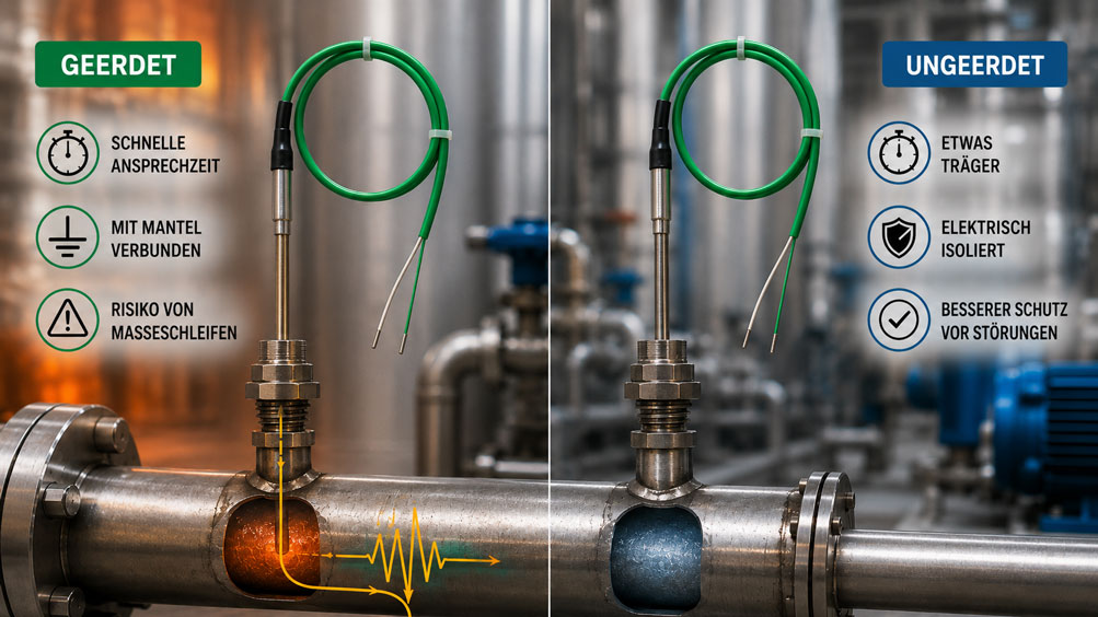
A Type K thermocouple is installed directly in a metallic machine component and is intended to detect rapid temperature changes. With a grounded measuring junction, the sensor responds quickly and reliably. However, after connection to a PLC, the measured value begins to fluctuate or shifts depending on which other devices on the machine are switched on. If the same setup is used with an ungrounded measuring junction, the interference disappears – but the temperature indication responds somewhat more slowly.
The reason lies in the internal design of the thermocouple. With a grounded junction, the actual connection point of the two thermocouple wires is electrically connected to the metallic sensor sheath. This allows heat to reach the measuring junction very directly. At the same time, however, there is an electrical connection between the thermocouple and the process or machine ground. With an ungrounded version, the measuring junction is electrically isolated inside the sheath. This improves electrical decoupling, but the additional thermal transition can increase the response time.
Which version is more suitable therefore depends not only on the required temperature accuracy. Process dynamics, sensor diameter, installation, heat transfer, potential differences, the EMC environment, input circuitry and galvanic isolation of the signal conditioning all influence the overall result. A grounded thermocouple can work perfectly in a well-designed measurement chain, while the same design may cause significant interference in a complex grounded machine.
The decision between a grounded and an ungrounded measuring junction is therefore always a compromise between the most direct possible heat transfer and the best possible electrical decoupling. What matters is not only the sensor itself, but the complete measurement chain from the process to the evaluation device.
How does the measuring junction of a thermocouple work?
A thermocouple consists of two conductors made from different metal alloys. When they are connected at the measuring junction, a temperature-dependent thermoelectric voltage is generated. To determine the temperature, this very small voltage is evaluated together with the temperature of the reference junction or cold junction.
In industrial mineral-insulated thermocouples, the thermocouple wires are often located inside a metallic sheath and are separated from each other and from the sheath by compacted mineral insulation material. At the actual measuring tip, however, the two thermocouple wires must be connected to each other. This is precisely where the different “grounded” and “ungrounded” designs arise.
The difference therefore does not concern the thermocouple type itself. A Type K thermocouple can be manufactured with either a grounded or an ungrounded measuring junction. The material pairing, characteristic curve and fundamental thermocouple principle remain the same. What changes primarily is the thermal contact with the sheath and the electrical connection to the process.
What is a grounded thermocouple?
With a grounded measuring junction – commonly referred to as a grounded junction – the connection between the two thermocouple wires is welded to the metallic base or sheath of the sensor tip. The measuring junction and the sensor sheath are therefore electrically at the same potential.
From a thermal perspective, this design is advantageous because the heat path between the sensor sheath and the measuring junction is very short. Temperature changes at the sheath can therefore be transferred quickly to the thermocouple. Particularly with small sheath diameters and good heat transfer, very fast measurements can be achieved.
Electrically, however, a connection to the process is created at the same time. If the metallic sheath is screwed into a grounded machine housing, for example, the thermocouple measuring junction is also at this potential. If the signal side is grounded at another point as well, an additional current path can be created.
What is an ungrounded thermocouple?
With an ungrounded measuring junction, the welded thermocouple wires are electrically isolated from the metallic sheath. The insulating material of the mineral-insulated cable remains between the measuring junction and the outer sheath. As a result, the thermocouple offers significantly better electrical isolation from the process.
This advantage is particularly noticeable in systems with potential differences, frequency converters, motors, heaters, multiple grounding points or sensitive measuring amplifiers. Process-side interference voltages cannot enter the thermocouple circuit as directly through the sensor sheath.
However, the additional insulation path also creates additional thermal resistance. The measuring junction therefore often follows the temperature of the outer sheath somewhat more slowly. The actual magnitude of this difference depends strongly on the specific sensor design.
Grounded and ungrounded compared directly
| Criterion | Grounded measuring junction | Ungrounded measuring junction |
|---|---|---|
| Electrical connection to sheath | Yes | No |
| Heat transfer to measuring junction | Very direct | Via an additional insulation layer |
| Response time | Often faster | Often somewhat slower |
| Electrical decoupling from the process | Low | Significantly better |
| Risk of ground loops | Higher | Lower |
| Typical application | Rapid temperature changes in electrically non-critical installations | EMC-critical systems and measuring points with possible potential differences |
The table describes the general tendency, but it does not replace an assessment of the specific sensor. A thin ungrounded mineral-insulated thermocouple, for example, may respond faster than a significantly more massive grounded sensor. For the actual response time, sensor diameter, sheath material, design and installation conditions are therefore at least equally important.
Why does a grounded junction often respond faster?
Temperature is not measured immediately as soon as the process temperature changes. Heat must first travel from the medium or component to the actual measuring junction of the thermocouple. Every thermal transition requires time.
With a grounded junction, the thermocouple is in direct thermal contact with the sensor tip. In an ungrounded design, additional electrically insulating material lies between the metallic sheath and the measuring junction. This can slightly dampen the heat flow.
How quickly a thermocouple responds in practice is determined by several factors:
- Sheath diameter: Small diameters have less thermal mass and generally respond faster.
- Installation and immersion depth: A measuring tip that is not immersed sufficiently can be influenced more strongly by ambient temperature or heat conduction.
- Medium and flow: Flowing liquids and gases transfer heat differently from stationary media or solid components.
- Thermowell: An additional thermowell increases thermal mass and can significantly increase response time.
- Contact with the measuring surface: In surface and machine measurements, the quality of the mechanical contact has a major influence on heat transfer.
A grounded measuring junction should therefore not be selected solely on the basis that it is “faster”. If the sensor is subsequently installed inside a massive thermowell, the difference between grounded and ungrounded junctions may become practically insignificant compared with the influence of the thermowell itself.
How do ground loops occur with thermocouples?
Thermocouples generate only very small electrical signals. Even relatively small interference voltages can therefore have a visible effect on the temperature indication. Unintended electrical connections between the measuring junction, machine, control cabinet and evaluation device are particularly problematic.
A typical case occurs when a grounded thermocouple is screwed into a metallic machine housing. The grounded measuring junction creates an electrical connection between the thermocouple and machine ground. If the input of the measuring device or PLC is also connected to ground at another point, a closed current path can form.
If equalizing or interference currents flow through this path, they are superimposed on the actual thermocouple signal. As a result, the measured value may jump, drift slowly or change as soon as motors, heaters, frequency converters or other electrical loads are switched on. Such symptoms are often incorrectly interpreted as a defective temperature sensor.
What role does galvanic isolation play?
A grounded measuring junction does not necessarily result in an incorrect measurement. The decisive factor is how the input of the downstream temperature transmitter or measuring device is designed. A galvanically isolated input can prevent a problematic ground loop from closing through the signal path.
| Measurement chain | Assessment | Typical consequence |
|---|---|---|
| Grounded thermocouple + non-isolated input + different ground potentials | Critical | Ground loops and interference possible |
| Grounded thermocouple + galvanically isolated transmitter | Significantly more favorable | Fast measuring junction can operate with low interference despite process contact |
| Ungrounded thermocouple + suitable input | Very good electrical decoupling | Lower risk of process-side interference |
| Ungrounded thermocouple + incorrect shielding or cable routing | Interference still possible | Junction isolation alone does not solve every EMC problem |
This makes it clear why the selection must not end with the sensor itself. An ungrounded thermocouple is not a substitute for a properly designed signal path, and a grounded thermocouple is not automatically unsuitable for industrial systems. The electrical architecture of the entire measurement chain is decisive.
Why installation is often more important than junction type
In many applications, significantly larger temperature errors are caused by the installation than by the choice between a grounded and ungrounded measuring junction. A sensor that is too short, poor thermal coupling, strong heat conduction through the stem or an unfavorable position within a pipe can influence the measured value much more strongly.
Especially in pipelines, the measuring tip should extend sufficiently into the relevant temperature zone. For measurements on machine surfaces, reproducible contact with the component must be ensured. If a thermowell is additionally installed between the medium and the thermocouple, its material, wall thickness and geometry determine a large part of the dynamic behavior.
The cable between the sensor and the evaluation device is also part of the measurement chain. Thermocouples must not simply be extended with ordinary copper cables. Suitable thermocouple or extension cables, correct polarity and proper cold-junction compensation are required so that the electrical isolation of the sensor is not compromised by errors elsewhere in the system.
Systematically diagnosing unstable temperature measurements
If a thermocouple measurement fluctuates or the measured value changes depending on the operating state of the machine, it should first be clarified whether the problem is thermal or electrical. A particularly strong indication of an electrical cause is a measured value that changes when motors, frequency converters, heaters or other high-power loads are switched, even though the actual process temperature cannot change at the same speed.
| Observation | Possible cause | Check |
|---|---|---|
| Measured value changes when a motor is switched on | EMC interference or ground loop | Check grounding, input isolation and cable routing |
| Grounded sensor is unstable, ungrounded sensor is stable | Potential difference via process ground likely | Examine signal path and galvanic isolation |
| Measured value is stable but clearly too slow | Thermal design or installation | Check sensor diameter, thermowell and heat transfer |
| Deviation is constant and independent of machine operation | Connection, cold-junction or calibration error possible | Check thermocouple type, polarity and reference junction |
As part of a systematic diagnosis, the electrical resistance between the sensor sheath and thermocouple circuit can also be checked. In a grounded measuring junction, an electrical connection exists by design. In an ungrounded measuring junction, sufficient insulation should be present. However, the manufacturer’s specifications, test voltage and permissible test method must always be taken into account.
Practical example: thermocouple on a grounded machine
A rapid temperature change during a production cycle is to be detected on a heated machine block. A grounded mineral-insulated thermocouple is initially used. The measuring tip has a small diameter and responds very quickly to changes in the component temperature. When the machine is stationary, the measuring point provides plausible and stable values.
However, as soon as the frequency converter of the main drive is activated, the display begins to fluctuate by several degrees. The actual component temperature cannot change at this speed. Through its installation, the sensor sheath has an electrical connection to the machine body, while the evaluation input is referenced to another ground point.
If an otherwise identical thermocouple with an ungrounded measuring junction is installed for testing and the interference disappears, this strongly indicates an electrical problem in the measurement chain. However, the solution does not necessarily have to be permanent use of the slower sensor. Alternatively, it can be checked whether a galvanically isolated temperature transmitter or suitable input isolation would allow the fast grounded measuring junction to continue to be used.
This example shows that grounded or ungrounded is not purely a sensor decision. The optimum solution results from the combination of required dynamics, installation conditions and electrical signal architecture.
Which version should be selected?
For fast, dynamic processes, a grounded measuring junction can be advantageous if the electrical installation is clearly under control. This applies, for example, to compact machine measuring points with short signal paths, galvanically isolated evaluation and well-defined equipotential bonding.
In large systems, with long cable runs, multiple grounding points, frequency converters or unknown potential differences, an ungrounded measuring junction is often the more robust starting point. It reduces the direct electrical coupling between the process and the thermocouple signal.
- Determine the required dynamics: How quickly must a real temperature change be detected?
- Consider the installation: Sheath diameter, immersion depth and thermowell can influence the response time more strongly than the junction type.
- Check the electrical environment: Motors, frequency converters, heaters and multiple ground potentials increase the risk of interference.
- Evaluate the input circuitry: Check whether the PLC, measuring device or temperature transmitter has galvanically isolated inputs.
- Consider the entire measurement chain: Thermocouple cable, shielding, cold-junction compensation and grounding must match the selected design.
Common mistakes
- Assuming grounded is always better: Faster thermal coupling may come at the cost of increased electrical interference.
- Automatically equating ungrounded with slow measurement: A thin ungrounded mineral-insulated thermocouple can still respond very quickly.
- Considering only the sensor: Thermowell, installation and signal conditioning often influence the result more strongly than the junction type.
- Confusing ground loops with sensor faults: Operating-dependent jumps or fluctuations may originate from the electrical installation.
- Ignoring galvanic isolation: A suitable isolated transmitter can allow a grounded measuring junction to be used even in demanding systems.
- Using arbitrary shielding and grounding: Multiple uncontrolled grounding points can create new current paths and interference.
- Selecting response time based only on “grounded/ungrounded”: Sensor diameter and heat transfer must always be considered as well.
Thermocouples for industrial temperature measurement
Thermocouples are available in numerous designs for industrial temperature measurement. Mineral-insulated thermocouples are particularly suitable for applications requiring small sensor diameters, mechanical robustness and high temperature resistance. Depending on the design, the measuring junction can be grounded or electrically isolated from the sheath.
For applications with rapid temperature changes, particular attention should be paid not only to the junction type but also to sheath diameter, insertion length and thermal coupling. In electrically demanding systems, isolation, cable routing and input circuitry are also decisive. If a temperature transmitter is used, galvanic signal isolation can significantly improve the interference immunity of the entire measurement chain.
Suitable thermocouples, mineral-insulated sensors, thermowells and other components can be found under temperature measurement technology at ICS Schneider. A dedicated selection of thermocouples is also available in the Thermocouples category.
Conclusion
With a grounded thermocouple, the measuring junction is electrically connected to the metallic sensor sheath. This creates a particularly direct heat path, which is why this design often enables a short response time. At the same time, there is an electrical connection to the process, which can promote ground loops and interference in unfavorable system configurations.
An ungrounded measuring junction electrically separates the thermocouple from the sheath and therefore provides better isolation from the process potential. This reduces the risk of ground loops and can offer significant advantages in EMC-critical systems. However, the additional thermal transition can make the response somewhat slower.
In practice, response time does not depend solely on this decision. Sheath diameter, thermowell, immersion depth, flow and contact with the measuring point can have an equally significant influence. Likewise, on the electrical side, interference immunity is not determined by the measuring junction alone: galvanic input isolation, cabling, shielding and grounding are all part of the same measurement chain.
For selection, the following applies: grounded is suitable when maximum dynamics are required and the electrical measurement chain is well controlled. Ungrounded is often advantageous when electrical decoupling and interference immunity are more important. The best solution results from the overall system and not from the junction type alone.
FAQ: Grounded and ungrounded thermocouples
What is the difference between a grounded and an ungrounded thermocouple?
With a grounded measuring junction, the thermocouple is electrically connected to the metallic sensor sheath. With an ungrounded measuring junction, the connection point of the thermocouple wires is electrically isolated from the sheath.
Which thermocouple responds faster?
With a comparable design, a grounded measuring junction often responds faster because heat is transferred more directly from the sensor sheath to the measuring junction. However, the actual response time also depends strongly on sensor diameter, installation and heat transfer.
Why can a grounded thermocouple cause measurement interference?
The metallic connection between the thermocouple and the process can create an additional ground path. With multiple grounding points or potential differences, interference currents can influence the very small thermocouple signal.
Does an ungrounded thermocouple prevent all EMC problems?
No. Electrical isolation from the sheath reduces an important interference path, but it does not replace correct cable routing, shielding, cold-junction compensation and suitable input circuitry.
Can a grounded thermocouple be used with a galvanically isolated transmitter?
Yes. Galvanically isolated signal conditioning can prevent a problematic ground loop from closing through the measuring circuit. In many applications, this allows the fast response of a grounded measuring junction to be combined with reliable signal transmission.
Is an ungrounded thermocouple always significantly slower?
No. The difference depends on the sensor design. A small sheath diameter and good thermal coupling can also provide very short response times with an ungrounded measuring junction.
Which version is better for systems with frequency converters?
In systems with strong electrical interference sources and multiple ground potentials, an ungrounded measuring junction is often a robust choice. Alternatively, a grounded measuring junction can be used together with suitable galvanically isolated signal conditioning.
Can a thermowell eliminate the response-time advantage of a grounded junction?
A massive thermowell can significantly slow the thermal response of the entire measuring point. In such cases, the difference between grounded and ungrounded thermocouple tips may be much smaller than the influence of the thermowell itself.
How can you determine whether a thermocouple is grounded or ungrounded?
The design is specified in the device specification or manufacturer documentation. For suitable sensors, the electrical resistance or insulation between the thermocouple circuit and the metallic sheath can also be checked.
Which thermocouple design should be selected for mechanical engineering?
This depends on the application. For very rapid temperature changes and electrically well-controlled measurement chains, a grounded design can be advantageous. Where potential differences or high electrical interference are possible, an ungrounded measuring junction is often the safer choice.