


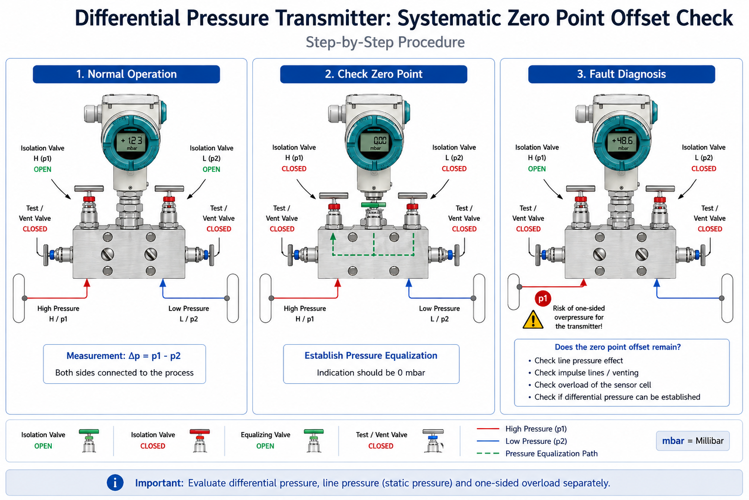
A differential pressure transmitter initially indicates the correct value of 0 mbar when depressurized. The system is then subjected to line pressure. When the high-pressure and low-pressure sides are subsequently brought back to the same pressure, however, the transmitter no longer indicates zero but, for example, several millibar of differential pressure. This quickly raises the suspicion that the sensor has been damaged or that its calibration has changed.
Such a zero point offset can indeed be caused by mechanical or metrological overload of the measuring cell. However, other causes should first be ruled out. Both process sides must actually be at the same pressure, the impulse lines must be completely filled or properly vented, and the valve position of any installed manifold must be clearly defined. With differential pressure transmitters, there is the additional factor that a high common line pressure may be present on both sides even though the actual differential pressure to be measured is very small.
Two quantities must therefore be clearly distinguished: the differential pressure that the device is intended to measure and the static or common line pressure to which the measuring cell is simultaneously exposed. There is also the possibility of one-sided overload if only one side of the transmitter is exposed to process pressure during start-up or due to an incorrect valve sequence.
If a differential pressure transmitter shows a shifted zero point after pressurization, it should therefore not be recalibrated immediately. First determine whether there is actually a permanent sensor error or whether pressure equalization, line pressure, valve position, or a previous one-sided overload is the cause.
What does a differential pressure transmitter actually measure?
A differential pressure transmitter measures the pressure difference between two process connections. In simplified terms, the high-pressure side is designated as p1 and the low-pressure side as p2. The measured value is calculated as:
Δp = p1 - p2
If, for example, the pressure on the high-pressure side is 5.100 bar and the pressure on the low-pressure side is 5.000 bar, the differential pressure is 0.100 bar or 100 mbar. If both sides are at exactly 5 bar, however, the differential pressure should ideally be 0 mbar.
This second situation is particularly interesting from a measurement perspective. Although the differential pressure is zero, the measuring cell is simultaneously exposed to a common static pressure of several bar. In applications with small differential pressure measuring ranges, the static process pressure can therefore be several orders of magnitude higher than the actual differential pressure being measured.
Distinguishing differential pressure from line pressure
With a differential pressure transmitter, differential pressure, static line pressure, and one-sided pressure loading must be considered separately. In practice, these quantities are often confused even though they have different implications for device selection and diagnostics.
| Pressure condition | Example | Meaning for the transmitter |
|---|---|---|
| Differential pressure | p1 = 5.1 bar, p2 = 5.0 bar |
Differential pressure to be measured is 100 mbar |
| Same line pressure on both sides | p1 = 20 bar, p2 = 20 bar |
Differential pressure ideally 0 mbar, but measuring cell is exposed to high static pressure |
| One-sided loading | p1 = 20 bar, p2 = 0 bar |
Measuring cell is subjected to 20 bar differential pressure |
The last case in particular can be critical. A differential pressure transmitter with a small measuring range may well be designed for a high common line pressure without necessarily being able to withstand the same pressure as a one-sided differential pressure. Permissible static pressure and permissible one-sided overload must therefore be considered separately when selecting the device.
What does zero point offset mean?
A zero point offset occurs when the transmitter no longer provides the expected zero output even though the pressure at both inputs should be identical. With a 4…20 mA transmitter, for example, this may become apparent when the output signal corresponding to zero is no longer reached exactly even though the differential pressure is equalized.
It is important to distinguish between a genuine permanent zero point offset and an apparent zero error. If the pressure conditions on both sides are not actually identical, the transmitter may still be measuring correctly. Even small pressure differences caused by liquid columns, trapped air, different impulse line filling levels, or valves that are not fully open or closed can become visible with small measuring ranges.
The zero point should therefore only be evaluated once a defined hydraulic or pneumatic condition has been established. Simply looking at two process connections that appear to be exposed to the same pressure is not always sufficient.
What is the line pressure effect?
With an ideal differential pressure sensor, an identical pressure increase on both sides would have no effect whatsoever on the differential pressure reading. Real measuring cells, however, are mechanical systems. A high common line pressure can therefore have a small influence on the zero point or output signal. This phenomenon is often referred to as the line pressure effect or static pressure effect.
How significant this effect is depends on the design of the transmitter and the requirements of the application. It can become particularly noticeable when a very small differential pressure measuring range is combined with a comparatively high process pressure. A small absolute zero point effect may then already represent a significant proportion of the actual measuring range.
It is also important to determine whether the zero point returns reproducibly after the pressure is relieved. A small specified influence while static pressure is applied must be assessed differently from a permanent shift that remains even after the pressure has been completely removed.
One-sided overload as a possible cause
One of the most important potential causes is temporary one-sided pressurization. This can occur during plant start-up, for example, if one impulse line is opened first while the opposite side of the differential pressure transmitter is still depressurized. For a short period, almost the entire line pressure is then applied to the measuring cell as differential pressure.
In a process with 20 bar line pressure and a differential pressure measuring range of only a few hundred millibar, for example, this condition can represent a very high load. Whether the transmitter can withstand it without damage depends not only on its normal measuring range but also on its design-related overload resistance.
After severe overload, the measuring cell may initially recover to a large extent. Depending on the extent of the load, however, a permanent zero point offset or a change in other measurement characteristics may remain. Therefore, after suspected overload, the zero point should not simply be readjusted without checking the measurement function more thoroughly.
How to check the manifold and pressure equalization correctly
A 3- or 5-valve manifold significantly simplifies commissioning and testing of a differential pressure transmitter. The process sides can be isolated using the shut-off valves, while an equalizing valve connects both sides of the transmitter. When pressure equalization is established correctly, the same pressure should therefore be present at both inputs.
If the device still indicates a relevant differential pressure under these conditions, diagnosis is considerably more conclusive than a test performed directly on the running process. However, it must be ensured that the equalizing valve is actually open and that no shut-off, blockage, or trapped liquid column is creating a real pressure difference.
The valve sequence during start-up and shutdown is also important. If a transmitter with a small measuring range is exposed uncontrollably to the full process pressure on only one side, exactly the condition can occur that later appears to be a sensor fault.
Influence of impulse lines, air, and liquid
In differential pressure measurement installations, the impulse lines are part of the measurement system. Different filling levels or gas bubbles can create a real hydrostatic pressure difference between the two sides. Particularly with small measuring ranges, even relatively small height differences may be sufficient to cause a visible zero point offset.
In liquid applications, both impulse lines should therefore be filled uniformly according to the intended measurement concept and should be free of unwanted gas bubbles. In gas applications, on the other hand, liquid accumulation can be problematic. Different temperatures in the two lines can also influence the measurement through changes in the density of the filling media.
An apparent sensor zero error can therefore actually originate from the installation. This is particularly true if the transmitter operates correctly when removed or when directly equalized, while the error occurs only at the process measurement point.
Systematically diagnosing zero point offset
A meaningful diagnosis begins by determining under which pressure condition the error occurs. A transmitter that already shows a shifted zero point when completely depressurized presents a different situation from a device that works correctly at atmospheric pressure and only deviates under high common line pressure.
| Observation | Possible cause | Next check |
|---|---|---|
| Zero point already shifted when depressurized | Zero drift, previous overload, or change in sensor characteristics | Establish a defined zero condition and test the transmitter |
| Correct when depressurized, shifted under equal line pressure | Static pressure effect or incomplete pressure equalization | Check direct pressure equalization via the manifold |
| Error occurs only at the installed measurement point | Impulse lines, gas bubbles, liquid columns, or valves | Check installation and filling condition |
| Zero point permanently changed after one-sided pressurization | Possible overload of the measuring cell | Check zero point, span, and repeatability |
| Reading changes reproducibly with line pressure | Possible line pressure effect | Compare behavior at several static pressure levels |
A test under several defined conditions is particularly informative. First, the zero point is checked without process pressure. Both sides can then be pressurized equally with line pressure. If the line pressure is subsequently removed again and the zero point reproducibly returns to its original value, this argues against a permanent mechanical shift of the measuring cell.
Practical example: zero point shifted after pressurization
A differential pressure transmitter is used to monitor a small pressure loss in a plant. Before commissioning, both connections are at atmospheric pressure and the transmitter provides a correct zero reading. During start-up, the high-pressure side is opened first while the low-pressure side remains isolated. For a short period, a large proportion of the process pressure therefore acts on the measuring cell from one side only.
After full commissioning, both sides are exposed to approximately the same line pressure, but the zero point has shifted. During troubleshooting, the transmitter is not immediately readjusted. Instead, both process sides are isolated and then connected through the equalizing valve. If the offset remains, the entire line pressure is subsequently reduced in a controlled manner and the zero point is checked again in the depressurized state.
If the error disappears after pressure relief and then reappears reproducibly when equal pressure is applied again, the static pressure effect or behavior under line pressure should be investigated. If, however, the zero point remains shifted even when depressurized, a permanent change caused by the previous one-sided loading is more likely. In this case, not only the zero point but also the measuring span and the overall measurement function should be checked.
The diagnosis therefore distinguishes between three fundamentally different cases: a genuinely present process differential pressure, a reversible influence of line pressure, and a possible permanent change in the measuring cell following overload.
Selecting the correct measuring range and overload resistance
When selecting a differential pressure transmitter, it is not sufficient to define only the required differential pressure measuring range. A device may measure only a few millibar or a few hundred millibar while both process connections are simultaneously exposed to a line pressure of several bar. The maximum static pressure that can occur and possible one-sided pressure conditions must therefore also be taken into account.
Particular attention must be paid to plant conditions outside normal operation. Start-up, shutdown, flushing, venting, valve operation, or maintenance work can create much less favorable pressure conditions than the regular process. A transmitter may experience only a few millibar of differential pressure for years during normal operation and then be subjected to a very high one-sided load within seconds due to an unfavorable valve operation.
Correct sizing therefore includes measuring range, maximum line pressure, permissible one-sided overload, process connection, medium, temperature, and installation concept. The planning stage should also define how the transmitter can be commissioned safely and how its zero point can be checked.
Systematic approach
- Define the normal differential pressure measuring range and the maximum expected differential pressure.
- Determine the maximum common line pressure of the application.
- Consider possible one-sided pressure conditions during start-up, shutdown, and fault situations.
- Select a differential pressure transmitter with suitable static pressure and overload resistance.
- Clearly identify and correctly connect the high-pressure and low-pressure sides.
- Check the routing, filling condition, venting, or draining of the impulse lines.
- If necessary, provide a suitable 3- or 5-valve manifold for isolation and pressure equalization.
- First check the zero point under clearly defined pressure conditions.
- If an offset is present, determine whether it occurs only under line pressure or also when depressurized.
- After suspected overload, assess not only the zero point but also the measuring span and repeatability.
Common mistakes
- Readjusting the zero point immediately: This conceals the cause of the offset. First determine whether the problem is caused by the installation, line pressure effect, or overload.
- Confusing line pressure with differential pressure: A small differential pressure measuring range does not automatically mean that the permissible static pressure is also low – the two specifications must be considered separately.
- One-sided pressurization during start-up: An unfavorable valve sequence can briefly apply almost the entire process pressure to the measuring cell as differential pressure.
- Assuming pressure equalization instead of verifying it: Closed valves, blocked impulse lines, or different liquid columns can create a real differential pressure even when the process conditions appear to be identical.
- Failing to vent or drain the impulse lines: Gas bubbles or liquid accumulation can cause significant offset values, particularly with small measuring ranges.
- Specifying only the measuring range: Maximum line pressure and permissible one-sided overload must also be considered when selecting the device safely.
- Checking only the zero point after overload: Measuring span, linearity, or repeatability may also be affected.
Suitable pressure measurement technology
Different transmitter designs are available for differential pressure measurements, ranging from very small pressure differences to demanding process applications with high static pressures. The decisive factor is that the device is suitable not only for the required differential pressure measuring range but also for the actual process pressure and any possible overload conditions.
The medium, temperature, materials, process connections, electrical output signals, and required integration into the plant should also be taken into account when selecting the device. For process measurement points, a suitable manifold can also be essential for safely isolating the transmitter, establishing defined pressure equalization, and carrying out commissioning in a controlled manner.
Suitable differential pressure transmitters, pressure sensors, and other components can be found under pressure measurement technology at ICS Schneider.
Conclusion
A zero point offset after pressurization does not automatically mean that a differential pressure transmitter is defective. First, it must be ensured that both measurement sides are actually exposed to the same pressure and that no valve position, impulse line, or hydrostatic pressure difference is causing the indicated value.
Another important influence is the common line pressure. Although the same process pressure is applied to both sides and the theoretical differential pressure is zero, static pressure can have a small influence on the zero point in high-resolution measurements. The decisive question is whether this effect is reproducible and reversible.
One-sided pressurization is particularly critical. It can occur during start-up or due to an unfavorable valve sequence and can generate a differential pressure far above the normal measuring range. If this condition exceeds the permissible overload resistance, a permanent zero point offset may remain.
For this reason, the measuring range and accuracy are not the only factors that should be considered when selecting a differential pressure transmitter. Maximum line pressure, permissible one-sided overload, process connection, impulse lines, and a safe valve strategy are equally important.
For reliable troubleshooting, the key principle is therefore: first establish genuine pressure equalization, then check the influence of line pressure, and only then determine whether a permanent overload-related or sensor-related shift is actually present.
FAQ: Zero point offset in differential pressure transmitters
Why does a differential pressure transmitter not indicate zero even though the pressure is the same on both sides?
Possible causes include incomplete pressure equalization, different liquid columns in the impulse lines, trapped air or liquid, a line pressure effect, or a permanent zero point offset following overload.
What is the line pressure effect in a differential pressure transmitter?
The line pressure effect describes the influence of a common static pressure on the zero point or output signal of the differential pressure transmitter even though, theoretically, the same pressure is applied to both sides.
What is the difference between differential pressure and line pressure?
Differential pressure is the difference between the high-pressure and low-pressure sides. Line pressure is the common pressure level at which both sides may operate. A transmitter can, for example, measure 100 mbar differential pressure while both sides are exposed to several bar of process pressure.
Can a differential pressure transmitter be damaged by one-sided pressurization?
Yes, if the resulting differential pressure exceeds the transmitter’s permissible one-sided overload. Start-up and shutdown conditions must therefore be considered during device selection.
Why is a manifold useful for differential pressure measurements?
A manifold enables controlled isolation of the process sides and pressure equalization between the high-pressure and low-pressure sides. This makes commissioning, zero point checks, and maintenance much easier to control.
Should a shifted zero point be readjusted immediately?
No. The cause of the offset should first be determined. Immediate zero adjustment may simply conceal an installation problem or a measuring cell that has been altered by overload.
How can you determine whether a zero point offset is caused by line pressure or overload?
A useful approach is to compare the depressurized condition with a condition in which the same static pressure is applied to both sides. If the offset disappears after complete pressure relief, this is more indicative of a reversible effect. If it remains even when depressurized, a permanent change in the sensor should be investigated.
Can impulse lines cause an apparent zero point error?
Yes. Different liquid columns, gas bubbles, condensate, or blockages can create a real pressure difference between the two transmitter sides even though the process pressure initially appears to be the same.
Why is the differential pressure measuring range alone not sufficient for selecting the device?
The maximum common line pressure and possible one-sided overload conditions must also be considered. A transmitter designed for very small differential pressures may simultaneously be exposed to a much higher process pressure.
What should be checked after suspected overload of a differential pressure transmitter?
In addition to the zero point, the measuring span and repeatability should be checked under defined pressure conditions. A newly adjusted zero point alone does not confirm that the measuring cell is completely undamaged.