


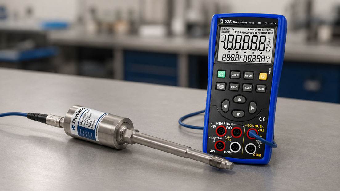
Many melt pressure sensors used in extruders, injection-moulding machines and plastics-processing systems have an internal shunt calibration function. When the corresponding calibration function is activated, the connected evaluation electronics frequently indicate a value of approximately 80% of the measuring range. For a sensor with a range of 0 to 1,000 bar, this would be 800 bar, for example.
In practice, this displayed value is often misinterpreted. During shunt calibration, an actual pressure of 800 bar is not applied to the sensor. The process diaphragm is not loaded and no real pressure is generated in the measuring channel. Instead, the electrical strain-gauge measuring bridge is unbalanced by a defined resistor. This causes the sensor to generate an output signal corresponding to the electrical signal at approximately 80% of the measuring span.
The shunt function is therefore a very useful test of the sensor, cable, connector, measuring amplifier, display and scaling. However, it does not replace a genuine pressure calibration. Mechanical damage to the process diaphragm, problems with internal pressure transmission, hysteresis, linearity deviations or an incorrectly machined mounting bore cannot be assessed reliably using the shunt signal.
This article explains how shunt calibration works in melt pressure sensors, why the 80% signal does not represent real process pressure and how the function can be used correctly during commissioning and troubleshooting. Suitable sensors can be found in the Dynisco melt pressure sensors category. Suitable test instruments for separately checking measuring amplifiers, displays and signal inputs are available in the simulators section.
Contents
- What does shunt calibration mean?
- How does the strain-gauge bridge in a melt pressure sensor work?
- What does an output signal in mV/V mean?
- How does the internal shunt resistor generate the test signal?
- Why is an 80% signal frequently used?
- Why does the signal not correspond to real process pressure?
- Which parts of the measuring chain are tested?
- What can shunt calibration not test?
- How to carry out a shunt test correctly
- Setting zero and span correctly
- Typical signal values at 80% of the measuring span
- Interpreting typical fault patterns correctly
- Difference from a genuine pressure calibration
- Testing a measuring amplifier separately with a simulator
- Practical example: Extruder indicates 760 instead of 800 bar during the shunt test
- Recommended procedure during commissioning
- Which products are suitable?
- Conclusion
- Frequently asked questions
What does shunt calibration mean?
The term shunt refers to an electrical parallel resistor. During shunt calibration, a defined resistor is connected in parallel with part of the strain-gauge measuring bridge. This changes the electrical balance of the bridge. A differential voltage is generated at the output even though the process diaphragm is not subjected to pressure.
Dynisco frequently refers to this function as R-CAL or Resistance Calibration. In many melt pressure sensors, the required resistor is already integrated into the sensor. It is activated via two separate contacts, such as CAL 1 and CAL 2, or through a corresponding function of the connected evaluation electronics.
The term calibration can be misleading in this context. The shunt test generates a known electrical reference condition. It can therefore be used to check whether the electrical measuring chain responds correctly to a defined signal. However, the sensor is not compared with a known mechanical pressure.
From a technical perspective, it is therefore primarily an electrical function, scaling and plausibility test. It is very valuable during commissioning and troubleshooting. On its own, however, it is insufficient for a complete assessment of the actual pressure measurement.
How does the strain-gauge bridge in a melt pressure sensor work?
Many conventional melt pressure sensors operate with a strain-gauge bridge. The process pressure acts on a front diaphragm that is in direct contact with the plastic melt or process medium. The pressure information is transferred through the sensor construction to the actual measuring cell.
Strain gauges are located on the measuring cell. Their electrical resistance changes slightly when they are mechanically deformed. Several of these resistors are connected to form a Wheatstone bridge. The bridge is supplied with a stable excitation voltage and produces a small differential voltage as its output signal.
With no pressure applied, the bridge is ideally in a largely balanced condition. The output signal is then close to the electrical zero point. As the process pressure rises, the mechanical load changes the resistance of the strain gauges. The bridge becomes increasingly unbalanced and the output voltage increases in proportion to the pressure.
Because the signal voltage is only a few millivolts, a conventional mV/V melt pressure sensor requires suitable evaluation electronics. These provide the bridge excitation, amplify the differential signal and scale it to the pressure measuring range.
What does an output signal in mV/V mean?
The sensitivity of many melt pressure sensors is specified in millivolts per volt. A nominal signal of 3.33 mV/V means that, at full measuring range, the sensor generates an output voltage of 3.33 mV for every volt of excitation voltage.
With a bridge excitation of 10 V, the result is:
3.33 mV/V × 10 V = 33.3 mV at 100% of the measuring range
If the same sensor is supplied with only 5 V, the full-scale signal is approximately 16.65 mV. The electrical output voltage therefore depends directly on the excitation voltage. Suitable ratiometric evaluation takes this ratio into account and nevertheless indicates the same pressure value.
A conventional voltage input is not always sufficient for this measurement. The evaluation electronics must be suitable for the small differential signal, bridge excitation, bridge resistance and connection type of the sensor. Six-wire measuring systems may additionally have sense lines for measuring the actual excitation voltage at the sensor.
How does the internal shunt resistor generate the test signal?
When the shunt function is activated, a precisely defined resistor is connected in parallel with one resistor in the measuring bridge. This electrically changes the corresponding bridge arm. The resulting bridge imbalance generates an output voltage that reproducibly corresponds to a defined proportion of the full-scale signal.
The pressure diaphragm does not move during this process. The pressure-transmitting components of the sensor are also not subjected to any mechanical load. The signal is generated exclusively by the electrical intervention in the measuring bridge.
In a sensor with internal 80% shunt calibration, the resistor is sized so that the output produces a nominal value of 80% of the full-scale signal. If the downstream display is scaled correctly for the sensor, it correspondingly indicates 80% of the pressure measuring range.
It is important to check the exact shunt value for the specific sensor series. Not every sensor necessarily uses 80%. Manufacturing tolerances, individual calibration data or different output signals may also result in a specified target value stated on the nameplate or calibration document.
Why is an 80% signal frequently used?
A test point at 80% of the measuring span lies well above zero and therefore enables a clearly recognisable span adjustment. At the same time, it remains below the full-scale endpoint. This allows displays and amplifiers to be tested without driving the electrical output directly to its maximum nominal signal.
For a sensor with a range of 0 to 1,000 bar, the nominal shunt signal corresponds to an indication of 800 bar. For a range of 0 to 500 bar, it would be 400 bar, and for 0 to 10,000 psi it would be 8,000 psi.
However, these values are only scaled indications. They mean that the electrical chain processes the shunt signal as though a pressure of 80% of the measuring range were present. In reality, the sensor should be pressureless during the test.
The expression “80% pressure” is therefore technically inaccurate. The correct term is “electrical calibration signal at 80% of the full-scale signal” or “pressure-equivalent indication at 80% of the measuring span”.
Why does the signal not correspond to real process pressure?
With real process pressure, the measuring chain begins at the front process diaphragm. The pressure must be absorbed mechanically, transmitted through the sensor and converted into deformation at the strain-gauge measuring cell. Only then is the electrical bridge signal generated.
During the shunt test, this entire mechanical path is bypassed. The resistor acts directly on the electrical bridge. As a result, an 80% value may still be indicated even if the process diaphragm is damaged, pressure transmission is impaired or the sensor channel is blocked.
| Test method | How is the signal generated? | What is subjected to load? | Meaning |
|---|---|---|---|
| Shunt calibration | Electrical unbalancing of the strain-gauge bridge | Electrical measuring chain | The sensor bridge and evaluation system respond in principle and are plausibly scaled |
| Genuine pressure test | Defined mechanical pressure applied to the process diaphragm | Complete sensor including mechanical pressure transmission | The actual pressure measurement can be compared with a reference |
| Process comparison | Real pressure during plant operation | Sensor and process installation | Plausibility under real conditions, but not automatically a traceable calibration |
The shunt signal is therefore not a substitute pressure. It is an electrical substitute value used to test the response of the measuring chain.
Which parts of the measuring chain are tested?
When an internal shunt test is carried out correctly, a large proportion of the electrical measuring chain is included. This includes the strain-gauge bridge, bridge excitation, sensor cable, connectors, measuring amplifier, display and scaling.
Depending on the setup, it may also be possible to check whether a downstream controller or PLC correctly receives the value output by the measuring amplifier. However, the additional analogue outputs and inputs must also be wired and scaled correctly.
A successful shunt test can, for example, support the following conclusions:
- The sensor is receiving an excitation voltage.
- The strain-gauge bridge responds to the connected resistance change.
- The sensor cable and connector transmit the small bridge signal.
- The measuring amplifier processes the signal.
- The configured pressure range is fundamentally compatible with the sensor signal.
- The display represents the 80% signal at the intended scale point.
- The electrical measuring chain returns to zero after the shunt is switched off.
The actual depth of the test depends on where the shunt resistor is located and how the calibration contacts are wired. If only an external simulator is connected directly to the amplifier input, the sensor and sensor cable are not included in the test.
What can shunt calibration not test?
Shunt calibration does not test a real mechanical pressure load. Several important fault areas therefore remain undetected.
The following cannot be assessed reliably:
- Condition and elasticity of the process diaphragm,
- mechanical damage caused by cleaning tools,
- wear or abrasion of the diaphragm,
- pressure transmission through the capillary or fill medium,
- leaks within the pressure-transmitting system,
- linearity across the complete pressure range,
- hysteresis with increasing and decreasing pressure,
- actual sensitivity under mechanical load,
- transmission behaviour during rapid pressure changes,
- influence of process and sensor temperature on the real measurement,
- blocked or incorrectly machined mounting bores.
A sensor may pass the shunt test and still measure incorrectly under real pressure. Conversely, a mechanically intact sensor may appear faulty during the shunt test if the evaluation electronics are scaled incorrectly or the wiring is defective.
How to carry out a shunt test correctly
Before starting, it must be ensured that the plant is in a safe condition. For a meaningful shunt test, the sensor should be pressureless. The calibration contacts must not be bridged while an unknown or high process pressure is present unless the operating instructions for the specific sensor specify a different procedure.
A practical procedure consists of the following steps:
- Connect the sensor, measuring amplifier and display in accordance with the wiring diagram.
- Set the correct excitation voltage, sensor sensitivity, measuring range and unit.
- Wait for the specified warm-up and temperature stabilisation time.
- Ensure that no pressure is actually applied to the sensor.
- Check the display zero point and, if necessary, adjust it in accordance with the manufacturer’s instructions.
- Activate the shunt function using the designated CAL contacts or the evaluation instrument.
- Compare the displayed value with the sensor target value.
- If permitted, adjust the span of the evaluation electronics to the specified shunt value.
- Deactivate the shunt function.
- Check whether the display returns stably to zero.
- If necessary, check the zero point and shunt value again, because the adjustments may influence one another.
The CAL contacts may only be connected in accordance with the sensor wiring diagram. An incorrect connection to excitation or signal lines can cause malfunctions or damage. An arbitrary additional resistor must also not be used if the sensor already contains an internal calibration resistor.
Setting zero and span correctly
Zero and span are two different adjustments. The zero point determines the value indicated when no pressure is applied to the sensor. The span determines how strongly the sensor signal is amplified and scaled across the measuring range.
The correct procedure always begins with a plausible zero point. Only then is the shunt signal activated and the span checked. If the span is adjusted while a significant zero error is already present, the 80% value may appear correct even though the entire characteristic curve is offset.
After span adjustment, the shunt must be switched off and the zero point checked again. In analogue amplifiers, zero and span adjustments can influence each other slightly. Several adjustment steps may therefore be required.
Particular care is required with potentiometers located directly on the sensor. Zero or span adjusters may only be changed in accordance with the instructions for the respective sensor series. Uncontrolled adjustment can alter the original factory calibration and make subsequent fault analysis more difficult.
In installed melt pressure sensors, the zero point may change due to mounting stress and temperature. The required zero adjustment should therefore be performed under the mechanical and thermal conditions specified by the manufacturer. However, a zero adjustment must not compensate for an actual residual or process pressure.
Typical signal values at 80% of the measuring span
The expected electrical signal depends on the sensor output type. For a conventional mV/V sensor, the actual bridge excitation must also be taken into account.
| Output signal | Signal at 0% | Signal at 100% | Nominal 80% shunt signal |
|---|---|---|---|
| 3.33 mV/V with 10 V excitation | close to 0 mV | 33.3 mV | 26.64 mV |
| 2 mV/V with 10 V excitation | close to 0 mV | 20 mV | 16 mV |
| 0–10 V | 0 V | 10 V | 8 V |
| 4–20 mA | 4 mA | 20 mA | 16.8 mA |
A common misconception must be considered with a 4–20 mA signal: 80% of the measuring range does not correspond to 16 mA. The usable measuring span is 16 mA, from 4 to 20 mA. Eighty per cent of this value is calculated and then added to the zero signal:
4 mA + 0.8 × 16 mA = 16.8 mA
The table shows typical calculated values. However, the specifications of the actual sensor are decisive for the real test. Depending on the series, individual calibration and version, the specified target value may differ.
Interpreting typical fault patterns correctly
| Observation | Possible cause | Useful test |
|---|---|---|
| Zero point is correct, but the shunt value is significantly too low | Gain too low, incorrect sensor sensitivity, insufficient excitation, cable or contact problem | Check the excitation voltage at the sensor, mV signal and amplifier setting |
| Zero point is correct, but the shunt value is too high | Gain too high, incorrect measuring range or incorrect scaling | Compare the sensor data with the display range settings |
| Shunt value is correct, but the real process value appears implausible | Mechanical sensor fault, diaphragm damage, installation problem, blocked measuring bore or incorrect process comparison | Check using a genuine pressure test and inspect the mechanical installation |
| Nothing changes when the shunt is activated | CAL contacts not connected, incorrect pin assignment, cable break or no shunt function | Check the wiring diagram and continuity of the calibration cable |
| A high value remains after the shunt is switched off | CAL contact still closed, short circuit, faulty evaluation electronics or unstable sensor | Disconnect the calibration line and measure the raw signal |
| Shunt value fluctuates significantly | Unstable excitation, loose connector, EMC interference, cable problem or amplifier fault | Check the excitation, screening, connectors and signal directly at the input |
| Display indicates 800 bar although the sensor is pressureless | Normal condition with an active 80% shunt | Deactivate the shunt and check the return to zero |
For targeted troubleshooting, it is useful to measure the raw signal directly. With a 3.33 mV/V sensor and 10 V excitation, approximately 26.64 mV should be present when the 80% shunt is activated. If this signal is correct but the display is incorrect, the fault is probably in the gain or scaling. If the raw signal is already incorrect, the sensor, excitation, cable and shunt activation must be checked.
Difference from a genuine pressure calibration
During a genuine pressure calibration, the melt pressure sensor is subjected to a defined pressure. This pressure is measured simultaneously using a suitable reference instrument. The sensor indication and reference are compared at several test points.
A complete test can, for example, include points at 0, 25, 50, 75 and 100% of the measuring range. Increasing and decreasing series also enable hysteresis to be assessed. The deviations can be used to determine whether zero, span, linearity and repeatability remain within the required limits.
Mechanical pressure calibration of melt pressure sensors is demanding because of the high measuring ranges and special process connections. The pressure source, reference, adapters and transmission medium must be suitable for the measuring range and the sensor. Safe pressure generation and controlled depressurisation are also required.
Shunt calibration answers the question: “Does the electrical measuring chain process the defined test signal correctly?”
Pressure calibration, by contrast, answers the question: “Does the sensor indicate the correct value when a genuinely known pressure is applied?”
The two tests complement one another, but they do not replace each other.
Testing a measuring amplifier separately with a simulator
During troubleshooting, it may be useful to separate the sensor from the evaluation electronics. A suitable simulator generates a defined mV or mV/V signal and is connected to the measuring amplifier or display instead of the sensor.
The ICS 02S simulator for Pt100, RTD, TC and mV/V can measure and generate defined low-level signals. It can therefore be used to check whether a suitable input indicates the correct pressure value at specified signal values.
A distinction must be made between simple voltage simulation and complete strain-gauge bridge simulation. Some measuring amplifiers do not only expect a differential voltage, but also monitor bridge resistance, excitation lines or sense connections. In such cases, it must be checked whether the simulator used can fully reproduce the required sensor configuration.
For melt pressure transmitters with a 4–20 mA output, the UPS4E loop calibrator is suitable for measuring and simulating the loop signal. This can be used to check whether the display and PLC correctly process, for example, 4 mA as the lower range value, 16.8 mA as the 80% value and 20 mA as the upper range value. This electrical test also does not replace applying real pressure to the transmitter.
Practical example: Extruder indicates 760 instead of 800 bar during the shunt test
A melt pressure sensor with a measuring range of 0 to 1,000 bar is installed on an extruder. The connected display indicates 0 bar when the plant is pressureless. After the internal 80% shunt calibration is activated, however, it indicates only 760 bar.
The melt pressure sensor is initially suspected. A direct measurement of the bridge signal, however, shows that the sensor provides the specified mV value when the shunt is activated. The sensor bridge, shunt resistor and cable are therefore fundamentally plausible.
When the display is checked, it is found that an insufficient input sensitivity or incorrect gain factor has been configured. The display span is corrected in accordance with the manufacturer’s instructions. It then indicates 800 bar with the shunt activated and returns to 0 bar after it is switched off.
The electrical measuring chain is therefore adjusted correctly. However, this does not yet prove that the sensor measures correctly across the full range under real pressure. Because the plant had previously shown implausible process values, an additional mechanical pressure test is arranged.
This example illustrates the actual benefit of the shunt function: it helps to narrow down the area in which the fault lies. It can help distinguish whether the deviation is more likely to be found in the sensor bridge and wiring, the display scaling or the mechanical pressure path.
Recommended procedure during commissioning
When commissioning a new or replacement melt pressure sensor, the mechanical and electrical tests should be considered separately.
- Compare the sensor series, pressure range, output signal and pin assignment with the plant.
- Check the mounting bore, thread, installation depth and condition of the process diaphragm.
- Install the sensor using the specified tightening torque and without mechanical stress.
- Check the excitation voltage and sensor input of the evaluation electronics.
- Check the zero point with the sensor safely depressurised.
- Activate the internal shunt function and compare the target value with the data sheet or calibration documents.
- Deactivate the shunt and check the return to zero.
- Compare the scaling of the display, controller and PLC.
- If required, carry out a genuine pressure test using a suitable reference.
- Document the results, settings and sensor data.
Particularly after replacing a sensor, it must not be assumed that every sensor with the same thread is automatically electrically compatible. Sensitivity, bridge resistance, excitation voltage, pin assignment, shunt contacts and pressure range must also match.
Which products are suitable?
The Dynisco melt pressure sensors category includes different sensor series for extrusion, injection moulding, compounding, rheometers and other plastics-processing applications. Many models have an internal shunt calibration function, although the version, output signal and target value of the respective series must be checked.
Conventional mV/V sensors are particularly suitable for plants that already have a compatible melt pressure controller or strain-gauge measuring amplifier. They provide a small bridge signal and require stable excitation and suitable amplification.
The simulators category contains instruments for targeted testing of electrical measurement and signal inputs. The ICS 02S can generate defined mV or mV/V signals and therefore help to assess the display and measuring amplifier independently of the installed melt pressure sensor.
A genuine pressure calibration additionally requires a suitable pressure source, suitable high-pressure adapters and a sufficiently accurate reference measuring instrument. The complete test setup must be rated for the pressure range of the melt pressure sensor.
Conclusion: The 80% signal tests the electrical chain, not the real pressure
Internal shunt calibration is an effective function for commissioning and troubleshooting melt pressure sensors. A defined resistor electrically unbalances the strain-gauge bridge. The connected display should then indicate a specified proportion of the measuring span, nominally 80% for many Dynisco sensors.
During the shunt test, an indication of 800 bar for a sensor with a range of 0 to 1,000 bar does not mean that 800 bar is actually applied to the process diaphragm. It merely shows that the electrical measuring chain is processing a signal corresponding to the output signal at 80% of the measuring range.
The test can fundamentally assess the sensor bridge, excitation, cable, connector, amplifier and scaling. Mechanical diaphragm damage, pressure-transmission problems, linearity, hysteresis and actual pressure sensitivity are not fully tested.
For a reliable assessment, shunt calibration should therefore be understood as a supplementary electrical function test. If it must be demonstrated that the sensor measures the real process pressure correctly, a pressure calibration using a suitable pressure source and traceable reference is required.
Frequently asked questions about shunt calibration of melt pressure sensors
What does internal 80% shunt calibration mean?
An internal resistor unbalances the strain-gauge bridge so that an electrical output signal nominally equal to 80% of the full-scale signal is generated. A correctly scaled display then indicates 80% of the pressure measuring range.
Is 80% of the nominal pressure actually applied during the shunt test?
No. The sensor should be pressureless during the test. The signal is generated electrically and not by loading the process diaphragm.
Does the shunt test replace a pressure calibration?
No. It primarily tests the electrical measuring chain. To assess the actual pressure measurement, the sensor must be subjected to known pressure values and compared with a reference.
Which signal does a sensor with 3.33 mV/V provide during the 80% test?
With 10 V bridge excitation, the full-scale signal is 33.3 mV. Eighty per cent of this corresponds nominally to 26.64 mV. With a different excitation voltage, the absolute mV value changes proportionally.
Why does a 4–20 mA transmitter not indicate 16 mA at 80%?
The measuring range begins at 4 mA. Eighty per cent of the 16 mA span corresponds to 12.8 mA. Adding the 4 mA zero signal produces a value of 16.8 mA.
What does it mean if the shunt value is correct but the process value appears incorrect?
In this case, the electrical measuring chain is fundamentally plausible. However, the fault may still be located at the process diaphragm, internal pressure transmission, mounting bore, temperature or actual process condition.
May the shunt function be activated while the process is running?
The intended procedure depends on the sensor and evaluation electronics. For an unambiguous adjustment, the test should generally be performed in a safely known, preferably pressureless condition and in accordance with the manufacturer’s instructions.
Can an mV simulator completely replace a melt pressure sensor?
Not always. A simple simulator can generate a defined voltage signal for the amplifier input. Some inputs additionally expect a specific bridge resistance, excitation lines or sense connections. The test setup must therefore be compatible with the evaluation electronics.