


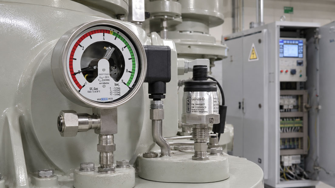
In SF6-insulated switchgear, circuit breakers and other gas-filled high-voltage equipment, an adequate gas filling is essential for the intended operation of the installation. In practice, however, the condition of the gas compartment is often assessed too quickly on the basis of a single pressure value. This is where a fundamental problem arises: The pressure of SF6 changes not only when gas is lost, but also with temperature.
When the temperature falls, the measured pressure decreases even if the gas compartment is completely gas-tight and the amount of gas contained within it has not changed. When the temperature rises, the pressure increases accordingly. A pressure measurement alone can therefore result in false alarms, incorrect refilling decisions or delayed detection of actual gas losses.
For a reliable condition assessment, the influence of temperature must be calculated out of the measured value or compensated by means of a suitable mechanical measuring principle. Gas density monitors and gas density sensors therefore do not simply indicate the pressure currently present. They include the gas temperature in the assessment and display, for example, a pressure referenced to 20 °C or the calculated gas density directly.
This article explains the relationship between pressure, temperature and gas density, shows the differences between mechanical and electronic measuring systems, and describes what must be considered regarding warning stages, alarm limits, commissioning and leakage monitoring.
Table of contents
- Why gas density is the decisive operating parameter
- Relationship between SF6 pressure and temperature
- How temperature compensation works
- What does filling pressure referenced to 20 °C mean?
- Understanding warning, alarm and shutdown stages correctly
- Mechanical and electronic gas density measurement compared
- How actual leaks can be detected
- Typical misinterpretations in practice
- Practical example: Pressure drop due to cooling or leakage?
- What to consider when selecting the measuring system
- Installation, commissioning and signal testing
- Which measuring instruments / products are suitable?
- Conclusion
- Frequently asked questions about temperature-compensated SF6 gas density measurement
Why gas density is the decisive operating parameter
In simplified terms, gas density describes the mass of gas contained within a specific volume. In a closed and dimensionally stable gas compartment, the density remains largely constant as long as no gas escapes and the vessel volume does not change significantly.
Pressure behaves differently. It responds directly to changes in temperature. When the enclosed SF6 is heated, the gas molecules move more vigorously and the pressure increases. When it cools, the pressure decreases. The mass of gas contained within the compartment can remain unchanged during this process.
For condition monitoring of a gas-insulated installation, the pressure currently being measured is therefore not the only decisive factor. What matters is whether the intended amount of gas or gas density is still present. Only a temperature-compensated measured value makes it possible to distinguish a thermally induced pressure change from a possible gas loss.
This does not mean that the current gas pressure is unimportant. It can be a valuable additional measured variable for diagnostics, maintenance and plausibility checks. For long-term monitoring of the filling condition and the definition of warning or alarm stages, however, the compensated gas density or the pressure referenced to a reference temperature is the more meaningful variable.
Relationship between SF6 pressure and temperature
The relationship between pressure and temperature can initially be explained using the general gas law. With an unchanged amount of gas and a constant volume, the absolute pressure increases approximately in proportion to the absolute temperature. The temperature must be considered in kelvin.
For a simple estimate, the following applies:
p2 ≈ p1 × T2 / T1
This simplified relationship illustrates the thermal influence, but it does not replace device-specific SF6 compensation. Particularly at higher pressures, low temperatures or with gas mixtures, real-gas behaviour must be taken into account. Depending on the design, electronic gas density sensors therefore operate with stored characteristic curves, equations of state or calculation methods configured specifically for the gas being used.
The following example shows how strongly the pressure in an unchanged gas compartment can vary due to temperature alone. The starting point is an example absolute pressure of 6.00 bar at 20 °C. The values are intended only to illustrate the physical order of magnitude.
| Gas temperature | Approximate absolute pressure | Gas mass in the closed vessel | Assessment |
|---|---|---|---|
| −20 °C | approx. 5.18 bar abs. | unchanged | A significant pressure drop may be caused entirely by temperature |
| 0 °C | approx. 5.59 bar abs. | unchanged | Lower pressure without necessarily indicating gas loss |
| 20 °C | 6.00 bar abs. | unchanged | Reference condition in this example |
| 40 °C | approx. 6.41 bar abs. | unchanged | Pressure increase due to heating |
| 60 °C | approx. 6.82 bar abs. | unchanged | Further pressure increase without additional gas filling |
If, in this example, a conventional pressure switch were to trip at 5.5 bar abs. regardless of temperature, normal winter cooling could already trigger an alarm. A temperature-compensated gas density monitor, by contrast, would recognise that the pressure drop corresponds to the lower temperature and that the gas density still matches the intended filling condition.
In the actual installation, the pressure type, atmospheric conditions, specific gas, gas mixture, nominal filling pressure and permissible temperature range must also be considered. Absolute and gauge pressure values must not be confused.
How temperature compensation works
With temperature compensation, the currently measured gas condition is converted to a defined reference condition. A pressure value referenced to a gas temperature of 20 °C is frequently used for this purpose. Alternatively, the gas density can be output directly in a unit such as grams per litre.
The technical implementation depends on the measuring instrument used. In mechanical gas density monitors, a temperature-dependent compensation element can correct the movement of the pressure measuring system. As a result, the pointer and switching contacts do not follow the instantaneous pressure alone, but a temperature-compensated value.
Another mechanical option is the reference chamber principle. In this design, the behaviour of the process gas is compared with a defined, hermetically sealed reference gas. When the temperature changes, comparable thermal effects act on the process and reference sides. An actual density loss in the monitored gas compartment, however, produces a permanent difference.
Electronic gas density sensors usually measure at least the gas pressure and temperature. Internal electronics use these values to calculate the gas density or a compensated pressure. Depending on the sensor type, the calculation may be based on a simple characteristic curve, a real-gas equation of state or a mathematical model specifically adapted to the gas mixture.
It is essential that the measured temperature represents the actual thermal condition of the gas as accurately as possible. A temperature sensor influenced by direct sunlight, a control cabinet heater or adjacent warm components may measure a different temperature from the gas in the vessel. Temporary deviations may then occur even though the pressure sensor itself is functioning correctly.
Thermal delays may also occur with large gas compartments, long connecting lines or rapid temperature changes. The housing, connection block, piping and gas volume do not always reach the same temperature at the same time. Individual short-term jumps in measured values should therefore not be interpreted as leakage without a plausibility check.
What does filling pressure referenced to 20 °C mean?
The filling pressure of an SF6 installation is often specified for a defined reference temperature, for example as the filling pressure at 20 °C. This value does not necessarily describe the pressure that must be measured directly at the connection at every possible ambient temperature.
If the gas temperature is below 20 °C, the actual uncompensated pressure is lower. At a temperature above 20 °C, it is correspondingly higher. A temperature-compensated measuring instrument converts the current condition back to the reference condition. This makes it possible to compare measurements taken in summer and winter.
Displaying a pressure referenced to 20 °C simplifies assessment because the operator does not have to perform a separate temperature correction for every measurement. If the compensated value remains stable, this initially indicates that the gas filling is unchanged. If the compensated value decreases over a longer period, this may indicate a gas loss or another deviation in the measuring system.
During commissioning, it must be documented clearly whether the display represents the current pressure, absolute pressure, gauge pressure, gas density or a compensated pressure referenced to 20 °C. Incorrect interpretations frequently arise because different measured variables are grouped under the same designation of “SF6 pressure”.
Understanding warning, alarm and shutdown stages correctly
Gas density monitors can be equipped with several electrical switching contacts. This allows different responses to be initiated before a critical condition is reached. The permissible limits and required system response must be derived from the switchgear manufacturer’s specifications and the operator’s protection concept.
A typical sequence may consist of a pre-warning, an alarm stage and an additional interlocking or shutdown function. However, these terms are not defined identically for every installation. A limit value must therefore not be adopted solely on the basis of a general percentage figure.
| Stage | Possible meaning | Typical operational response |
|---|---|---|
| Normal range | Gas density is within the intended operating range | Normal system operation and regular trend monitoring |
| Pre-warning | First defined drop below the compensated filling condition | Check the measured value, evaluate the trend and plan maintenance |
| Alarm | Further density loss or drop below an operationally critical limit | Investigate the cause and initiate measures in accordance with the system concept |
| Interlock or shutdown | Drop below a minimum condition defined by the system manufacturer | Block switching operations or take the installation out of service in a controlled manner |
When defining switching points, measuring accuracy, switching hysteresis, the permissible device tolerance and possible dynamic temperature effects must be taken into account. Warning and alarm limits must not be so close together that normal measurement fluctuations cause repeated contact changes.
Correct assignment of the contacts in the control cabinet is equally important. A technically correctly adjusted gas density monitor does not provide adequate protection if warning and alarm contacts are interchanged, normally closed and normally open contacts are evaluated incorrectly, or the signal is not scaled unambiguously in the PLC.
Mechanical and electronic gas density measurement compared
Whether a mechanical gas density monitor or an electronic gas density sensor is more suitable depends on the required monitoring strategy. Both systems can monitor temperature-compensated gas density, but they differ in terms of display, signal output, diagnostics and integration.
| Measuring system | Typical functions | Particularly suitable for | Points to consider |
|---|---|---|---|
| Mechanical gas density monitor | Local display and defined switching contacts | Robust on-site monitoring with direct warning and alarm functions | No continuous trend curve without an additional electrical measured-value output |
| Electronic gas density sensor | Continuous measured value, for example 4–20 mA or digital communication | Remote monitoring, data logging, control system integration and trend analysis | Power supply, scaling and signal processing must be designed correctly |
| Mechatronic or hybrid system | Local display, contacts and an additional electrical output signal | Applications combining local operational safety with central condition monitoring | Additional functions require clear documentation of all measuring and switching outputs |
Mechanical gas density monitors have the advantage that the display and switching function are located directly at the gas compartment. Depending on the design, they do not require separate measured-value processing by a PLC for the local indication and mechanical contacts. They are therefore particularly suitable for clearly defined warning and alarm tasks.
Electronic gas density sensors provide a continuous measured value. This makes it possible not only to detect whether a limit has already been exceeded, but also to assess how quickly the compensated value is changing. A slow but steady decrease may therefore be detected before a switching contact reaches its fixed warning stage.
Depending on the design, digital systems can provide additional values such as current pressure, compensated pressure, gas temperature or gas density. This information improves diagnostics, but it must be interpreted correctly. A greater number of measured values does not automatically result in a better condition assessment if units, reference temperatures and control-system scaling are not documented clearly.
How actual leaks can be detected
A single low pressure value is not yet clear evidence of an SF6 leak. Likewise, a currently high pressure in warm conditions does not prove that the gas compartment is adequately filled. The trend of the temperature-compensated measured value over a longer period is more meaningful.
If the pressure referenced to 20 °C remains stable despite changing ambient and gas temperatures, this indicates a largely constant gas filling. If the compensated value decreases continuously, however, the cause must be investigated. Possible causes are not limited to leaks in the gas compartment. A valve that is not fully open, a leaking connecting line, an unsuitable seal, incorrect temperature measurement or a fault in the measuring instrument can also influence the measured value.
Gas density measurement can detect a possible gas loss or make it visible as a trend. However, it does not automatically locate the precise leak. Additional tightness tests, suitable SF6 leak detectors or manufacturer-specific test methods are required for localisation.
Where possible, comparable operating conditions should be considered when evaluating trends. Short-term thermal transitions, for example after direct sunlight, load changes, maintenance work or opening an equipment room, can temporarily cause differences between the gas temperature and sensor temperature.
The resolution of the recorded signal also plays a role. Very coarse PLC scaling can conceal small but relevant long-term changes. At the same time, normal signal noise from a high-resolution sensor must not be interpreted as an apparent microleak. For a reliable assessment, measurement uncertainty, long-term stability and operational tolerances must be considered together.
Typical misinterpretations in practice
One of the most common misinterpretations is comparing the current pressure directly with the nominal filling pressure specified at 20 °C. If the measurement is taken at a significantly lower gas temperature, for example, the actual pressure must be below the 20 °C value. This is physically normal at first.
Another error is using a conventional pressure transmitter with a fixed pressure alarm without taking temperature into account. Such a system can work if pressure and temperature are measured separately and processed in the controller using a suitable gas-specific model. A simple pressure limit alone, however, is not genuine gas density monitoring.
It is equally problematic to use the outside temperature as a general substitute for the gas temperature. A gas compartment can be significantly warmer or colder than the freely measured ambient air due to direct sunlight, operating losses, load conditions or adjacent components.
With gas mixtures, the same compensation characteristic as for pure SF6 must not be used automatically. Different gases have different thermodynamic properties. The measuring instrument or calculation must be designed or configured for the specific composition.
Additional sources of error include confusing absolute and gauge pressure, using incorrect units, applying unsuitable PLC scaling or assigning warning and alarm contacts incorrectly. A subsequently replaced measuring instrument must also not be selected solely on the basis of its connection thread and measuring range. The compensation method, gas type, reference temperature and switching points must also match.
Practical example: Pressure drop due to cooling or leakage?
A gas-insulated switchgear installation has an intended absolute filling pressure of 6.00 bar at 20 °C, for example. In summer, a current pressure above 6.00 bar is measured at an elevated gas temperature. In winter, the current pressure decreases significantly at a low gas temperature.
On a cold morning at approximately −10 °C, a conventional pressure gauge indicates only around 5.4 bar abs. If this value is considered in isolation, it may appear that approximately 0.6 bar of gas pressure is missing. In reality, the difference may be caused almost entirely by cooling.
A temperature-compensated gas density monitor converts the current condition back to the reference temperature. If it continues to display a compensated value of approximately 6.00 bar at 20 °C, this measured value does not indicate a loss of gas mass.
Several months later, however, the compensated value is only 5.75 bar referenced to 20 °C. At the same time, the trend recording from an electronic gas density sensor shows a slow and largely continuous decrease. This change can no longer be explained solely by daily temperature fluctuations.
The measuring instrument, connection fitting, valve position, gas compartment and possible sealing points must now be checked systematically. In this case, the gas density measurement provides a substantiated indication of a deviation, but it does not replace subsequent leak localisation and assessment by qualified personnel.
The example shows why comparing individual instantaneous pressure values is insufficient. Only temperature compensation and analysis of the trend over time make it possible to distinguish reliably between normal thermal behaviour and a possible gas loss.
What to consider when selecting the measuring system
The selection of a gas density monitor or gas density sensor begins with the specific installation. Statements such as “for SF6” or “measuring range up to 10 bar” are not sufficient for a reliable design. At a minimum, information is required about the gas, filling pressure, reference temperature, permissible temperature range and desired monitoring function.
For pure SF6, a corresponding standard compensation can be used. For alternative insulating gases or gas mixtures, it must be checked whether the instrument can be designed for the precise composition. Even a different mixture can mean that the pressure-temperature characteristic no longer matches the device calibration.
It must then be clarified whether only a local display is required or whether fixed switching points, a continuous analogue signal or a digital interface are needed. A gas density monitor with contacts may be sufficient for a simple pre-warning. A gas density sensor is often better suited to trend analysis, central monitoring and condition-based maintenance.
Other important selection criteria include:
- Gas type and exact composition of a possible gas mixture
- Nominal filling pressure and permissible operating range
- Reference temperature
- Absolute or gauge pressure reference
- Minimum and maximum operating temperature range
- Number and function of the required switching contacts
- Required output signal, for example 4–20 mA or digital communication
- Requirement for a local display
- Requirements regarding measuring accuracy, long-term stability and switching hysteresis
- Process connection, sealing concept and permissible connection volume
- Mounting position, vibration, ingress protection and ambient conditions
- Possibility of functional testing or recalibration without removal
- Compatibility with PLC, protection equipment and control system
The final selection should always be made on the basis of the specific switchgear installation and the system manufacturer’s requirements. An existing gas density monitor must not be replaced by an instrument with an apparently similar measuring range without a technical assessment.
Installation, commissioning and signal testing
Even a correctly selected gas density measuring instrument can provide incorrect or difficult-to-interpret values if it is installed unfavourably. The process connection must provide a reliable connection to the monitored gas compartment. Shut-off valves must be in the intended operating position, and additional connecting lines must not create impermissible dead volumes or potential leakage points.
The mounting position should allow the measuring instrument to detect the thermal condition of the gas compartment as accurately as possible. Direct sunlight, local heaters, warm cable rooms or significantly different ambient temperatures can influence temperature measurement. In certain installations, remote temperature measurement or a special connection concept may be appropriate.
During electrical commissioning, the measuring range, unit and signal assignment must be documented completely. With a 4–20 mA output, for example, it must be defined clearly which density or compensated pressure value corresponds to 4 mA and which value corresponds to 20 mA. A PLC display in bar is incorrect if the sensor is actually scaled in grams per litre and no correct conversion has been configured.
Switching contacts should not be checked only for continuity. The complete signal chain from the gas density monitor through terminals, wiring and protection relays to the visualisation or system response must be tested. The test connections and procedures specified by the manufacturer must be used.
For a plausibility check, it is helpful to consider the current pressure, gas temperature and compensated measured value together. If the current pressure changes significantly with temperature while the compensated value remains stable, the compensation is operating plausibly in principle.
Testing, installation and maintenance work on SF6 systems must only be carried out with suitable equipment and by appropriately qualified personnel. Connections must not be opened in an uncontrolled manner. The measuring and servicing concept should be designed to avoid unnecessary gas emissions.
Which measuring instruments / products are suitable?
Gas density monitors are suitable for local monitoring of SF6 gas compartments with fixed warning and alarm limits. Depending on the design, they combine a temperature-compensated on-site display with one or more electrical switching contacts.
Gas density monitors are particularly useful when a clearly defined response is required after specific density stages are crossed. Depending on the instrument, different measuring principles, housing sizes, process connections, contact configurations and testing options can be implemented.
SF6 gas density sensors are available for continuous remote monitoring, trend analysis and integration into PLC or control systems. Depending on the design, they measure pressure and temperature and use these values to calculate the compensated gas density or the pressure referenced to a defined temperature.
Electronic gas density sensors can provide an analogue 4–20 mA signal or digital measured values, for example. This makes it possible not only to monitor fixed limits, but also to evaluate gradual changes over weeks, months or years.
For a gas density sensor with a 4–20 mA output, the UPS4E loop calibrator can be used as a supplementary instrument for electrical commissioning and troubleshooting. It is suitable, for example, for checking the loop current, verifying PLC scaling or simulating an analogue input signal.
However, the UPS4E does not test the actual SF6 gas density and does not replace a gas density reference system, tightness test or leakage test. It is solely a tool for testing the electrical 4–20 mA signal loop.
ICS Schneider Messtechnik assists with the selection of a suitable measuring system on the basis of the gas type, filling pressure, reference temperature, switching points, process connection and required signal output. For replacement instruments, the data of the existing instrument, the nameplate, terminal assignment and, where possible, the original system documentation should also be provided.
Conclusion: The influence of temperature must be considered for reliable SF6 monitoring
The pressure in a closed SF6 gas compartment changes with temperature. A low pressure is therefore not automatically an indication of a leak, and a high pressure does not automatically confirm that the gas filling is adequate.
For assessing the actual filling condition, the temperature-compensated gas density or a pressure referenced to a defined temperature is decisive. Gas density monitors perform this task locally and can operate defined warning or alarm contacts. Electronic gas density sensors additionally provide continuous measured values for remote monitoring, data logging and trend analysis.
A reliable solution, however, requires more than a suitable measuring range. The gas type, gas mixture, reference temperature, pressure type, switching points, installation conditions and signal processing must be matched to the specific switchgear installation. The final suitability of a measuring system should therefore always be verified on the basis of the specific application data and the system manufacturer’s requirements.
Frequently asked questions about temperature-compensated SF6 gas density measurement
Why is a conventional pressure gauge not sufficient for SF6 monitoring?
A conventional pressure gauge indicates the current pressure. This changes both when gas is lost and when the gas temperature changes. Without temperature compensation, it is therefore not possible to determine clearly whether gas has actually escaped.
Does the SF6 gas density change when the temperature changes?
In a closed and dimensionally stable gas compartment, the gas mass and therefore approximately the average density remain constant as long as no gas escapes. The pressure, however, changes with temperature. Gas density measurement compensates precisely for this thermal pressure influence.
What does an SF6 filling pressure at 20 °C mean?
The value describes the gas condition referenced to a temperature of 20 °C. At a lower actual gas temperature, the pressure measured directly may be below this value even though no gas is missing. A temperature-compensated instrument converts the current condition back to 20 °C.
What is the difference between current pressure and compensated pressure?
The current pressure is the pressure present in the gas compartment at the actual temperature. The compensated pressure is converted to a defined reference temperature and therefore allows a comparison of the filling condition that is less dependent on temperature.
What is the difference between a gas density monitor and a gas density sensor?
A gas density monitor typically has a local display and electrical contacts for warning or alarm stages. A gas density sensor, by contrast, provides a continuous electrical measured value, for example via 4–20 mA or a digital interface.
Can a conventional pressure transmitter be used for gas density monitoring?
A pressure transmitter alone does not provide temperature-compensated gas density. Gas density monitoring is only possible if the actual gas temperature is additionally measured and the pressure is compensated using a suitable calculation method adapted to the gas.
How does a gas density monitor detect a leak?
The gas density monitor compensates for the influence of temperature on pressure. If the compensated value drops below a defined limit, a switching contact can trigger a warning or alarm. The instrument therefore detects a loss of density, but it does not automatically locate the leak.
How can a temperature change be distinguished from a gas loss?
With a temperature change alone, the current pressure changes while the compensated measured value remains largely stable. In the event of an actual gas loss, the pressure referenced to the reference temperature or the calculated gas density also decreases.
Why is trend recording useful?
Trend recording shows whether the compensated measured value remains stable over a longer period or decreases gradually. This allows slow changes to be detected before a fixed warning contact is reached.
Can SF6 gas density monitors also be used for alternative insulating gases?
This is only possible if the measuring instrument has been expressly designed and compensated for the relevant gas or gas mixture. The thermodynamic properties of different gases vary. A characteristic designed for pure SF6 must not be used for another gas without verification.
Why must the same compensation as for pure SF6 not be used for gas mixtures?
Gas mixtures have a different pressure-temperature characteristic from pure SF6. The composition, mixing ratio and operating range influence the calculation. The measuring system must therefore be adapted to the specific gas mixture.
How are warning and alarm limits defined?
The limits are derived from the nominal filling condition, the permissible operating limits and the protection concept of the specific installation. The switchgear manufacturer’s specifications are decisive. General percentage values should not be adopted without verification.
Can a 4–20 mA gas density signal be tested with a loop calibrator?
Yes. A suitable loop calibrator can be used to measure the loop current and test the processing in the PLC or control system. Defined input signals can also be simulated. However, this only tests the electrical signal path and not the physical gas density measurement.
What errors can occur when scaling the signal in the PLC?
Typical errors include reversed lower and upper range values, incorrect units, confusion between gas density and compensated pressure, or incorrect assignment of 4 mA and 20 mA. The scaling must be compared with the data sheet and the specific device configuration.
Does atmospheric pressure play a role?
This depends on the measuring principle and the pressure reference used. With gauge-pressure measurements, atmospheric pressure can influence the displayed value. Hermetically sealed or absolute-pressure measuring systems can reduce this influence by design or take it into account in the compensation.
Can a gas density sensor determine the precise location of a leak?
No. It can detect a decreasing density value in the monitored gas compartment and thereby indicate a possible gas loss. Additional leak detectors or tightness tests are required to locate the precise leak.
Why can the mounting position influence the measurement?
The mounting position primarily influences the thermal conditions at the measuring instrument. Direct sunlight, warm system components, control cabinet heaters or long connecting lines can temporarily cause the sensor and gas compartment to have different temperatures.
What information is required when selecting a replacement instrument?
The required information includes the gas type, gas mixture, nominal filling pressure, reference temperature, measuring and switching ranges, number and function of the contacts, process connection, electrical terminal assignment, installation conditions and the data of the existing instrument. A photograph of the nameplate and the original technical documentation make correct selection easier.