


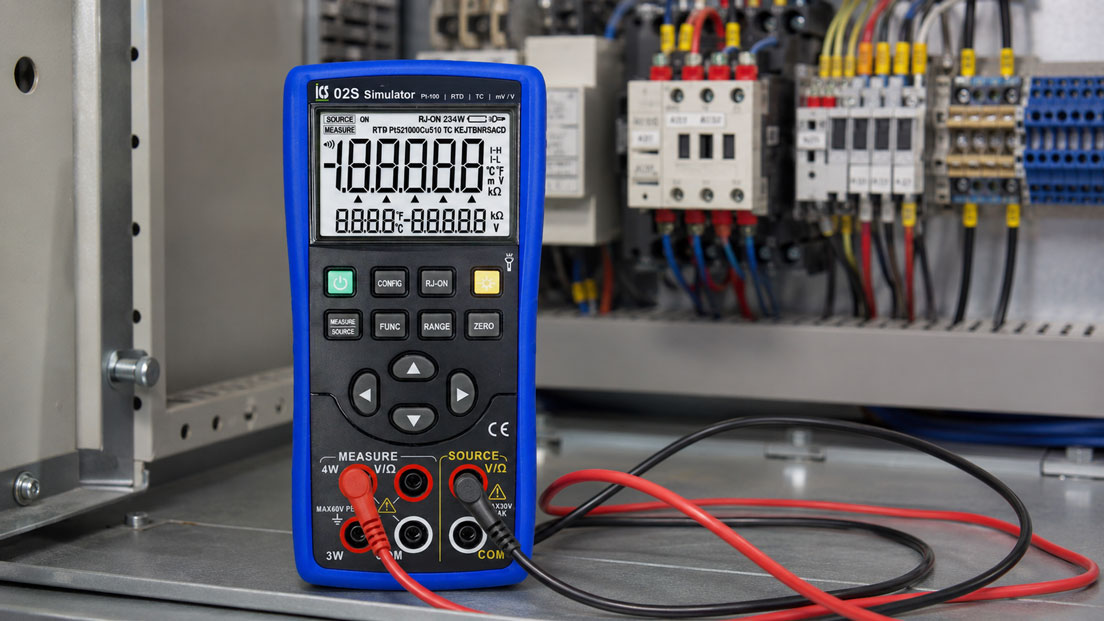
In practice, temperature measuring chains are often only checked when measured values appear implausible, a temperature transmitter does not provide the correct signal or the PLC displays an incorrect value. Often, attempts are then made to actually heat or cool the temperature probe. However, this is not always practical, not reproducible and often unnecessarily time-consuming in control cabinets or with installed sensors.
A Pt100 can also be simulated electrically. No real temperature process is generated; instead, a defined resistance value is provided that corresponds to a specific temperature. This allows targeted testing of whether the transmitter, display, controller or PLC input correctly processes the simulated temperature value.
This article explains how Pt100 simulation works, why 2-, 3- and 4-wire connections must be evaluated differently, how defined temperatures can be simulated and how transmitters, 4–20 mA outputs, limit values, sensor break detection and PLC scaling can be checked effectively.
Table of contents
- Basics: What does simulating Pt100 mean?
- Pt100 resistance values: Understanding temperature as an ohm value
- 2-, 3- and 4-wire connection: Why wiring is decisive
- Testing temperature transmitters: From Pt100 input to output signal
- Testing PLC input and display: Correctly evaluating scaling
- 4–20 mA in temperature measuring chains: Why the UPS4E is important here
- Testing limit values, alarms and sensor break
- Typical errors during Pt100 simulation
- Table: Typical Pt100 resistance values
- Practical example: Testing a temperature transmitter in the control cabinet
- Table: What is checked with which test method?
- Which measuring instruments / products are suitable?
- Conclusion: Pt100 simulation saves time and makes errors visible faster
- FAQ: Frequently asked questions about Pt100 simulation
Basics: What does simulating Pt100 mean?
A Pt100 is a resistance thermometer. The electrical resistance of the sensor changes with temperature. At 0 °C, a Pt100 has a resistance of 100 ohms. As the temperature rises, the resistance also increases. As the temperature falls, the resistance decreases.
When simulating a Pt100, this resistance value is generated artificially. A simulator or process calibrator provides, for example, the resistance corresponding to a temperature of 0 °C, 50 °C or 100 °C. The connected measuring instrument, temperature transmitter or PLC then “sees” a Pt100 with exactly this temperature.
The major advantage lies in reproducibility. Instead of physically placing a probe in a bath, oven or on a heat source, a defined temperature point can be specified directly and electrically. This allows measuring chains to be checked faster, limit values to be tested more specifically and scaling errors to be identified more easily.
It is important that the simulation matches the measuring chain. A Pt100 input must not be confused with a thermocouple signal. 2-, 3- and 4-wire connections must also be connected correctly, otherwise an apparent temperature error can quickly occur even though only the wiring is incorrect.
Pt100 resistance values: Understanding temperature as an ohm value
In a Pt100 measurement, temperature is not transmitted directly; instead, a resistance value is measured. The evaluation device converts this resistance into a temperature using a characteristic curve. For troubleshooting, it is therefore helpful to roughly know which resistance values correspond to which temperatures.
A common test point is 0 °C, because a Pt100 has exactly 100 ohms at this point. Another typical point is 100 °C with approximately 138.51 ohms. If these values are simulated and the measuring instrument displays significantly different temperatures, the cause is often incorrect scaling, the wrong sensor type, line resistances, wiring or an incorrectly parameterized input.
In practice, not every resistance value needs to be known by heart. A good simulator displays the temperature directly in °C and internally generates the correct resistance. Nevertheless, a basic understanding helps to classify measurement errors more easily. For example, if an additional line resistance of a few ohms is not compensated in a 2-wire measurement, this can already result in a significant temperature error.
Especially in maintenance, simulating defined points is often faster than performing a full temperature calibration. It answers the question: Does the measuring chain respond plausibly and correctly to a known Pt100 value?
2-, 3- and 4-wire connection: Why wiring is decisive
Pt100 probes can be designed as 2-, 3- or 4-wire connections. This connection type influences how line resistances are taken into account in the measurement. This is exactly where many errors occur in practice.
With a 2-wire connection, the line resistance is added directly to the sensor resistance. With longer cables, this can lead to a temperature value that is too high. This connection type is simple, but only suitable to a limited extent for accurate measurements.
With a 3-wire connection, the line resistance is partially compensated by the evaluation electronics. The prerequisite is that the cables are similar in design and correctly connected. The 3-wire connection is very common in industry because it combines accuracy and wiring effort well.
With a 4-wire connection, the line resistance is compensated most effectively. The current and voltage paths are separated, which keeps the influence of the cable very small. This connection type is often used for more accurate measurements, test benches, laboratory applications or reference measurements.
When simulating, the connection type of the input must be taken into account. A 3-wire input should not be connected like a 2-wire input. A 4-wire input expects different wiring than a simple resistance input. Incorrect connection can lead to implausible values or error messages.
Testing temperature transmitters: From Pt100 input to output signal
A temperature transmitter converts the Pt100 resistance into a standardized output signal. In many systems, this is a 4–20 mA signal, a 0–10 V signal or a digital signal. The transmitter therefore forms the interface between sensor and control system.
During testing, the Pt100 at the transmitter input is replaced by a simulator. A defined temperature value is then specified. The transmitter must then provide the corresponding signal at the output. For example, if the measuring range is scaled to 0…100 °C, 0 °C should correspond to the lower output value and 100 °C to the upper output value.
This test is particularly helpful when it is unclear whether the error comes from the sensor, the transmitter or the downstream PLC. If a correct Pt100 value is simulated at the input and the output reacts incorrectly, the fault is more likely to be in the transmitter or its parameterization. If the transmitter reacts correctly but the PLC displays an incorrect value, the cause is more likely to be wiring, input card or scaling.
Before working in the control cabinet, the system must be assessed safely. Tests on electrical systems and controls may only be carried out by qualified personnel. It should also be clear whether the sensor may be disconnected during the running process or whether this affects alarms, shutdowns or process releases.
Testing PLC input and display: Correctly evaluating scaling
Many temperature errors do not originate from the Pt100 itself, but from the scaling of the PLC or display. A transmitter can correctly output 4–20 mA, while the PLC converts the current value to the wrong temperature range.
A typical issue is confusion of the measuring range. For example, the transmitter is set to 0…150 °C, but the PLC calculates with 0…100 °C. In that case, the beginning and end may appear partially correct, but the displayed values are wrong across the range.
Units and limit values can also be incorrectly parameterized. A display may show °C, while internally the controller uses a different scaling. Alarm limits may also be intended correctly, but refer to incorrect raw values.
A good test therefore includes several points within the measuring range. Checking only 0 °C or only room temperature is often not sufficient. At least one lower point, one middle point and one upper point are useful. This makes it visible whether offset, span and linearity of the scaling are plausible.
4–20 mA in temperature measuring chains: Why the UPS4E is important here
Many Pt100 measuring chains do not end directly at a Pt100 input, but at a temperature transmitter with a 4–20 mA output. In this case, the measuring chain should be divided into two parts: Pt100 simulation at the input and current signal testing at the output.
A suitable Pt100 simulator or process calibrator is used for the Pt100 side. This checks whether the transmitter reacts correctly to defined temperature values. For the 4–20 mA side, a current loop calibrator is useful. This makes it possible to check whether the output signal arrives correctly, whether the cable is in order and whether the PLC correctly scales the current value.
The UPS4E current loop calibrator / loop calibrator is suitable for such tasks. It can measure and simulate mA signals and is therefore particularly helpful when a temperature transmitter with a 4–20 mA output is to be commissioned or tested.
A practical procedure is as follows: First, a Pt100 value is simulated at the transmitter input. Then the mA signal is measured at the output. In addition, an mA value can then be simulated at the PLC to test the input card and scaling independently of the transmitter. This allows the cause of the error to be narrowed down much faster.
Testing limit values, alarms and sensor break
Pt100 simulation is not only suitable for testing normal measured values, but also for limit values and fault states. In many systems, temperature limits are stored that trigger an alarm, shutdown, fan release, heating control or process lockout.
With a simulator, such limit values can be approached specifically. Instead of heating the real process, for example, a temperature just below and just above the switching point is simulated. This makes it possible to check whether the system reacts correctly and whether hysteresis, delay time and alarm message match the process requirement.
Sensor break or line faults can also be evaluated, provided that the test instrument or measuring chain supports the corresponding states. Many transmitters detect open circuits, short circuits or implausible resistances and then output defined fault behavior. This behavior should be known so that the PLC does not confuse a fault with a real temperature value.
Special care must be taken with safety-relevant functions. Simulating a limit value can trigger real switching actions. It should therefore be clear before the test whether outputs, actuators, heaters, pumps or safety functions are affected.
Typical errors during Pt100 simulation
A common error is the wrong connection type. If a 3-wire input is not correctly bridged or a 4-wire input is connected like a 2-wire input, implausible values occur. The error is then often incorrectly attributed to the transmitter.
Another error is the wrong sensor characteristic. Some inputs can process Pt100, Pt1000, Ni100, thermocouples or other sensor types. If the input is parameterized to the wrong sensor type, the simulated value will not match the display.
The scaling of the output signal is also often overlooked. A transmitter can measure correctly but be set to a different temperature range than the PLC. The result is systematically incorrect values, even though the sensor and transmitter basically work.
Finally, the cable route must not be forgotten. If the simulator is connected directly to the transmitter, the field cable to the actual sensor is not checked. If, on the other hand, simulation is performed at the field end, cable, terminals and transitions are included. Which variant is useful depends on which source of error is to be narrowed down.
Table: Typical Pt100 resistance values
The following table shows typical approximate values for a Pt100 according to a common characteristic curve. For accurate calibration tasks, a suitable calibrator, corresponding table or device characteristic curve should always be used.
| Temperature | Approximate Pt100 resistance | Typical use during testing |
|---|---|---|
| -50 °C | approx. 80.31 Ω | Testing the lower measuring range in cooling or outdoor applications |
| 0 °C | 100.00 Ω | Reference point and quick plausibility check |
| 25 °C | approx. 109.73 Ω | Testing in the room temperature range |
| 50 °C | approx. 119.40 Ω | Testing typical process or control cabinet temperatures |
| 100 °C | approx. 138.51 Ω | Testing the upper range of many standard measuring chains |
| 150 °C | approx. 157.33 Ω | Testing extended measuring ranges |
Practical example: Testing a temperature transmitter in the control cabinet
In a system, the PLC permanently displays a temperature that is too high for a Pt100 measuring circuit. The process itself is stable, and the real probe has already been visually checked. It is unclear whether the fault lies with the sensor, the cable, the temperature transmitter or the PLC scaling.
The technician separates the measuring chain in a controlled manner and first simulates defined Pt100 values directly at the input of the temperature transmitter. At 0 °C, 50 °C and 100 °C, the transmitter reacts plausibly. The 4–20 mA output signal is then measured with a current loop calibrator. This signal also matches the set temperature range.
In the next step, the PLC side is checked. A defined mA value is simulated there. This shows that the PLC scaling is set to a different temperature range than the transmitter. The fault is therefore not in the Pt100 and not in the transmitter, but in the parameterization of the input card or visualization.
The example shows why the combination of Pt100 simulation and 4–20 mA testing is so effective. The measuring chain is divided into individual sections. This makes it possible to find the cause of the error faster without having to change the real temperature process.
Table: What is checked with which test method?
| Test | What is checked? | What is not automatically checked? |
|---|---|---|
| Pt100 simulation directly at the transmitter | Pt100 input, transmitter parameterization, basic function | Field cable and real sensor |
| Pt100 simulation at the field end | Cable, terminals, transmitter and input circuitry | The real sensor itself |
| mA measurement at the transmitter output | Output signal of the temperature transmitter | PLC scaling and display |
| mA simulation at the PLC input | PLC input, scaling, visualization and limit values | Transmitter and Pt100 input |
| Limit value simulation | Alarm limits, hysteresis, delay and message behavior | Real thermal behavior of the process |
Which measuring instruments / products are suitable?
Simulators are suitable for simulating Pt100 and other temperature signals when defined resistance, RTD, thermocouple or voltage signals need to be generated. This allows temperature transmitters, displays, controllers and PLC inputs to be checked much faster than with a real temperature process.
A suitable device for such tasks is the ICS 02S simulator for Pt-100 | RTD | TC | mV/V. It is suitable for users who want to simulate and measure Pt100 or RTD signals and also need to test typical temperature and voltage signals.
For more extensive testing and calibration tasks, process calibrators / electrical calibrators are also relevant. They are used when several signal types, transmitters, process signals or complete measuring chains need to be checked.
If the temperature measuring chain works via a transmitter with a 4–20 mA output, the UPS4E current loop calibrator / loop calibrator should also be considered. It is the right tool for measuring and simulating mA signals and checking the current loop up to the PLC or display.
In practice, the combination of Pt100 simulator and current loop calibrator is often the most efficient solution: The Pt100 simulator checks the sensor input side, while the UPS4E checks the 4–20 mA side. This shows whether the error lies in the sensor replacement signal, transmitter, wiring or PLC scaling.
Conclusion: Pt100 simulation saves time and makes errors visible faster
Pt100 simulation is a very practical method for checking temperature measuring chains without having to generate a real temperature process. Instead of heating or cooling a sensor, a defined resistance value is specified. This allows transmitters, displays, controllers and PLC inputs to be checked quickly and reproducibly.
The decisive factor is to divide the measuring chain correctly. The Pt100 side checks resistance value, connection type and transmitter input. The output side checks 4–20 mA, 0–10 V or other process signals. Only when both sides are evaluated cleanly can an error be narrowed down reliably.
Especially in maintenance, control cabinet construction, commissioning and troubleshooting, Pt100 simulation saves a great deal of time. It does not replace every temperature calibration in the real process, but it provides a very fast and meaningful check of the electrical measuring chain.
FAQ: Frequently asked questions about Pt100 simulation
What does simulating Pt100 mean?
Simulating Pt100 means providing a defined resistance value that corresponds to a specific temperature. The connected measuring instrument or transmitter evaluates this resistance as if a real Pt100 probe were connected.
Why should a Pt100 be simulated instead of heating the probe?
Simulation is faster, more reproducible and often possible directly in the control cabinet. It is particularly suitable for checking transmitters, displays, controllers or PLC scaling without having to change the real process.
Can the real probe be tested with Pt100 simulation?
Not directly. The simulation electrically replaces the probe. It tests the downstream measuring chain. To test the real probe, it must be measured, compared or checked at a suitable temperature point or in a calibration bath.
Where should the simulator be connected?
That depends on the troubleshooting task. Directly at the transmitter, the input is checked. At the field end, cable, terminals and transitions are also included. In unclear cases, both variants can be useful.
What must be considered with 2-wire Pt100?
With a 2-wire connection, the line resistance is added to the sensor value. With longer cables, this can result in a temperature value that is too high. For accurate measurements, 2-wire technology is therefore only suitable to a limited extent.
Why is 3-wire technology so common in industry?
3-wire technology reduces the influence of line resistance, but requires less wiring effort than 4-wire technology. The prerequisite is correct and preferably symmetrical wiring.
When is 4-wire technology useful?
4-wire technology is useful when high accuracy is required or line resistances need to be compensated as reliably as possible. It is often used for reference measurements, laboratory applications or more precise measuring chains.
Why does the transmitter display incorrectly despite a simulated Pt100 value?
Possible causes include incorrect connection type, wrong sensor type, wrong characteristic curve, incorrect parameterization, a defective input or unsuitable simulator connection. Therefore, the wiring diagram and input settings should always be checked.
How do you test a temperature transmitter with a 4–20 mA output?
First, a Pt100 value is simulated at the input. Then the mA signal is measured at the output. With the UPS4E, an mA signal can additionally be simulated to test the PLC input and scaling independently of the transmitter.
Which points should be checked in PLC scaling?
Important points include the set temperature range, the assignment of 4 mA and 20 mA, unit, offset, span, limit values and visualization. Testing with at least three points is useful: lower, middle and upper range.
Can sensor break be tested with a simulator?
Depending on the transmitter and test instrument, a fault state such as open circuit or short circuit can be simulated or tested by deliberately disconnecting the measuring line. It must be clear which reaction the system will trigger.
Why is a single test point often not enough?
A single point only shows whether the measuring chain responds plausibly at that point. Scaling errors, incorrect span or swapped end values are easier to detect with several points across the measuring range.
Is Pt100 simulation the same as calibration?
No. Simulation tests the electrical measuring chain with defined signals. A full calibration additionally evaluates the measurement deviation under defined conditions and with traceable references.
What is the difference between Pt100 and thermocouple simulation?
A Pt100 is simulated using resistance. A thermocouple is simulated using a very small voltage in the mV range and additionally requires the correct thermocouple characteristic curve as well as suitable cold junction compensation.
Which device is suitable for Pt100 simulation?
A simulator or process calibrator that can generate RTD or Pt100 signals is suitable for Pt100 simulation. For measuring chains with a 4–20 mA output, an additional current loop calibrator such as the UPS4E is useful.