


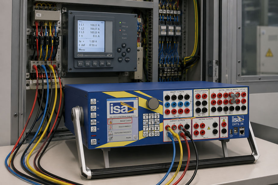
An overcurrent protection relay is to be tested as part of commissioning or a periodic inspection. For example, the relay is set to a pickup value of 1.20 A and a defined trip characteristic.
The current is slowly increased using a relay test set.
The relay picks up at 1.24 A.
A higher test current is then injected and the trip time is measured. However, the result differs significantly from the expected value.
Is the protection relay faulty?
Not necessarily.
During protection relay testing, even small differences in the test setup can significantly influence the result.
Typical causes include:
- incorrect current or voltage channels,
- swapped phases,
- incorrect phase angles,
- unsuitable ramp speed,
- incorrect starting point for the time measurement,
- incorrect binary contact used as the stop signal,
- NO and NC contacts confused,
- protection functions not reset,
- incorrect CT or VT ratios in the test plan,
- incorrect characteristic parameters.
Secondary injection therefore involves more than simply applying a test current.
A defined measurement chain is essential:
Test plan → current/voltage outputs → protection relay → protection logic → output contact → binary input of the test set → time measurement → evaluation
Test equipment for these applications can be found at ICS Schneider under Test Equipment for Power Systems. An overview of additional electrical measuring and test equipment can be found under Electrical Measuring and Test Equipment.
Table of Contents
- What does secondary injection mean when testing protection relays?
- Distinguishing between primary and secondary testing
- Safe isolation before relay testing
- Create a test plan before injection
- Correctly assign current and voltage channels
- Consider phase angle and phase sequence
- Determine the pickup value of the protection relay
- Use ramp testing correctly
- Use step testing for trip times
- Measure trip time correctly
- Systematically test the trip characteristic
- Test overcurrent protection
- Test directional protection functions
- Correctly assign binary inputs and outputs
- Dropout value and reset between tests
- Evaluate target value, actual value and tolerance
- Distinguish IEC 61850 signals from conventional contacts
- Typical fault patterns
- Systematic procedure
- Practical example: overcurrent protection appears too slow
- Document the test report completely
- Suitable ICS products
- Conclusion
- FAQ
What does secondary injection mean when testing protection relays?
During a secondary test, defined electrical test quantities are injected directly into the inputs of the protection relay or into its test circuit.
The test set thereby simulates the signals that the relay would receive during actual operation, for example from:
- current transformers,
- voltage transformers,
- sensors,
- or digital process interfaces.
Typical test quantities include:
- AC current,
- AC voltage,
- frequency,
- phase angle,
- phase sequence,
- balanced and unbalanced conditions.
The relay processes these signals according to its configuration.
At the same time, the test set monitors when, for example, a trip contact or another output signal changes state.
This makes it possible to test, among other things:
- pickup values,
- dropout values,
- trip times,
- characteristic curves,
- directional functions,
- logic functions.
Distinguishing between primary and secondary testing
Primary and secondary testing examine different parts of the protection chain.
| Test method | Scope of test | Typical purpose |
|---|---|---|
| Secondary injection | Direct testing of protection relay inputs and protection functions | Configuration, characteristic curve, trip time, logic |
| Primary injection | Testing through the actual primary circuit | Complete chain including current transformer and wiring |
A successful secondary test therefore does not automatically confirm the complete measurement chain from the primary conductor to the relay.
For example:
- incorrect current transformer ratios,
- wiring errors,
- incorrect polarity,
- problems at test terminal blocks
may be located outside the directly tested relay circuit.
Conversely, secondary injection offers a major advantage:
The protection relay can be tested using precisely defined currents, voltages, angles and time sequences without having to generate the corresponding primary quantities in the power circuit.
Safe isolation before relay testing
Protection relay tests are performed on electrical power systems. Before starting, it must therefore be clearly defined which current, voltage, auxiliary supply and trip circuits are to remain energized or isolated during the test.
The specific procedure depends on the installation, switching authorization, test terminal system and company work instructions and must only be performed by appropriately qualified personnel.
Pay particular attention to current transformer circuits
The secondary circuit of a current transformer must not be opened in an uncontrolled manner while the CT is carrying primary current.
During secondary injection, suitable test terminal blocks or test plugs must therefore ensure that:
- the actual current transformer circuit is handled correctly,
- the relay side is positively isolated from the transformer circuit,
- an open CT secondary circuit cannot create a hazardous condition.
Isolate voltage transformer circuits
In voltage circuits, it must be prevented that voltage generated by the test set is back-fed into an energized system circuit.
The corresponding test or isolation points must therefore be clearly defined.
Handle the trip circuit deliberately
Before the test, it must also be clarified:
Is only the relay to be tested, or should the actual circuit breaker also trip?
During a pure relay test, actual breaker tripping is frequently blocked or isolated in a controlled manner.
During an end-to-end or complete functional test, actual breaker operation may instead be part of the test objective.
This distinction must be defined before the first test point.
Create a test plan before injection
A protection test should not begin by injecting arbitrary currents and observing the relay response.
The protection settings should first be recorded.
For a simple overcurrent protection function, for example:
- current transformer ratio,
- relay rated current,
- pickup value I>,
- second stage I>>, where applicable,
- characteristic type,
- time multiplier or time factor,
- directional or non-directional,
- trip contact,
- any blocking conditions.
Do not confuse primary and secondary values
A protection relay may display its settings as primary values while the test set generates secondary current.
For a current transformer:
600 A / 1 A
the following applies:
600 A primary = 1 A secondary
A primary protection setting of:
I> = 720 A
therefore corresponds to the following secondary value:
I> = 720 / 600 · 1 A = 1.20 A
If this relationship is not taken into account correctly, a perfectly functioning relay may appear to have an incorrect pickup value.
Correctly assign current and voltage channels
With multi-phase protection relays, it must be clearly documented which output of the test set is connected to which relay channel.
For example:
| Test set | Relay |
|---|---|
| I1 | IL1 |
| I2 | IL2 |
| I3 | IL3 |
| V1 | UL1 |
| V2 | UL2 |
| V3 | UL3 |
With simple non-directional overcurrent functions, a channel error may be noticed quickly.
With:
- directional protection,
- distance protection,
- differential protection,
- active or reactive power protection
an incorrect phase assignment can produce results that are much more difficult to interpret.
Consider phase angle and phase sequence
For a three-phase test, it is not sufficient to inject three currents with the same magnitude.
Their phase angles must also be correct.
A typical positive phase sequence can, for example, be described as:
IL1 = I ∠ 0°
IL2 = I ∠ -120°
IL3 = I ∠ +120°
An equivalent representation using different angular references is possible.
The important point is that the angle definitions in:
- the test software,
- the relay configuration,
- the wiring diagram
are interpreted consistently.
Polarity errors can reverse the direction
If, for example, a current channel is connected with reversed polarity, this corresponds electrically to a phase shift of 180°.
With non-directional overcurrent protection, the magnitude may still appear plausible.
With a directional function, however, the same error can result in:
forward faults being detected as reverse faults or the protection function not being enabled at all.
Determine the pickup value of the protection relay
The pickup value is frequently determined using a ramp test.
For overcurrent protection, the test current can initially be set below the threshold, for example:
I = 0.90 · I>
The current is then increased in a controlled manner.
As soon as the relay picks up the relevant protection stage, the corresponding current value is stored.
Example
Setting:
I> = 1.20 A
Measured pickup value:
Ipickup = 1.22 A
Relative deviation:
δ = (1.22 - 1.20) / 1.20 · 100 %
δ ≈ +1.7 %
Whether this value is permissible depends on the relay, protection function, manufacturer specification and agreed test tolerance.
Use ramp testing correctly
A ramp test is particularly suitable for determining:
- pickup values,
- dropout values,
- boundaries of a directional zone,
- frequency thresholds,
- voltage thresholds.
The test quantity is changed continuously or in steps.
Ramp speed influences the result
A very fast ramp can skip over a threshold region.
An extremely slow ramp, on the other hand, may cause time-dependent functions to operate during the ramp itself.
The following must therefore be matched to the protection function being tested:
- starting value,
- end value,
- step size or ramp speed,
- dwell time.
Do not use a ramp test for every time measurement
A common mistake is attempting to determine the trip time at the same time as using a current ramp.
This is problematic because it is not clearly defined at what point the protection function actually saw the specified fault current.
For reproducible trip-time measurements, a defined step test is therefore normally more suitable.
Use step testing for trip times
During a step test, a defined pre-fault condition is first established.
For example:
I = 0 A
or:
I = 0.8 · I>
At an exactly defined time, the current is then stepped to:
I = 2 · I>
The time measurement starts simultaneously.
When the selected trip contact changes state, the timer stops.
This gives:
tmeasured = ttrip contact - tfault start
This method represents the timing sequence much more clearly than a slow ramp.
Measure trip time correctly
Before measuring the time, it must be clearly defined which signals are used to start and stop the timer.
Start
Typical starting point:
start of the defined fault condition
for example, the current step to 2 × I>.
Stop
The following can, for example, be used as a stop signal:
- relay trip contact,
- pickup contact,
- separate protection-function contact,
- digital trip signal.
These signals do not necessarily occur at the same time.
Do not confuse the trip contact with the circuit breaker contact
If the relay output is evaluated directly, the measured time essentially includes the protection processing time and output response of the relay.
If, on the other hand, an auxiliary contact of the actual circuit breaker is used as the stop signal, the result additionally includes the breaker operating time.
In simplified form:
Total time ≈ relay trip time + transmission time + circuit breaker operating time
Both measurements can be useful.
However, they answer different questions.
Systematically test the trip characteristic
For time-dependent overcurrent functions, a single test point is often not sufficient.
Instead, several multiples of current are tested.
The following can be defined:
M = Itest / I>
Typical test points can, for example, be:
- 1.2 × I>,
- 1.5 × I>,
- 2 × I>,
- 5 × I>,
- 10 × I>.
The appropriate points depend on the characteristic curve, protection concept and manufacturer specifications.
Definite-time characteristic
With a definite-time stage, the set delay time remains essentially constant over a defined current range.
Example:
I> = 1.20 A
t> = 0.50 s
At a sufficiently high overcurrent, the relay should then trip approximately according to the configured time delay.
Inverse characteristic
With an inverse characteristic, the trip time decreases as the overcurrent increases.
In simplified terms, many characteristics follow a mathematical relationship of the form:
t = f(I / I>, characteristic type, time factor)
The following must therefore be transferred correctly from the relay configuration during testing:
- characteristic type,
- pickup value,
- time multiplier or TMS/TD,
- test current.
Confusing the characteristic family can produce much larger timing deviations than the actual measurement tolerance of the relay.
Test overcurrent protection
A typical test plan for a simple overcurrent protection function can include several tests.
1. Pickup value
Slowly increase the current from a safe non-pickup region towards I>.
Result:
Ipickup
2. Dropout value
After pickup has occurred, slowly reduce the current.
Result:
Idropout
3. Trip time
Apply a defined step, for example to:
2 × I>
and measure the time until the trip contact operates.
4. Additional characteristic points
Depending on the protection function, additional current multiples are tested.
5. Second protection stage
If, for example:
I>>
is also configured, it is tested separately.
It must be ensured that another protection stage does not unintentionally determine the result.
Test directional protection functions
With directional protection functions, the magnitude of current and voltage is not the only decisive factor.
The relay also evaluates the phase relationship between the quantities used.
For directional overcurrent protection, for example, the following may be relevant:
- current magnitude,
- voltage magnitude,
- angle between current and reference voltage,
- phase sequence,
- polarity of the measurement channels,
- configured directional zone.
Typical error
The relay is intended to trip in the forward direction.
The test current has the correct magnitude.
The test voltage also has the correct magnitude.
However, the current angle is incorrectly set by 180°.
The relay therefore interprets the test case as a reverse fault.
Result:
no trip
The initial assumption may be:
directional protection faulty
In reality, the problem is simply an incorrect phase relationship in the test setup.
Test the directional boundary
During an angle test, the phase angle can be varied deliberately.
This makes it possible to determine the angular range in which the protection function:
- enables,
- blocks,
- or changes its directional decision.
Such tests are particularly sensitive to incorrect phase references and reversed polarity.
Correctly assign binary inputs and outputs
Correct assignment of the binary signals is essential for time measurement.
Relay output to the test set
Typical setup:
Trip contact of protection relay → binary input of relay test set
The test set detects the state change and stops the time measurement.
Before testing, the following must be clarified:
- which output actually belongs to the protection stage,
- whether it is an NO or NC contact,
- whether the contact is evaluated as a potential-free or energized signal,
- which state is defined as “trip”.
Do not confuse NO and NC
A relay contact may, for example, be open in its normal state:
NO = Normally Open
and close on trip.
Another output may operate in exactly the opposite way:
NC = Normally Closed
and open on trip.
If the test software is configured for the wrong transition, the timer may:
- not stop at all,
- stop before the test starts,
- or determine an apparently incorrect trip time.
Binary outputs of the test set
For more complex tests, states often also have to be simulated to the relay.
For example:
- circuit breaker open,
- circuit breaker closed,
- enable active,
- blocking active,
- external interlock,
- automatic mode.
If the test system being used provides corresponding binary outputs, these signals can be integrated into the test sequence.
Here too, the signal type, voltage and permissible input circuit of the protection relay must be considered.
Dropout value and reset between tests
Between two tests, it must be ensured that the protection function has returned to a defined initial state.
This is particularly important with:
- latched trip outputs,
- thermal protection models,
- memory functions,
- autoreclosing logic,
- multi-stage protection functions.
If the next test point is started immediately after a trip, internal relay states may still be active.
The result may therefore differ from the first test.
Dropout ratio
For certain functions, the ratio between dropout and pickup value can also be evaluated:
kr = Idropout / Ipickup
This indicates how far the measured quantity must decrease following pickup before the protection function drops out again.
Evaluate target value, actual value and tolerance
A relay test report should not consist solely of:
PASSED
or:
FAILED
A useful presentation includes:
| Test point | Target | Actual | Deviation | Tolerance | Evaluation |
|---|---|---|---|---|---|
| I> pickup value | 1.20 A | 1.22 A | +1.7 % | according to specification | Passed/Failed |
| Trip time at 2 × I> | 0.50 s | 0.508 s | +8 ms | according to specification | Passed/Failed |
The permissible tolerance must not simply be derived arbitrarily from the accuracy of the test set.
The following must be considered in particular:
- manufacturer specifications for the protection relay,
- functional standard,
- project requirements,
- grid operator requirements,
- company test procedure,
- measurement uncertainty of the test set.
Distinguish IEC 61850 signals from conventional contacts
In conventional protection systems, the trip is frequently evaluated via a physical relay contact.
In digital substation architectures, however, protection information can be transmitted via IEC 61850.
Depending on the system, this may include, for example:
- GOOSE messages,
- Sampled Values,
- digital substation signals
as part of the protection test.
This also changes the measurement chain.
Instead of:
relay contact → binary input
a digital trip event may, for example, be evaluated.
The test objective must therefore clearly define whether the test covers:
- only the analog protection function,
- the protection function including communication,
- or the complete end-to-end chain.
Typical fault patterns when performing secondary protection relay tests
| Observation | Possible cause | Recommended check |
|---|---|---|
| Pickup current significantly incorrect | Primary/secondary value confused | Check CT ratio and relay display |
| Only one phase responds incorrectly | Channel assignment or wiring | Check I1/I2/I3 individually |
| Three-phase function behaves unexpectedly | Incorrect phase sequence | Check angles and phase sequence |
| Directional protection does not trip | Incorrect current/voltage angle | Check phasor diagram of the test case |
| Direction exactly reversed | Polarity of one channel reversed | Check connection and angular reference |
| Pickup value depends strongly on ramp speed | Unsuitable ramp | Adjust step size and dwell time |
| Trip time differs between repeated tests | Relay not fully reset | Check reset and pre-fault condition |
| Timer does not stop at all | Incorrect binary contact | Check trip contact and binary input |
| Timer stops immediately | Incorrect NO/NC logic or initial state | Check contact logic |
| Measured time significantly longer than relay operating time | Circuit breaker contact used as stop signal | Check measurement point and test objective |
| Inverse characteristic matches at only one point | Incorrect characteristic type or time factor | Compare relay settings with test plan |
| Second overcurrent stage affects timing measurement | Test current activates several stages | Check active protection functions and time stages |
| Relay does not respond to test current at all | Test circuit not correctly connected to relay side | Check test plug, isolation points and current path |
| System indication remains active after the test | Test mode, blocking or trip latch not reset | Perform return-to-service check |
Systematic procedure for protection relay testing
The following procedure is recommended for reproducible tests:
- Define the test objective: Individual protection function, complete relay function or end-to-end test?
- Identify the protection relay: Document type, serial number, firmware and installation location.
- Save the settings: Document the current protection settings before testing.
- Record instrument transformer data: Check CT and VT ratios.
- Define the switching state: Clarify test authorization, work authorization and system condition.
- Handle CT circuits safely: Use the designated test and short-circuiting facilities.
- Isolate VT circuits: Prevent back-feeding of test voltage.
- Define the trip circuit: Block actual breaker operation or intentionally include it in the test plan.
- Assign test channels: Clearly document I1/I2/I3 and V1/V2/V3.
- Assign binary signals: Define start, pickup and trip contacts.
- Check phase relationships: Verify angles and phase sequence before the first dynamic test.
- Test the pickup value: Use a suitable ramp or step sequence.
- Test the dropout value: Where relevant to the protection function.
- Test the trip time: Use a defined step test.
- Test the characteristic: Use several representative test points.
- Test additional protection stages: Evaluate I>>, I>>> or other functions separately.
- Test the directional function: Deliberately vary current/voltage angles.
- Test the logic: Include enables, blocking and binary inputs where required.
- Reset between tests: Restore a defined initial state.
- Evaluate the results: Document target, actual value, deviation and permissible tolerance.
- Generate the test report: Store test parameters and results completely.
- Remove the test setup: Remove test leads and test plugs in a controlled manner.
- Restore the system: Return trip circuit, CT/VT circuits and protection functions to their intended operating state.
- Final check: Verify that no test blocking or temporary configuration remains active.
Practical example: overcurrent protection appears too slow during testing
A three-phase protection relay has the following simplified setting:
I> = 1.00 A
For a particular test point, an expected trip time of:
t = 0.50 s
is assumed.
Step 1: first test attempt
The tester starts at:
0.80 A
and slowly increases the current to:
2.00 A
The relay trips during the ramp.
The test software shows:
0.82 s
The initial conclusion is:
Relay 320 ms too slow
Step 2: analyze the test method
On closer examination, it becomes clear that the timer was started at the beginning of the current ramp.
However, the relay only received the defined test current for the intended characteristic point later in the ramp.
The measured time therefore additionally included part of the ramp time.
Step 3: test the pickup value separately
The pickup value is first determined using a suitable ramp.
Result:
Ipickup = 1.01 A
The pickup threshold is therefore plausible in this example.
Step 4: test the trip time separately
For the time measurement, a defined pre-fault condition is first established.
A direct step is then applied to:
I = 2.00 A
The timer starts exactly at this step.
The correct trip contact is used as the stop signal.
Step 5: result
The measured value is:
t = 0.506 s
The result is therefore only:
6 ms
above the assumed target value of 0.500 s.
Result
The protection relay was not too slow.
The originally measured deviation was caused by an unsuitable test method.
The ramp test was appropriate for determining the pickup value, but not for the defined measurement of the trip time.
Document the test report completely
A good relay test report should remain understandable later even without detailed knowledge of the original test setup.
Useful information includes, for example:
- system designation,
- bay designation,
- protection relay manufacturer and type,
- serial number,
- firmware version,
- settings set or file version,
- CT ratio,
- VT ratio,
- test set,
- serial number of the test set,
- calibration status of the test set,
- date,
- tester,
- current and voltage channel assignment,
- phase angles used,
- binary contact assignment,
- pickup values,
- dropout values,
- trip times,
- characteristic points,
- target values,
- actual values,
- tolerances,
- Passed/Failed,
- remarks and deviations.
For tests performed after parameter changes, it should also be clearly documented which settings set was active:
before the test → during the test → after completion
in the device.
Suitable ICS products for protection relay testing
DRTS 34 – automatic three-phase relay test set
The DRTS 34 available from ICS is particularly suitable for modern protection relay testing.
The system simultaneously provides:
- 3 current generators,
- 4 voltage generators,
- 1 battery simulator output.
The current outputs provide:
3 × 32 A
or, when connected together:
1 × 96 A
with high available output power.
Other relevant features include:
- output accuracy better than 0.05%,
- manual operation via color display,
- USB and Ethernet interfaces,
- IEC 61850 interface,
- GPS and IRIG-B interface for end-to-end applications,
- connection to TDMS.
The DRTS 34 is therefore suitable, for example, for:
- overcurrent protection,
- voltage protection,
- frequency protection,
- directional protection,
- distance protection,
- three-phase multifunction protection relays.
Further information can be found under DRTS 34 at ICS Schneider.
DRTS 66 – six current and six voltage generators
For protection tests requiring a larger number of analog quantities simultaneously, ICS offers the DRTS 66.
The instrument provides:
- 6 current generators,
- 6 voltage generators,
- 1 battery simulator output.
Depending on the connection arrangement, the current outputs provide, among other configurations:
6 × 32 A
3 × 64 A
or:
1 × 128 A
.
The larger number of simultaneous output channels makes the system particularly useful for more complex multi-phase protection functions in which several current or voltage systems must be simulated at the same time.
The DRTS 66 also supports IEC 61850 and TDMS software.
Further information can be found under DRTS 66 at ICS Schneider.
T 1000 PLUS – Secondary Injection Relay Test Set
The T 1000 PLUS is a relay test set specifically designed for secondary injection and is particularly suitable for conventional relay and transformer testing.
Available test functions include:
- current output up to 250 A,
- AC voltage output up to 250 V,
- DC voltage output up to 300 V,
- frequency generator from 15 to 550 Hz,
- phase-angle adjustment,
- battery simulator from 20 to 260 V DC,
- oscilloscope function for current and voltage,
- storage of test results and settings.
The system is therefore suitable, among other applications, for distribution-network relays, single-phase protection relays and relays with a higher burden.
Further information can be found under T 1000 PLUS at ICS Schneider.
TDMS Pro – structure test sequences and protection relay reports
For DRTS test systems, ICS offers TDMS Pro Software for Protective Relay Testing.
The software supports, among other things:
- automatic import of relay settings,
- relay libraries from different manufacturers,
- configuration of DRTS test sets,
- creation of complex test sequences using the Test Plan Editor,
- IEC 61850 tests,
- creation of professional test reports.
TDMS Pro is compatible with, among others:
- DRTS 66,
- DRTS 64,
- DRTS 34,
- DRTS 33.
Especially for periodic protection testing, a saved test plan enables significantly more reproducible execution than a completely manual individual test.
Further information can be found under TDMS Pro at ICS Schneider.
Which solution is suitable for which test task?
| Test task | Recommended solution |
|---|---|
| Three-phase multifunction protection relay | DRTS 34 |
| Overcurrent, voltage and directional protection | DRTS 34 |
| Complex tests with many simultaneous current/voltage channels | DRTS 66 |
| Multi-system or demanding differential protection testing | DRTS 66 |
| Conventional secondary injection and single-phase relay testing | T 1000 PLUS |
| Automated test plans and periodic protection testing | DRTS series with TDMS Pro |
| IEC 61850-based protection testing | DRTS 34 or DRTS 66 with suitable software configuration |
| Automatic test reports and results management | TDMS Pro |
Further systems can be found under Test Equipment for Power Systems at ICS Schneider.
Conclusion
Secondary injection is one of the most important methods for functional testing of modern protection relays.
Defined currents, voltages, frequencies and phase angles are applied directly to the protection relay inputs and the response behavior is measured.
However, the accuracy of the relay test set alone is not sufficient for a reliable test.
Equally important are:
- correct instrument transformer data,
- correct current and voltage channels,
- correct phase sequence,
- correct phase angles,
- suitable ramp and step test methods,
- clearly assigned binary contacts,
- a defined initial state before every test point,
- correctly selected characteristic and time parameters.
A ramp or step test is frequently suitable for determining the pickup value.
For the trip time, however, a defined fault condition should preferably be applied as a step so that the starting point of the time measurement is unambiguous.
With directional functions, the phase relationship between current and voltage additionally becomes critical.
A current channel reversed by 180° can effectively turn a forward fault into a reverse fault from the relay’s perspective.
The binary contact must also be clearly defined.
A relay trip contact, a pickup contact and a circuit breaker auxiliary contact provide different timing information.
Safe isolation of the test circuit from the actual installation is also particularly important.
Current transformer, voltage transformer and trip circuits must be handled in a controlled manner according to the system and work instructions.
After completing the test, complete restoration of all test and blocking states is therefore also part of the test process.
For practical applications:
Save protection settings → check instrument transformer data → safely isolate the system and test circuit → assign test channels → check phase relationships → determine pickup value using a suitable ramp → measure trip time using a defined step → clearly evaluate the binary contact → test the characteristic at several points → test protection logic and direction → compare results with target values and tolerances → save the test report → remove the test setup → completely return the protection system to its operating condition.
FAQ: Test protection relays using secondary injection
What is a secondary test of a protection relay?
During a secondary test, defined test currents and voltages are applied directly to the inputs or test circuits of the protection relay. This makes it possible to test protection functions without having to generate the corresponding primary currents in the power circuit.
What is the difference between primary and secondary injection?
With primary injection, the actual primary circuit is tested, thereby also including the instrument transformer and wiring chain. With secondary injection, defined signals are generated directly on the relay side.
Which protection relays can be tested using secondary injection?
Typical examples include overcurrent, earth-fault, voltage, frequency, directional, differential and distance protection relays as well as digital multifunction protection devices.
How do you test the pickup value of overcurrent protection?
The test current is increased in a controlled manner from a safe non-pickup region. The current at which the relevant protection stage picks up is recorded as the pickup value.
How do you test the trip time?
For an unambiguous time measurement, a defined fault value is normally applied as a step. The time measurement starts with the fault condition and ends with the defined change of the trip contact or digital trip signal.
Why should the trip time not simply be measured using a current ramp?
During a ramp, the current changes continuously while the time is being measured. The point at which the actual test value is reached is therefore not unambiguous. A defined step is generally more suitable for reproducible time tests.
What does I> mean on a protection relay?
I> normally denotes an overcurrent pickup stage. Additional stages may, for example, be designated I>> or I>>>.
What is an inverse overcurrent characteristic?
With an inverse characteristic, the trip time decreases as the overcurrent increases. The exact relationship depends on the selected characteristic type and configured time parameters.
How many characteristic points should I test?
This depends on the protection function, manufacturer requirements and test plan. For evaluating a time-dependent characteristic, several representative current multiples are normally more useful than a single test point.
Why is the phase relationship important when testing relays?
Many protection functions evaluate not only magnitudes but also phase relationships. This is particularly relevant for directional, power, differential and distance protection functions.
What happens if current polarity is reversed?
With sinusoidal quantities, reversed polarity corresponds to a phase shift of 180°. With directional functions, this can reverse the detected fault direction.
Why does directional protection not trip even though the current is sufficiently high?
In addition to current magnitude, voltage, phase angle, polarity, enabling conditions and directional settings may be relevant. The phasor diagram of the test case should therefore be checked in particular.
What is a binary input on a relay test set?
The binary input detects a state change, such as the closing or opening of a trip contact. This change can, among other things, be used as the stop signal for trip-time measurement.
What do NO and NC mean?
NO means Normally Open, i.e. open in the normal state. NC means Normally Closed, i.e. closed in the normal state. The test software must be configured according to the actual contact logic.
Can an incorrect binary contact distort the measured trip time?
Yes. Pickup contact, trip contact and circuit breaker auxiliary contact can change state at different times and must therefore not simply be treated as equivalent.
Why is my measured total time longer than the relay trip time?
If the time until the circuit breaker actually opens is measured, the result includes signal transmission and mechanical breaker operating time in addition to the relay time.
Why must a protection relay be reset between tests?
Internal timers, latched outputs, memory functions or thermal models can otherwise influence the next test point.
What is the dropout value?
The dropout value is the value at which a previously picked-up protection function returns to the non-picked-up state after the measured quantity is reduced.
Why must CT ratios be taken into account in the test plan?
The relay may display protection settings as primary quantities while the test set generates secondary currents. Without correct conversion, an incorrect test value will be injected.
Why are current transformer circuits particularly critical during protection testing?
The secondary side of a current transformer carrying primary current must not be opened in an uncontrolled manner. The designated testing and short-circuiting facilities and the applicable operational safety procedures must therefore be used during testing.
Does the actual trip circuit to the circuit breaker have to be isolated during testing?
This depends on the test objective. During a pure relay test, unintended operation of the actual circuit breaker is normally prevented. During a complete functional or end-to-end test, however, actual breaker operation may be part of the test.
What information belongs in a test report?
At minimum, the protection relay, settings set, instrument transformer data, test set, channel assignment, test values, target values, actual values, tolerances, trip times, evaluation and tester should be documented.
Why should the protection relay settings be saved?
This is the only way to clearly trace later which protection settings were active during the test and whether the intended settings were restored after testing.
What does end-to-end testing mean?
During an end-to-end test, protection functions at several geographically separated ends of a protection system are tested using time-coordinated test quantities in order to assess the behavior of the complete protection logic under a simulated network fault.
What role does IEC 61850 play in modern protection testing?
In digital substation systems, measurement and protection information can be transmitted via digital communication services. In addition to conventional current, voltage and binary signals, IEC 61850-based functions can therefore form part of the test plan.
Which ICS test set is suitable for three-phase protection relays?
The DRTS 34 simultaneously provides three current and four voltage generators and is designed for a wide range of three-phase protection relay tests.
When is the DRTS 66 useful?
The DRTS 66 provides six current and six voltage generators and is therefore particularly useful when several analog quantities are required simultaneously for complex protection functions.
What is the T 1000 PLUS suitable for?
The T 1000 PLUS is a secondary injection test system for relays and transformers and provides current, AC/DC voltage, frequency and phase-angle functions, among others.
What is TDMS Pro?
TDMS Pro is a software platform for protection relay testing with functions for test plans, relay libraries, automated test sequences, IEC 61850 applications and test reports.
Where can I find protection relay test equipment at ICS Schneider?
An overview can be found under Test Equipment for Power Systems at ICS Schneider.
Where can I find additional electrical measuring and test equipment?
An overview can be found under Electrical Measuring and Test Equipment at ICS Schneider.