


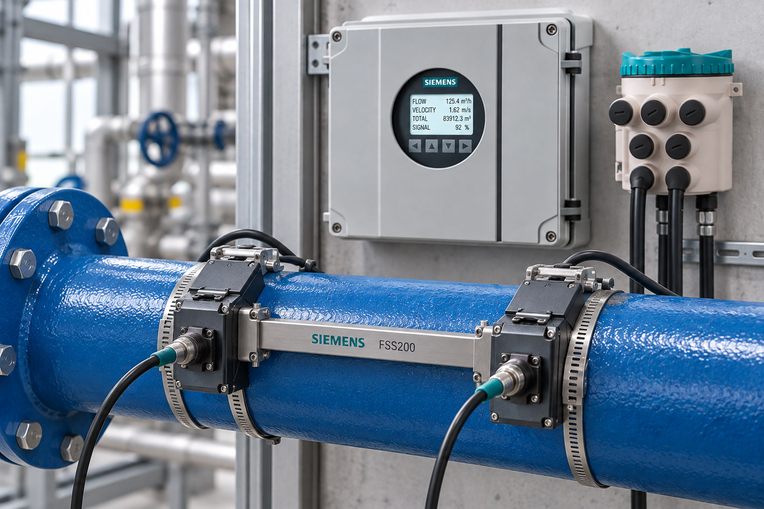
Clamp-on ultrasonic measurement is particularly suitable for existing pipelines because the sensors are mounted externally and the pipe does not need to be cut open or the process interrupted. In practice, however, such pipes are rarely bare and perfectly uniform. Steel pipes are often painted, provided with corrosion protection or have already been repainted several times. Rust spots, remnants of old coatings or uneven areas may also be present exactly where the ultrasonic sensors are to be installed.
This raises an important question: Must the paint be completely removed, or can a SITRANS clamp-on sensor be installed directly on a coated pipe? A general answer is not appropriate. A thin, firmly adhering and uniform coating is acoustically very different from loose old paint, corrosion or a thick, soft multilayer coating. What matters is not the colour of the pipe, but whether reproducible acoustic coupling can be established between the sensor and the actual pipe wall.
At the same time, the surface is only one part of the design. The SITRANS system requires correct information about pipe diameter, pipe material and wall thickness. For lined pipes, the data of the internal lining must also be taken into account. Even a significantly incorrect wall thickness changes the calculated ultrasonic path and can result in the sensor spacing and signal quality no longer matching optimally.
The most important rule is therefore: With coated pipes, the coupling point, actual pipe wall and parameterisation must be considered together. A clean sensor contact surface is of little benefit if an incorrect wall thickness has been entered. Conversely, perfect parameterisation cannot compensate for a loose or acoustically unsuitable contact surface.
How does SITRANS clamp-on measurement work?
With a clamp-on ultrasonic flowmeter, two ultrasonic sensors are mounted externally on the pipe. The sensors transmit ultrasonic signals through the pipe wall and the medium. From the transit times of the signals with and against the direction of flow, the transmitter determines the flow velocity and from this the volumetric flow rate.
The major advantage is that the sensors do not require direct contact with the medium. There is no additional pressure-loss point, the pipe does not need to be opened, and existing installations can be retrofitted comparatively easily.
However, this non-intrusive measurement must not be confused with a measurement that is independent of the pipe. The pipe itself is an essential part of the acoustic system. Material, outside diameter, wall thickness and, where applicable, internal lining together determine how the ultrasound propagates and at what spacing the sensors must be installed.
The external coupling point is also part of this acoustic path. Air between the sensor and pipe would be extremely unfavourable for ultrasonic transmission. The sensor surface, pipe surface and coupling material are therefore combined in such a way that a reproducible acoustic transition is created.
Is paint on the pipe fundamentally a problem?
A painted pipe is not automatically unsuitable for clamp-on measurement. The condition of the coating is decisive. A thin and completely firmly adhering paint layer on a smooth pipe can provide a considerably more favourable starting point than an uncoated but heavily corroded and flaking steel surface.
A coating becomes problematic primarily when it is no longer firmly bonded to the pipe wall or forms a highly uneven intermediate layer. Loose paint can move beneath the sensor mounting. Blisters, rust beneath the coating, thick multilayer coatings or soft coatings can further impair the acoustic contact.
For FSS200 installation, Siemens therefore requires a clean contact surface and explicitly identifies dirt, corrosion, rust and loose paint as materials that should be removed from the sensor area.
| Surface condition | Assessment for clamp-on measurement | Recommended action |
|---|---|---|
| Thin, smooth and firmly adhering paint | May be usable depending on signal quality and application | Clean the surface, establish the coupling point carefully and check the diagnostics |
| Loose or flaking paint | Unsuitable as a reproducible coupling point | Remove loose paint in the sensor area |
| Rust or corrosion beneath the coating | Uneven acoustic contact surface | Prepare the sensor surface correctly |
| Thick or soft multilayer coating | May strongly attenuate or unpredictably affect the ultrasound | Create a suitable local contact surface and verify signal quality |
| Bare, smooth and clean pipe | Very good initial condition | Install coupling material and sensor mounting according to the instructions |
It is therefore not sensible to automatically remove the entire coating over a large area from every painted pipe. However, it would be equally incorrect to assume that every existing paint layer can be used as a coupling surface without further consideration. The actual surface must be assessed on site.
Preparing the coupling point correctly
A good coupling point is clean, smooth, mechanically stable and as uniform as possible across the complete sensor surface. Grease, dirt, loose coating residues and corrosion particles must be removed.
For irregular pipe surfaces with old paint or corrosion, Siemens provides for mechanical surface preparation. However, restraint is important. A suitable hand sander or gentle abrasive treatment can be used. Aggressive treatment with an angle grinder or cutting grinder, on the other hand, is unsuitable because it can locally alter the pipe contour.
The objective is not to remove as much material as possible, but to create a flat and reproducible contact surface. Particularly with thin-walled pipes, surface preparation must never result in the removal of a relevant amount of pipe material.
The prepared area should be slightly larger than the actual sensor contact surface. This ensures that not only the central area of the sensor has clean contact, but that the surrounding mounting area also remains free of major irregularities.
After mechanical preparation, the surface is cleaned of abrasive dust, grease and loose particles. Only then are the coupling material and sensors installed.
Why the actual wall thickness is critical
The pipe wall thickness is not a secondary input parameter for clamp-on design. The ultrasound must pass through the pipe wall before reaching the medium. The wall thickness and acoustic velocity of the pipe material therefore influence the geometry and transit time of the acoustic path.
Where possible, the wall thickness should therefore not simply be taken from an old pipe list. Nominal wall thicknesses from pipe tables can be useful for an initial design, but they do not necessarily correspond exactly to the actual pipe. Manufacturing tolerances, corrosion loss and the actual pipe series can result in deviations.
Siemens therefore explicitly recommends determining the wall thickness using a suitable thickness gauge. If direct measurement is not possible, pipe-class tables can be used as substitute information.
This is particularly relevant for the high-precision FSS200 sensor versions for steel pipes. These are selected not only according to pipe diameter, but specifically according to wall-thickness range. An FSS200-C1H version, for example, is intended for a different wall-thickness range than a C2H or D version.
Important: The thickness of an external paint coating should not simply be added to the metallic pipe wall thickness and then entered as the pipe wall. The wall thickness describes the actual load-bearing pipe wall or the pipe material selected in the parameterisation. An internal lining is treated separately by suitable systems.
Distinguishing between external coating and internal lining
External paint and internal lining are sometimes treated as the same issue in practice. Acoustically and in terms of parameterisation, however, they represent different situations.
An external coating is located between the clamp-on sensor and the outside of the pipe wall. Its main influence is therefore at the coupling point. An internal lining, on the other hand, is located between the pipe wall and the medium and forms part of the actual acoustic path through the pipeline.
With the SITRANS FST030, separate parameters such as material, thickness and acoustic velocity can be entered for an internal lining. The available material groups include, for example, cement, enamel, glass, plastic, PTFE and rubber.
| Parameter | What does it mean? | Typical error |
|---|---|---|
| Outside diameter | External diameter of the pipe | Confusing nominal size with the actual outside diameter |
| Wall thickness | Thickness of the actual pipe wall | Simply adding paint or internal lining to the steel wall thickness |
| Pipe material | Material of the load-bearing pipe wall | Using the wrong material and therefore the wrong acoustic velocity |
| Liner thickness | Thickness of an internal lining | Completely ignoring an existing lining |
| Liner material | Material of the internal lining | Confusing the lining with the external coating |
| Coupling point | External contact surface between sensor and pipe | Leaving loose paint, rust or air gaps beneath the sensor |
A steel pipe that is painted externally but bare internally therefore does not automatically require liner parameterisation. The situation is different for a pipe that is internally rubber-lined, enamelled or lined with plastic.
Selecting the appropriate FSS200 sensor
The Siemens FSS200 family includes different sensor versions. The suitable version depends, among other things, on pipe material, diameter, wall thickness, temperature and accuracy requirements.
Universal sensors cover a wide range of pipe diameters and pipe materials and are suitable for many typical liquid applications. High-precision sensors are intended particularly for steel pipes and are selected according to defined wall-thickness ranges. Additional high-temperature versions are available for elevated pipe temperatures.
The coating alone therefore does not determine the sensor type. Correctly prepared painted steel can still represent a normal clamp-on application. What matters is the complete combination of pipe, medium, temperature, wall thickness and required measurement quality.
Using coupling material correctly
Even a very smooth metal surface is microscopically uneven. If an ultrasonic sensor is placed dry on such a surface, small air gaps remain. These air layers significantly impair ultrasonic transmission.
A suitable acoustic coupling material is therefore used between the sensor and pipe. Siemens offers different coupling materials for FSS200 applications depending on the application. For liquid measurement, these include dry couplant pads as well as suitable coupling compounds.
For permanently installed sensors, a coupling material intended for long-term installation should be used. The relevant factors are not only the acoustic properties immediately after installation, but also long-term behaviour, pipe temperature and environmental conditions.
More coupling material is not automatically better. Uniform and correctly installed coupling is what matters. Excessive soft material or an uneven sensor contact surface can impair reproducible positioning.
Selecting a suitable sensor position on the pipe
In addition to paint and wall thickness, the position on the pipe also affects signal quality. On horizontal liquid pipes, a clamp-on sensor should not simply be installed at the highest point of the pipe.
Gas bubbles tend to accumulate in the upper area, while deposits may concentrate in the lower area. A lateral installation – approximately near the 3 o’clock or 9 o’clock position – is therefore a favourable starting point for many liquid applications.
A section of pipe with a well-developed flow profile must also be selected. Valves, pumps, multiple bends or cross-sectional changes immediately upstream of the measuring point can significantly affect the velocity profile.
The optimum position therefore results from two requirements: firstly, the external surface must provide a suitable coupling point, and secondly, the hydraulic installation conditions must be suitable for reliable flow measurement.
Parameterising pipe and process data correctly
Before final installation, the relevant pipe and process data are entered into the transmitter. From these values, the system calculates, among other things, the required sensor spacing and intended acoustic path.
Depending on the system and application, important input data include in particular:
- pipe material,
- actual outside diameter,
- pipe wall thickness,
- material and thickness of an internal lining, where applicable,
- medium or acoustic velocity of the medium,
- process temperature,
- viscosity, where required for the particular configuration,
- positive flow direction.
Particularly in older installations, it should not automatically be assumed that the documentation contains all values correctly. Outside diameter and wall thickness can be verified on site. If there is any uncertainty, the actual pipe material should also be checked against the plant documentation.
After the parameters have been entered, the SITRANS system provides the required sensor spacing. This should then be implemented mechanically as accurately as possible. Mounting rails and sensor frames help achieve reproducible positioning.
The appropriate V, Z or W acoustic path depends, among other things, on pipe diameter, medium and signal conditions. This topic is covered in more detail in the separate technical article “Ultrasonic measurement using V, Z or W paths”.
Checking diagnostic values after installation
Once the sensors have been tightened, a clamp-on measuring point should not be accepted solely on the basis of a flow value that appears plausible. Particularly on coated pipes, the diagnostic values are valuable because they allow the quality of the actual acoustic transmission to be assessed.
With the SITRANS FST030, available diagnostic variables include receive gain, signal-to-noise ratio, acoustic velocity, transit time and transit-time difference. The received signal itself can also be viewed diagnostically.
| Diagnostic value | Meaning | What may indicate a problematic coupling point? |
|---|---|---|
| RX Gain | Required amplification of the received signal | Unusually high gain requirements may indicate a weak signal |
| SNR | Signal-to-noise ratio | A low value may indicate poor acoustic conditions or interference |
| Receiver Signal | Shape of the received ultrasonic signal | A weak or unclear signal may require the installation to be checked again |
| Sound Velocity | Determined acoustic velocity of the medium | Implausible values may indicate incorrect parameters or an unsuitable measuring condition |
| Travel Time | Transit time between transmission and reception | Helps verify the plausibility of the acoustic path and parameterisation |
The diagnostic values should not be assessed in isolation using a single limit value. Pipe size, sensor type, medium and installation all influence the signal. Comparing the values before and after changing the sensor position or preparing the surface is particularly useful.
If, for example, the signal-to-noise ratio improves significantly after a loose paint layer has been removed locally and the coupling point re-established, this is a strong indication that the original surface had a relevant influence.
Practical example: painted cooling-water pipe
In an existing installation, the flow rate of a cooling-water line is to be measured. The steel pipe is coated externally with several layers of corrosion-protection paint. Cutting the pipe to install an inline flowmeter is to be avoided.
At first glance, the paint surface appears to be in good condition. On closer inspection, however, individual areas show corrosion beneath the coating and slight local blistering. Clamping a sensor exactly at these points would be unfavourable because the mechanical and acoustic connection would not be clearly reproducible.
A suitable lateral measuring point with a sufficiently straight pipe run is therefore selected first. The actual outside diameter is recorded and the wall thickness is verified using a suitable measuring method. The two intended sensor areas are then prepared locally so that loose coating and corrosion are removed and a smooth, stable contact surface is created.
After the pipe material, diameter, wall thickness and medium have been entered, the SITRANS transmitter calculates the sensor spacing. The sensors are installed using suitable coupling material, and not only the flow value but also the signal diagnostics are then checked.
If the received signal is stable and the determined acoustic velocity is plausible for the medium, the measuring point has a considerably stronger technical basis than an installation in which two sensors have simply been clamped onto the existing old paint and a seemingly plausible flow value accepted.
Systematic installation and testing procedure
For coated pipes, it is advisable to check the surface, pipe data and diagnostics in a defined sequence. This prevents troubleshooting situations in which the sensor position, parameterisation and coupling point are all changed at the same time.
- Select a suitable pipe section: Consider a straight pipe run, a completely filled pipe and a favourable sensor position.
- Determine the pipe material: Verify the material using documentation or plant identification.
- Determine the outside diameter: Use the actual value rather than only the nominal diameter.
- Determine the wall thickness: Measure where possible; use pipe tables only as a substitute.
- Check the internal lining: If present, record its material and thickness separately.
- Assess the coating condition: Check for loose paint, blisters, corrosion and uneven multilayer coatings.
- Prepare the coupling areas: Clean the surface and correctly remove loose or interfering layers.
- Enter the pipe and process data: Store the parameters correctly in the SITRANS transmitter.
- Apply the calculated sensor spacing: Set the calculated spacing mechanically as accurately as possible.
- Install the coupling material: Use material suitable for the application and temperature.
- Mount the sensors evenly: Ensure full-area and reproducible acoustic coupling.
- Check the diagnostics: Verify the plausibility of the received signal, SNR, gain and acoustic velocity.
- Assess the flow value: Only consider the measured value reliable after successful diagnostic checks.
- Document the installation: Record pipe data, sensor position and diagnostic values for future maintenance.
Common errors with coated pipes
Completely removing every paint coating as a matter of principle
The paint itself is not the problem; an unsuitable acoustic contact surface is. Adhesion, uniformity and signal quality are decisive. Unnecessary large-scale damage to the corrosion protection should be avoided.
Leaving loose old paint beneath the sensor
A movable or under-corroded coating is not a stable coupling point and should be correctly prepared in the sensor area.
Creating a flat surface using an angle grinder
Aggressive grinding can alter the pipe contour and even locally reduce the wall thickness. The surface should be cleaned and smoothed, not unnecessarily machined.
Deriving the wall thickness from the nominal diameter
The wall thickness cannot be determined uniquely from DN alone. Pipe series, schedule and actual design must be taken into account.
Adding the external paint thickness to the steel wall thickness
The paint coating is not simply part of the metallic pipe wall entered in the parameterisation.
Overlooking the internal lining
Rubber, PTFE, cement, enamel or other internal linings lie directly in the acoustic path and must be considered separately in suitable systems.
Installing the sensor on top of a horizontal liquid pipe
Gas bubbles tend to collect at the top of the pipe and may interfere with the ultrasonic path. A lateral installation is often more favourable.
Considering only a plausible flow value
A numerical value may appear plausible even when the received signal is poor. Diagnostic values form part of the commissioning process for a clamp-on measuring point.
Using coupling material as a substitute for poor surface preparation
Coupling material is intended to bridge microscopic air gaps. It cannot reliably compensate for loose paint, severe corrosion or an unsuitable mechanical contact surface.
Suitable SITRANS clamp-on systems
ICS Schneider Messtechnik offers various Siemens SITRANS clamp-on systems for non-intrusive ultrasonic flow measurement.
The SITRANS FS220 combines the FST020 transmitter with FSS200 clamp-on ultrasonic sensors. The system is particularly suitable for typical liquid applications where an existing pipeline is to be retrofitted without interrupting the process.
For more demanding applications, the SITRANS FS230 with FST030 transmitter and FSS200 sensors is available. Depending on the configuration, multiple measuring paths, extensive diagnostic functions and versions for hazardous areas are possible.
Within the FSS200 sensor family, universal, high-precision and high-temperature versions are available. The appropriate version depends, among other things, on pipe material, pipe diameter, wall thickness, temperature and required measurement accuracy.
Siemens ultrasonic flow measurement at ICS Schneider
Conclusion
A painted or otherwise coated pipe does not fundamentally prevent clamp-on ultrasonic measurement. However, measurement quality depends on what is actually located between the sensor and the pipe wall and how reproducibly the acoustic contact can be established.
Loose paint, corrosion and uneven surfaces should not be located beneath a clamp-on sensor. A thin, mechanically stable surface, on the other hand, must be assessed according to the specific application and achievable signal quality.
The correct pipe wall thickness is just as important as the coupling point. Ultrasonic measurement uses the pipe itself as part of the acoustic path. Incorrect wall data can therefore impair the sensor spacing and acoustic design. With high-precision FSS200 sensors for steel pipes, wall thickness is even a direct selection criterion for the sensor version.
External coating and internal lining must also be considered separately. The external paint mainly affects the mechanical and acoustic coupling of the sensor. An internal lining, by contrast, lies directly in the acoustic path and is taken into account with its own material and thickness values in suitable SITRANS systems.
Anyone who checks the pipe material, outside diameter, actual wall thickness and coating condition before installation, prepares the contact surface carefully and then checks the SITRANS diagnostic values will create a considerably more robust measuring point than one installed purely by visual judgement.
FAQ on SITRANS clamp-on installation on coated pipes
Can a SITRANS clamp-on sensor be installed directly on paint?
This depends on the condition and structure of the coating. A thin, smooth and completely firmly adhering coating can represent a different situation from loose old paint or a thick, soft coating. Siemens specifically requires loose paint, rust, corrosion and dirt to be removed from the sensor area.
Does the paint always have to be completely removed for clamp-on measurement?
No. A general requirement to remove every coating completely is not appropriate. What matters is a mechanically stable and acoustically suitable contact surface. If signal quality is poor or the coating is uncertain, the coupling point should be prepared locally as required.
Can I add the paint thickness to the pipe wall thickness?
No. The pipe wall thickness used in the parameterisation describes the actual pipe wall of the selected pipe material. An external coating should not simply be treated as additional steel wall thickness.
What is the best way to determine the wall thickness?
Siemens recommends measurement using a suitable wall-thickness gauge. If this is not possible, pipe-class tables or documented pipe data can be used.
Why is the wall thickness so important for clamp-on measurement?
The ultrasound passes through the pipe wall. The wall thickness and acoustic velocity of the pipe material therefore influence the acoustic path and the calculated sensor spacing.
What is the difference between an external coating and an internal lining?
The external coating is located between the sensor and the outside of the pipe wall and mainly affects the coupling point. An internal lining is located between the pipe wall and the medium and is directly part of the ultrasonic acoustic path.
Can SITRANS take an internal lining into account?
With suitable SITRANS systems, the material, thickness and acoustic properties of an internal lining can be parameterised separately.
Which internal linings may be relevant?
Typical examples include rubber, plastic, PTFE, cement, glass or enamel. The actual pipe and the material data available for the transmitter being used are decisive.
Can I simply compensate for rust using coupling material?
No. Coupling material is used to establish acoustic contact between suitable surfaces. Loose corrosion and highly uneven surfaces should be prepared correctly beforehand.
May the pipe surface be prepared using an angle grinder?
When preparing the FSS200 coupling point, Siemens advises against electric grinders or angle grinders that may alter the pipe contour. A gentler abrasive preparation method can be used for irregular old surfaces.
Where should the sensors be positioned on a horizontal liquid pipe?
A lateral position is often more favourable than the highest or lowest point of the pipe. Gas bubbles can collect at the top of the pipe, while deposits may be present at the bottom.
Which coupling material should be used?
The coupling material must suit the sensor version, application, temperature and intended installation duration. For permanent installations, a correspondingly suitable permanent coupling material should be used.
Which diagnostic values are important after installation?
Depending on the SITRANS system, values such as RX Gain, signal-to-noise ratio, received signal, acoustic velocity, transit times and transit-time difference can be checked. These values help assess the quality of the acoustic coupling and parameterisation.
Can a plausible flow value be displayed despite poor coupling?
Yes. For this reason, a new clamp-on measuring point should not be assessed solely on the basis of the displayed flow rate. The available diagnostic values should also be checked for plausibility.
When should a high-precision FSS200 sensor be used?
These sensor versions are intended particularly for higher accuracy requirements on steel pipes. Selection is based on the actual pipe wall thickness.
When is the SITRANS FS220 suitable?
The FS220 is suitable for typical stationary clamp-on liquid measurements and combines the FST020 transmitter with FSS200 sensors.
When is the SITRANS FS230 suitable?
The FS230 is suitable for more demanding clamp-on applications with extended diagnostic, communication and multipath options and, depending on the version, for hazardous areas.