


The quality of compressed air cannot be assessed solely on the basis of its dew point. Even when the air is sufficiently dry, solid particles, oil aerosols, liquid oil or oil vapours can still adversely affect products, machines and processes.
ISO 8573-1 therefore defines three independent purity classes: particles, water and oil. Compressed-air quality is specified, for example, as ISO 8573-1:2010 [2:2:1]. The first digit represents particles, the second water and the third the total oil content.
For such a specification to be reliable, the measuring point, sampling method, measuring pressure, flow rate, operating condition and measuring methods used must be documented. A single instantaneous value downstream of a new filter is not sufficient to demonstrate the compressed-air quality of an entire network or a critical consumer.
Measurement and monitoring systems can be found in the ICS category Compressed-Air Quality. Instruments for measuring flow and consumption are grouped under Consumption Meters for Gases and Compressed Air.
Table of Contents
- What does ISO 8573-1 specify?
- How is a purity class specified?
- What does Class 0 mean?
- Correctly assessing particle classes
- Correctly measuring particles in compressed air
- Water classes and pressure dew point
- Distinguishing between water vapour and liquid water
- Oil classes and total oil content
- Measuring oil aerosols and oil vapour separately
- Selecting the correct measuring point
- Correctly designing the sampling system
- Detecting temporary contamination loads
- Distinguishing between indicative measurements and ISO verification
- Food, pharmaceutical, painting and electronics applications
- Measures for inadequate compressed-air quality
- Practical example: Verifying purity class 2:2:1
- Typical errors in compressed-air quality measurements
- What should be included in the test report?
- Which products and solutions are suitable?
- Conclusion
- Frequently asked questions
What does ISO 8573-1 specify?
ISO 8573-1 defines purity classes for compressed air. It does not describe the construction of a compressor or filter, but rather the contamination actually present at a defined point in the compressed-air system.
The three primary contamination groups are:
- particles,
- water,
- oil.
The ISO 8573 series also covers measuring methods for gaseous and microbiological contaminants. However, these are not fully covered by the conventional three-digit purity classification for particles, water and oil.
The standard does not prescribe one universal purity class for a particular industry. The operator must derive the required quality from process requirements, product risk, statutory requirements, customer specifications and the company’s quality-management system.
The required class may vary within the same plant. General control air may require a different quality from compressed air in direct contact with a product or air used in a highly sensitive painting process.
How is a purity class specified?
The purity class is stated in the order particles, water and oil:
ISO 8573-1:2010 [A:B:C]
- A: particle class,
- B: water class,
- C: total oil class.
The example:
ISO 8573-1:2010 [1:2:1]
means:
- The particles must meet the requirements of Class 1.
- The pressure dew point must meet Water Class 2.
- The total oil content must meet Oil Class 1.
The digits must not be combined into one overall class. A system may, for example, achieve Class 2 for water, but only Class 3 for particles and Class 1 for oil.
If no class has been agreed or measured for a parameter, this should be clearly indicated. An omitted parameter does not automatically correspond to Class 0.
What does Class 0 mean?
Class 0 does not mean that the compressed air is completely free of particles, water or oil. It describes a requirement agreed in writing between the user and supplier that must be more stringent than Class 1 for the relevant parameter.
A correct Class 0 specification must therefore include at least:
- the relevant contamination parameter,
- the agreed maximum value,
- the unit,
- the measuring method,
- the measuring point,
- the operating and reference conditions.
The statement “Class 0 compressed air” on its own is technically incomplete. It does not indicate whether the requirement applies to particles, water, oil or several parameters.
Even a compressor described as oil-free does not automatically guarantee a particular oil class at the consumer. Hydrocarbons can enter the compressed-air network through the intake air, contaminated piping, old receivers, sealants or other components.
Correctly assessing particle classes
For the more stringent particle classes, the number of particles within defined size ranges per cubic metre of compressed air is assessed.
| Particle class | 0.1 to 0.5 µm | 0.5 to 1.0 µm | 1.0 to 5.0 µm |
|---|---|---|---|
| 0 | Individually specified value, more stringent than Class 1 | ||
| 1 | max. 20,000 particles/m³ | max. 400 particles/m³ | max. 10 particles/m³ |
| 2 | max. 400,000 particles/m³ | max. 6,000 particles/m³ | max. 100 particles/m³ |
| 3 | not specified | max. 90,000 particles/m³ | max. 1,000 particles/m³ |
| 4 | not specified | not specified | max. 10,000 particles/m³ |
| 5 | not specified | not specified | max. 100,000 particles/m³ |
For higher particle loads, the classes are assessed on the basis of mass concentration in mg/m³. Particle counting and mass determination are different measuring tasks and must not be substituted for one another arbitrarily.
Compliance with a particle class is always determined by the least favourable relevant size range. If two ranges comply with Class 1 but the third only complies with Class 2, the result is Particle Class 2.
Correctly measuring particles in compressed air
Particle counts are usually determined using a suitable optical particle counter with a sampling system designed for compressed air. The measurement and sampling system must be appropriate for the pressure, expected particle concentration and required size channels.
The following points in particular must be considered:
- representative sampling from the main flow,
- suitable pressure adaptation without particle loss,
- short and clean sampling lines,
- avoidance of dead spaces and deposition points,
- sufficient flushing time,
- a suitable measuring range for the particle counter,
- valid calibration,
- a sufficiently long measuring period.
Arbitrary pressure reduction can alter the result. Particles can be deposited inside valves and throttles, newly generated by high flow velocities or lost through unsuitable piping.
The measuring method according to ISO 8573-4 records particles by size and concentration. It does not automatically distinguish between solid particles and liquid droplets. Water or oil aerosols can therefore influence the particle result.
At high particle concentrations, the mass concentration may need to be determined instead of the particle count. Different sampling and evaluation methods apply in this case.
Water classes and pressure dew point
For dry compressed air, Water Classes 1 to 6 are determined on the basis of the pressure dew point.
| Water class | Maximum pressure dew point |
|---|---|
| 0 | Individually specified value, more stringent than Class 1 |
| 1 | ≤ −70 °Ctd |
| 2 | ≤ −40 °Ctd |
| 3 | ≤ −20 °Ctd |
| 4 | ≤ +3 °Ctd |
| 5 | ≤ +7 °Ctd |
| 6 | ≤ +10 °Ctd |
Classes 7 to 9, by contrast, relate to liquid water or its mass concentration. A dew-point measurement alone cannot quantitatively determine liquid water.
The pressure dew point describes the temperature at which water vapour begins to condense at the pressure present at the measuring point. The measuring pressure must therefore be documented.
A dew-point value measured after pressure reduction must not be compared with a limit value at line pressure without conversion.
Distinguishing between water vapour and liquid water
A dew-point or moisture measuring method is used to assess water vapour. The measuring point should have a continuous gas exchange and receive representative compressed air from the main line.
A suitable arrangement is:
Main line → shut-off valve → short stainless-steel line → measuring chamber with dew-point sensor → flow restriction → exhaust
For a pressure-dew-point measurement, the flow restriction is located downstream of the sensor. This keeps the pressure inside the measuring chamber approximately equal to the pressure in the main line.
Errors are caused in particular by:
- long plastic hoses,
- stagnant branch lines,
- leaks allowing ambient air to enter,
- incomplete flushing,
- condensate on the sensor,
- oil or particle deposits,
- pressure reduction upstream of the sensor.
Liquid water must be considered separately. Condensate droplets may be present inside the piping even though a remotely installed dew-point sensor indicates an apparently plausible value.
For a complete assessment, the dryer, water separator, filters, condensate drains and piping arrangement must therefore also be inspected.
Oil classes and total oil content
The oil class relates to the total oil content comprising liquid oil, oil aerosols and oil vapour.
| Oil class | Maximum total oil content |
|---|---|
| 0 | Individually specified value, more stringent than Class 1 |
| 1 | ≤ 0.01 mg/m³ |
| 2 | ≤ 0.1 mg/m³ |
| 3 | ≤ 1 mg/m³ |
| 4 | ≤ 5 mg/m³ |
| X | > 5 mg/m³ |
The concentrations must be referenced to the specified reference conditions. Measured values from different instruments are only comparable when the unit, reference pressure, reference temperature and moisture reference are identical.
An instrument that measures only oil vapour cannot confirm the total oil class on its own. Likewise, an aerosol measurement does not automatically detect all gaseous hydrocarbons.
Measuring oil aerosols and oil vapour separately
Liquid oil and oil aerosols are determined using different methods from oil vapour.
Liquid oil and oil aerosols
Suitable collection methods are used for liquid oil and aerosols. The oil is separated, for example, using coalescence filters or defined sampling discs and is then quantitatively analysed.
Oil vapour
Oil vapour consists of gaseous hydrocarbons. For standards-based verification, pressurised sampling followed by gas-chromatographic analysis may be required.
Continuous oil-vapour monitoring systems are particularly suitable for operational monitoring and the early detection of deterioration downstream of activated-carbon filters or adsorbers.
For the total oil assessment, the following simplified relationship applies:
Total oil = liquid oil + oil aerosol + oil vapour
Example:
- oil aerosol and liquid oil: 0.004 mg/m³,
- oil vapour: 0.005 mg/m³,
- total oil: 0.009 mg/m³.
This fulfils the requirements of Oil Class 1. If only the oil-vapour value were considered, the assessment would be incomplete.
Selecting the correct measuring point
The determined purity class applies only to the tested measuring point and the documented operating condition.
Upstream of the treatment system
A measurement upstream of the filters and dryer shows the contamination load entering the treatment system. It is suitable for root-cause analysis and system design, but does not confirm the quality at the consumer.
Directly downstream of the treatment system
This measuring point assesses the performance of filters, dryers and adsorbers. Subsequent contamination from receivers or piping is not detected.
In the main distribution system
A measurement in the main distribution system also takes storage receivers, the piping network and central distributors into account.
At the critical consumer
For applications involving product contact or particularly sensitive processes, the measuring point immediately upstream of the consumer is often decisive.
The following contamination can occur between the central treatment system and the consumer:
- corrosion particles,
- water from low points in the piping,
- oil residues from old piping,
- moisture ingress from stagnant branches,
- contamination from local compressors or external networks.
Several measuring points are therefore often required for a complete plant assessment.
Correctly designing the sampling system
Sampling is an essential part of the measurement. High-quality measuring instruments cannot compensate for an unsuitable sampling point.
The following points should generally be considered:
- sampling from a representative, continuously flowing pipe section,
- no long, closed branch line,
- short and clean stainless-steel sampling lines,
- no condensate traps or deep loops,
- gas-tight fittings,
- a defined measuring-gas flow rate,
- sufficient flushing and stabilisation time,
- suitable pressure and temperature conditions,
- no unsuitable filters or throttles upstream of the sample.
Different sampling arrangements may be required for particles, moisture and oil. A single sampling line with arbitrary pressure reduction is therefore not automatically suitable for all three measurements.
The hoses, seals and valves used can also influence the result. Plastic materials can absorb moisture or hydrocarbons and release them again later.
Detecting temporary contamination loads
Compressed-air quality can change during operation. A brief measurement under favourable conditions does not necessarily detect the worst-case condition.
Relevant operating events include:
- starting and stopping the compressor,
- load and idle transitions,
- switching of an adsorption dryer,
- regeneration phases,
- high ambient temperatures,
- saturated filters or activated carbon,
- malfunctioning condensate drains,
- temporarily open bypass lines,
- production peaks with high compressed-air consumption.
With dryers, the pressure dew point may briefly rise during a switching cycle. Oil and particle contamination may be elevated during compressor start-up or after maintenance work.
For audit verification, the measuring period should therefore cover a representative operating period or complete system cycles.
Distinguishing between indicative measurements and ISO verification
An indicative measurement is used for a quick condition check, troubleshooting or trend monitoring. It can be performed using portable or continuous measuring instruments.
Reliable verification of a purity class additionally requires:
- defined measuring methods,
- suitable sampling,
- traceably calibrated measuring instruments,
- documented measurement uncertainty,
- a representative measuring period,
- complete operating data,
- separate assessment of each contamination parameter.
A display showing “ISO Class 1” is not, on its own, complete verification. It must be clear which type of contamination the instrument measured and which other components may not have been detected.
Continuous monitoring and periodic ISO testing complement one another:
- Monitoring: detects changes and malfunctions during ongoing operation.
- Periodic testing: documents the achieved quality using a defined test procedure.
Food, pharmaceutical, painting and electronics applications
There is no single ISO 8573 class that applies universally to all food, pharmaceutical, electronics or painting processes.
The decisive factors include:
- direct or indirect product contact,
- risk of sensory impairment,
- microbiological requirements,
- sensitivity of coatings and paints,
- permissible particle size at the product,
- process temperature and condensation risk,
- customer-specific quality agreements,
- HACCP, GMP or internal risk assessments.
For direct product contact, a microbiological investigation may also be required in addition to particle, water and oil measurements. A good particle class does not automatically prove the absence of viable microorganisms.
The purity class should therefore be defined as a specific technical specification for every relevant point of use.
Measures for inadequate compressed-air quality
Elevated particle contamination
- Check the filter elements and filter differential pressure.
- Inspect the piping network for corrosion and deposits.
- Consider desiccant abrasion downstream of adsorption dryers.
- Clean or replace piping and receivers.
- Install filters immediately upstream of critical consumers.
Pressure dew point too high
- Check the dryer function and operating condition.
- Check the condensate drains.
- Inspect bypass valves and external air feeds.
- Inspect the measuring point for leaks and dead spaces.
- Adapt the dryer capacity to the actual volumetric flow rate.
Oil content too high
- Check oil separators and coalescence filters.
- Check the compressor temperature and maintenance condition.
- Replace activated-carbon filters or adsorbers.
- Consider old piping contaminated with oil.
- Analyse oil aerosols and oil vapour separately.
After a corrective measure, the measurement must be repeated under comparable conditions. Replacing a filter alone does not prove that the agreed purity class is achieved at the consumer.
Practical example: Verifying purity class 2:2:1
The following requirement was defined for a packaging system on the basis of the company’s risk assessment:
ISO 8573-1:2010 [2:2:1]
The measuring point is located immediately upstream of the critical consumer. The system is tested during a complete production cycle.
Particle measurement
- 0.1 to 0.5 µm: 120,000 particles/m³,
- 0.5 to 1.0 µm: 1,800 particles/m³,
- 1.0 to 5.0 µm: 35 particles/m³.
All values comply with Particle Class 2. Particle Class 1 is not achieved because of the first size range.
Water measurement
The stabilised pressure dew point is −44 °Ctd at line pressure. Water Class 2 is therefore achieved.
Oil measurement
- oil aerosol and liquid oil: 0.020 mg/m³,
- oil vapour: 0.015 mg/m³,
- total oil: 0.035 mg/m³.
The total oil content only meets the requirements of Oil Class 2. The required Oil Class 1 with a maximum of 0.01 mg/m³ is not achieved.
The overall result is therefore:
ISO 8573-1:2010 [2:2:2]
During the root-cause analysis, a saturated activated-carbon filter is identified. After replacement and sufficient flushing time, the following values are measured:
- oil aerosol and liquid oil: 0.002 mg/m³,
- oil vapour: 0.004 mg/m³,
- total oil: 0.006 mg/m³.
The agreed quality of ISO 8573-1:2010 [2:2:1] is therefore achieved.
The example demonstrates that a good dew point alone does not provide any information about the total oil content.
Typical errors in compressed-air quality measurements
| Error | Possible consequence | Suitable corrective action |
|---|---|---|
| Only the dew point is measured | Particle and oil contamination remain unknown | Test all agreed contamination parameters separately |
| Measurement only directly downstream of the treatment system | Contamination inside the piping network is not detected | Also measure at the critical consumer |
| Oil-vapour value interpreted as total oil | Oil aerosols and liquid oil are omitted from the assessment | Combine the aerosol, liquid and vapour fractions |
| Particle counter connected through an unsuitable throttle | Particles are deposited or newly generated | Use standards-compliant sampling |
| Long plastic line used for dew-point measurement | Moisture diffusion and a long stabilisation time | Use a short stainless-steel line |
| Pressure reduced upstream of the dew-point sensor | Incorrect reference to the pressure dew point in the main line | Perform the measurement at a defined line pressure |
| Class 0 treated as “free from contamination” | Incomplete and unverifiable specification | Define a specific limit and measuring method |
| Measurement performed only at low plant load | Peak contamination is not detected | Test a representative operating cycle |
| Different reference conditions compared | Apparent deviations between measuring instruments | Align the reference pressure, temperature and unit |
| Instrument reading accepted without measurement uncertainty | The decision regarding compliance with the limit is not reliable | Document the calibration status and measurement uncertainty |
What should be included in the test report?
A traceable test report should contain at least:
- the customer, plant and purpose of the measurement,
- the date and responsible person,
- the required ISO 8573-1 class,
- the edition of the standard used,
- a clear description of the measuring point,
- the measuring methods for particles, water and oil,
- the instrument designation, serial number and calibration status,
- the line pressure and gas temperature,
- the measuring-gas flow rate and sampling-line configuration,
- the operating condition of the compressor, dryer and filters,
- the measuring period and system cycles considered,
- the individual values and statistical evaluation,
- the reference conditions for the concentration values,
- the measurement uncertainty and detection limits,
- the achieved class for each contamination parameter,
- deviations and recommended measures.
The achieved class should only be stated after all relevant individual values have been assessed.
Which products and solutions are suitable?
IFA510 and IFA515 dew-point sensors
The IFA510 and IFA515 for adsorption dryers measure pressure dew points within a range of −80 to +20 °Ctd. They are suitable for continuously monitoring very dry compressed air and, depending on the version, provide 4–20 mA and Modbus RTU signals.
For refrigeration dryers, IFA510 and IFA515 versions with a measuring range of −20 to +50 °Ctd are available.
A suitable measuring chamber with a defined gas flow improves reproducibility and facilitates removal for calibration.
IDP500 portable dew-point meter
The IDP500 is designed for portable dew-point and long-term measurements down to −80 °Ctd. The integrated data logger enables dryer cycles to be recorded and stationary measuring points to be checked.
OIL CHECK 500
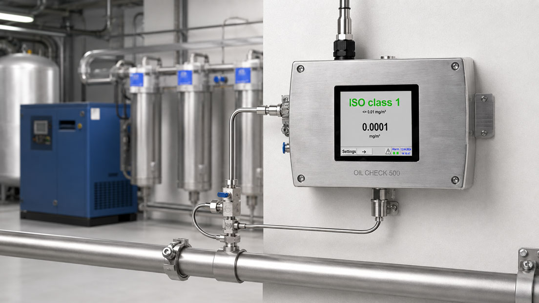
The OIL CHECK 500 measures the vaporous residual oil content in treated compressed air and nitrogen. The measuring range is 0.001 to 5 mg/m³, and the detection limit is 0.001 mg/m³.
The instrument is particularly suitable for continuous monitoring downstream of activated-carbon filters, activated-carbon adsorbers or oil-free compressors with suitable upstream filtration and drying.
Because the system measures the vaporous residual oil fraction, the oil-aerosol and liquid-oil fractions must additionally be considered for complete verification of the total oil class.
IVA520 and IVA570 consumption meters
A flow or consumption meter such as the IVA520 or the IVA570 does not directly measure the purity class. It does, however, provide important additional information about the volumetric flow rate, consumption peaks and operating condition during a quality measurement.
This makes it possible to determine whether the required compressed-air quality is also maintained at high plant loads or during typical production cycles.
Particle measurement
Particle classification requires a particle measuring system suitable for compressed air and an appropriate high-pressure sampling system. The measuring range, size channels and sampling arrangement are adapted to the required ISO class on a project-specific basis.
ICS Schneider Messtechnik provides support in planning measuring points for particles, pressure dew point and residual oil, as well as defining the measuring period, sampling method, reference conditions and documentation.
Conclusion
Compressed-air quality according to ISO 8573-1 is described by three independent values for particles, water and oil. A dew-point measurement alone is therefore not sufficient for a complete assessment.
Depending on the class, particles must be determined either by their number within defined size ranges or by their mass concentration. The sampling system must neither remove particles nor generate additional particles.
For water, a distinction must be made between water vapour and liquid water. The pressure dew point must always be considered together with the measuring pressure.
The oil class relates to the total oil content comprising liquid oil, aerosols and oil vapour. An oil-vapour monitor alone can therefore only provide part of the total oil assessment.
The purity class applies exclusively to the tested measuring point and the documented operating condition. For critical processes, measurements should be performed not only downstream of the treatment system but also immediately upstream of the relevant consumer.
Reliable audit verification requires suitable measuring methods, calibrated instruments, representative operating conditions, documented measurement uncertainty and a complete test report.
Frequently asked questions about compressed-air quality according to ISO 8573
What does ISO 8573-1 [1:2:1] mean?
The first digit represents the particle class, the second the water class and the third the total oil class.
Is Class 0 completely free from contamination?
No. Class 0 is an individually specified requirement that must be more stringent than Class 1. The specific limit must be stated in writing.
Is a good pressure dew point sufficient as proof of quality?
No. A good pressure dew point only confirms the water content under the measured conditions. Particles and oil must be determined separately.
What is included in the total oil content?
The total oil content includes liquid oil, oil aerosols and oil vapour. The results of the relevant measuring methods must be combined for classification.
Can the OIL CHECK 500 verify the oil class on its own?
The instrument measures the vaporous residual oil fraction. For complete verification of the total oil class, oil aerosols and liquid oil must additionally be considered.
Where should compressed-air quality be measured?
The measuring point depends on the measurement objective. The performance of the treatment system is assessed downstream of the filters and dryer. For process quality, the point immediately upstream of the critical consumer is often decisive.
Why is the measuring pressure important for dew-point measurements?
The dew point changes with pressure. A value measured after pressure reduction cannot be compared with the pressure dew point in the main line without conversion.
Can a particle counter also count oil or water droplets?
Yes. An optical particle measuring method does not automatically distinguish between solid particles and liquid aerosols. The sampling method and interpretation must take this into account.
How long should a compressed-air quality measurement take?
The measuring period must cover representative operating conditions. For cyclically operating dryers or varying compressor loads, complete plant cycles should be considered.
Does ISO 8573 specify a mandatory class for food applications?
No. The required class must be derived from product contact, risk assessment, customer requirements and the company’s hygiene concept.
Is an oil-free compressor sufficient for Oil Class 0 or 1?
Not automatically. Hydrocarbons can enter the system through the intake air, piping, receivers and other components. The measured quality at the specified point is decisive.
Must compressed-air quality be tested regularly?
For quality-critical applications, a defined test interval should be established. Continuous sensors can supplement monitoring but do not replace a complete periodic test in every case.