


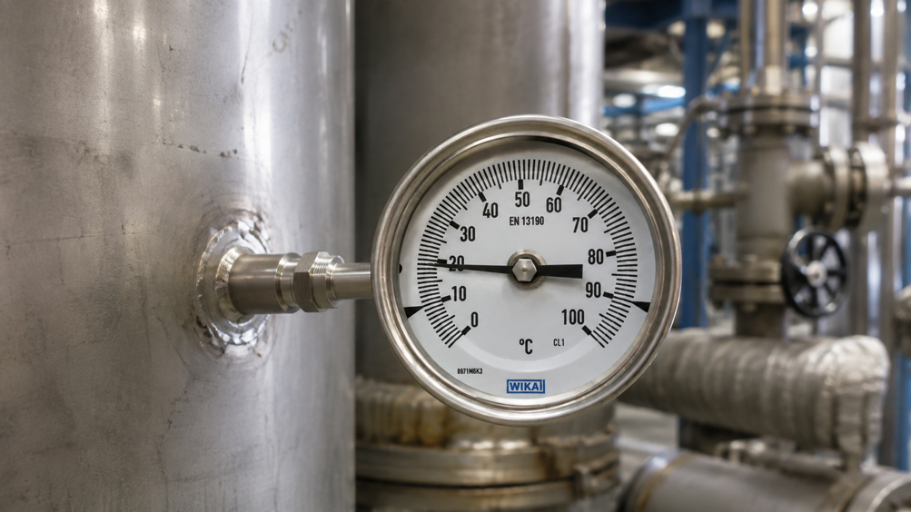
A dial thermometer is correctly installed in the pipeline.
The stem is positioned in the process, the measuring range is suitable and the instrument indicates a plausible value.
Nevertheless, the dial is barely readable from the operator walkway.
The obvious solution:
Rotate or swivel the case
With a dial thermometer designed for this purpose, this is exactly what is possible.
The adjustable version allows the stem and process connection to remain mechanically correct in the process while the dial is aligned to the desired viewing angle.
However, the case must not simply be forced into a different position.
With rotatable and swiveling thermometers:
- the joint must be loosened correctly,
- the display must be positioned without mechanical stress,
- the available installation space must be taken into account,
- the stem must remain unchanged in the process,
- the connection must then be securely fixed again
.
It is equally important to distinguish between:
alignment of the case
and:
thermally correct position of the stem
.
An optimally aligned dial will not provide a correct temperature value if the stem is too short, the active length is not sufficiently exposed to the medium or heat is dissipated through the connection.
Suitable instruments can be found at ICS Schneider under Temperature Measurement Technology and specifically under Dial Thermometers.
Table of Contents
- Why use an adjustable dial thermometer?
- Distinguishing axial, radial and adjustable versions
- How does the adjustment joint work?
- Correctly adjusting a rotatable and swiveling thermometer
- Why the case must not simply be twisted
- Viewing angle and parallax error
- Considering installation space during selection
- Correctly positioning the stem and active measuring length
- Selecting the correct insertion length
- Installation in pipelines
- Thermometers with thermowells
- Avoiding mechanical stress
- Vibration and pointer damping
- Considering ambient temperature at the case
- Do not confuse zero-point correction with case alignment
- Maintenance and repositioning
- Recommended installation and inspection procedure
- Typical error patterns
- Practical example: thermometer on a difficult-to-access pipeline
- Suitable ICS products
- Conclusion
- FAQ
Why use an adjustable dial thermometer?
With a fixed dial thermometer, the position of the dial is largely determined by:
- process connection,
- pipeline direction,
- installation position,
- position of the connection nozzle
.
This is not a problem as long as the display remains clearly visible.
In real installations, however, the measuring point is often located
- under a pipeline,
- behind a valve,
- close to a wall,
- between several pipes,
- above head height,
- inside a machine enclosure.
A fixed case can then be positioned unfavorably
for example:
Dial faces the wall
or:
Dial is positioned almost horizontally
A rotatable and swiveling version, by contrast, allows
the process connection and the display orientation to be largely decoupled from one another.
This is particularly practical for
- operators,
- maintenance,
- commissioning,
- regular inspection rounds,
- difficult-to-access plant areas.
Distinguishing axial, radial and adjustable versions
Dial thermometers are available with different connection orientations.
Axial version
The stem is located at the rear behind the dial.
In simplified form:
Dial → Stem
Radial version
The stem typically exits from the bottom of the case.
The case is therefore positioned approximately:
90° to the stem
Rotatable and swiveling version
A joint is located between the stem or process connection and the case.
This allows the display to be adjusted to the viewing line after installation.
Important
“Rotatable and swiveling” means a device version specifically designed for this purpose. A standard axial or radial case must not simply be forcibly twisted afterward.
How does the adjustment joint work?
In a rotatable and swiveling version, the joint provides mechanical decoupling between:
Process connection / Stem
and:
Display direction
This allows the case
within its designed adjustment range to be:
- rotated,
- swiveled,
- aligned toward the operator walkway
.
For the WIKA Type 55
for example, the rotatable and swiveling version has an adjustment range of:
360° rotatable
and:
90° swiveling
.
However, adjustability is not intended
to mechanically compensate for installation errors or an incorrectly positioned process connection.
In its final position, the joint should be
- free from mechanical stress,
- securely fixed,
- within its intended movement range
.
Correctly adjusting a rotatable and swiveling thermometer
For the WIKA TG53 and TG54 bimetal thermometers, the operating instructions describe a defined procedure.
In principle, adjustment is carried out in the following sequence
- Loosen the lock nut or union nut at the process connection.
- Loosen the screws on the swivel joint. The screws located on the opposite side must also be taken into account.
- Move the display into the desired position.
- Retighten the screws on the joint.
- Retighten the lock nut or union nut at the process connection.
Why this sequence is important
If an attempt is made to twist the case while the joint is fully fixed, forces can be introduced into:
- the joint,
- the stem,
- the process connection,
- the measuring mechanism
.
Therefore
The case is positioned using the designated joint mechanism and must not be forced into the desired direction.
Why the case must not simply be twisted
During installation, two operations must be distinguished:
Tighten the process connection
and:
Align the display
Unfavorable procedure
The thermometer is screwed in completely.
The dial then points in the wrong direction.
The installer grips the case and turns the entire instrument further.
This can
- overload joint connections,
- place the stem under mechanical stress,
- unnecessarily load threaded connections,
- affect seals
.
A better solution
is an arrangement in which:
the process connection is tight and correctly installed
and then:
the display is aligned using the joint
.
Viewing angle and parallax error
The orientation of the dial does not automatically change the actual process temperature.
However, it significantly affects:
how reliably an operator can read the value
At an unfavorable viewing angle
the pointer may appear to align with a different scale mark.
This effect is known as
parallax error
.
It results from the spatial distance between
- pointer,
- scale,
- observer’s eye.
Optimal is
a viewing position as perpendicular to the dial as possible.
The WIKA TG54
has an embossed dial to reduce parallax errors.
Nevertheless
An ergonomically aligned case makes clear and reproducible readings easier.
Considering installation space during selection
An adjustable thermometer requires more movement space than a fixed version.
Before ordering, the following should therefore be considered
- case diameter,
- joint length,
- swivel radius,
- neighboring pipelines,
- valves,
- insulation,
- walls,
- cable trays,
- machine enclosures.
Typical planning error
The thermometer can be screwed into the connection nozzle, but afterward the case can no longer be fully swiveled.
Cause
A neighboring pipeline lies within the:
swivel range
Therefore, during the design phase it should already be checked
Can the case actually be moved into the desired viewing position after installation?
Correctly positioning the stem and active measuring length
While the case position is mainly relevant for usability and readability, the position of the stem is a major factor in measurement quality.
In a bimetal thermometer, the stem contains the temperature-sensitive
bimetal measuring element
A distinction must be made between
Insertion length L1
and:
active length l2
For correct measurement
the active measuring zone relevant to the instrument must be sufficiently influenced by the actual process temperature.
A problematic situation occurs, for example
if a large part of the temperature-sensitive area is located:
- inside the connection nozzle,
- inside a thick pipe wall,
- within thermal insulation,
- outside the actual medium flow
.
Heat conduction through the surroundings can then
influence the result.
Selecting the correct insertion length
The insertion length must match the process geometry.
An insertion length that is too short
can cause the thermometer to predominantly measure the temperature of the:
pipe connection nozzle
instead of the:
flowing medium
.
An unnecessarily long version
is not automatically better either.
It can:
- increase mechanical loads,
- require more installation space,
- be subjected to greater forces at high flow velocities.
Selection should therefore take into account
- pipe diameter,
- connection nozzle length,
- thermowell,
- insulation thickness,
- flow velocity,
- active measuring length of the thermometer.
Installation in pipelines
With small pipe diameters, achieving sufficient immersion depth is often more difficult.
One possible installation arrangement is
a thermometer mounted at an angle to the flow.
Alternatively, depending on the piping arrangement
the measuring point can be designed so that the stem extends as far as possible into a representative part of the flow.
The decisive factor is
that the temperature-sensitive element is not predominantly thermally influenced by:
- ambient air,
- pipe wall,
- connection nozzle
.
The adjustable case helps in this respect
because a thermally favorable stem position does not necessarily have to result in a poorly readable display.
Thermometers with thermowells
In many process applications, the dial thermometer is not installed directly in the medium but is used together with a thermowell.
Advantages of a thermowell
- separation of the thermometer from the process medium,
- mechanical protection of the stem,
- instrument replacement without opening the process,
- adaptation to process pressure and flow loads.
However, the thermowell influences
the thermal behavior.
Relevant factors include
- clearance between thermometer and thermowell,
- material,
- wall thickness,
- insertion length,
- heat transfer.
Therefore
The adjustability of the case does not solve problems caused by an unsuitable thermowell or stem design.
Avoiding mechanical stress
After installation, the thermometer should not be forced into a particular position by its surroundings.
Problematic examples
- the case rests against a pipeline,
- the joint is pressed against a wall,
- insulation presses against the case,
- a protective cover loads the thermometer,
- the stem is pushed sideways by an offset bore.
Such forces can
impair the mechanical integrity of the measuring point.
After installation, it should therefore be checked
Is the thermometer completely free from external constraint forces?
Vibration and pointer damping
Pumps, compressors and machines can generate strong mechanical vibrations.
Possible consequences
- unsteady pointer,
- more difficult reading,
- continuous mechanical loading,
- increased wear.
For such applications
a suitable version must already be taken into account during instrument selection.
The WIKA TG54
is explicitly described by ICS as suitable for applications with high vibration.
The WIKA TG53
also offers various damping options, such as case filling or damped movement.
Important
Damping should not be used to compensate for an obviously unsuitable mechanical installation position.
Considering ambient temperature at the case
Not only the stem is exposed to temperature.
The case also has a permissible ambient temperature range.
An unfavorable case position can, for example
place the thermometer closer to:
- hot pipelines,
- vessel surfaces,
- furnaces,
- steam fittings
.
A position that is favorable for reading
can therefore be thermally unfavorable.
During alignment, it must therefore be checked
Readability + permissible ambient temperature at the case
At high process temperatures
heat transfer through the stem and connection should also be taken into account.
Do not confuse zero-point correction with case alignment
Adjusting the case changes only the:
mechanical orientation of the display
.
A zero-point or reference correction
by contrast, influences the indication characteristic.
On the WIKA TG54
external adjustment of the reference temperature is provided.
This should not be used
to mask a systematic error caused by poor:
- insertion length,
- measuring point,
- heat dissipation,
- thermowell design
.
As a general rule
First check the measuring point and installation conditions, then, if necessary, verify the indication using a suitable reference method.
Maintenance and repositioning
During maintenance work, it may be necessary to realign the display.
For example, after
- replacement of the thermometer,
- removal of a thermowell,
- modification of the pipeline,
- changes to the insulation,
- installation of a new enclosure.
After every modification, the following should be checked
- correct seating of the process connection,
- position of the stem,
- joint position,
- secure tightening of the joint screws,
- unobstructed readability,
- sufficient clearance from adjacent components.
In addition
the indicated temperature value should be checked for plausibility.
Recommended installation and inspection procedure
- Define the measuring range: Determine the minimum and maximum process temperature.
- Check process conditions: Record medium, pressure, temperature and chemical exposure.
- Record pipe or vessel geometry: Take connection nozzle, wall thickness and insulation into account.
- Select insertion length: Dimension the stem so that the active measuring zone is appropriately positioned within the process.
- Select connection orientation: Choose axial, radial or rotatable and swiveling according to the installation situation.
- Consider case size: Check available space and required reading distance.
- Check swivel clearance: Ensure that neighboring pipes or valves do not block adjustment.
- Install the thermometer: Properly secure the process connection in accordance with the manufacturer’s specifications.
- For an adjustable version, loosen the joint: Observe the operating instructions.
- Align the dial: Select a viewing angle as perpendicular as possible from the normal operating position.
- Avoid mechanical stress: Do not press the case against other components.
- Secure the joint: Properly retighten all loosened connections.
- Check the process connection: Ensure that the previous adjustment has not loosened the process connection.
- Check the installation position: Verify stem position and insertion length.
- Check ambient temperature: Consider the distance from hot or cold neighboring components.
- Check the indication: The pointer must move freely and indicate steadily.
- Perform a plausibility check: Compare the temperature with the process condition or a reference.
- Document if required: Record insertion length, connection orientation and final case position.
Typical errors with adjustable dial thermometers
| Observation | Possible cause | Recommended check |
|---|---|---|
| Dial faces the wall after installation | Fixed connection orientation selected or joint not aligned | Check instrument version and joint setting |
| Case cannot be swiveled | Joint not correctly loosened or installation space blocked | Check installation instructions and surroundings |
| Thermometer is under mechanical stress | Case was forced into position | Loosen joint and realign without mechanical stress |
| Measured value appears too low | Stem or active length not sufficiently immersed in the medium | Check insertion length and measuring point |
| Indication changes significantly after changing case position | Possible mechanical loading or altered installation conditions | Check installation and plausibility |
| Different operators read different pointer values | Unfavorable viewing angle or parallax effect | Align dial more directly toward the observer |
| Case cannot be rotated far enough | Neighboring component lies within the movement range | Check installation space and case size |
| Pointer fluctuates strongly | Vibration from pipeline or machine | Check installation location and suitable damping option |
| Indication is stable but systematically incorrect | Thermal installation error or unsuitable insertion length | Check stem, thermowell and reference measurement |
| Case becomes very hot | Insufficient distance from hot process piping or heat conduction through the connection | Check ambient temperature and installation conditions |
| Thermometer is difficult to read after maintenance | Case was not realigned during reinstallation | Check joint position |
Practical example: thermometer on a difficult-to-access pipeline
In a process plant, the temperature of a horizontal pipeline is to be indicated locally.
Problem
The connection nozzle is located on top of the pipeline.
A second pipeline also runs directly behind the measuring point.
With a fixed axial version
the dial would point almost upward.
For an operator standing at floor level
the indication would be difficult to read.
Solution
A rotatable and swiveling bimetal thermometer is used.
Step 1
The required stem length is determined based on:
- pipe diameter,
- connection nozzle height,
- process position
.
Step 2
The thermometer is correctly installed using the intended process connection.
Step 3
The joint connection is loosened in accordance with the operating instructions.
Step 4
The dial is swiveled so that it can be viewed as directly as possible from the operator walkway.
Step 5
It is also checked whether the case has sufficient clearance from the neighboring pipeline.
Step 6
The joint connections and process connection are securely fixed again.
Step 7
After a stable process condition has been reached, the temperature value is checked for plausibility.
Result
The stem remains thermally correctly positioned in the process, while the display can be independently aligned toward the operator.
Suitable ICS products for adjustable temperature indication
WIKA TG54 – Bimetal Thermometer
Particularly suitable for the application described here is the:
listed by ICS.
ICS specifies, among other things
- nominal sizes 63, 80, 100 and 160 mm,
- robust, hermetically sealed case,
- rotatable and swiveling version,
- external reset for setting the reference temperature,
- embossed dial to reduce parallax errors,
- suitability for applications with high vibration,
- stainless-steel version.
The TG54 is particularly suitable
when a combination of:
robust process design + flexible viewing position
is required.
Accuracy
For the TG54:
Class 1 according to EN 13190
is specified.
Connection orientations
Depending on the configuration, the following are available:
- back mount, axial,
- lower mount, radial,
- back mount, rotatable and swiveling.
WIKA TG53 – Bimetal Thermometer
Another solution available from ICS is the:
ICS specifies
- robust, hermetically sealed case,
- rotatable and swiveling version,
- embossed anti-parallax dial,
- various stem lengths,
- damping options for applications with vibration.
Standard design
The TG53 is designed in accordance with:
ASME B40.200
.
This makes it particularly suitable
when a corresponding ASME-oriented version is required.
WIKA Type 55 – Bimetal Thermometer
For conventional process applications, ICS also offers the:
ICS specifies, among other things
- display ranges from -70 … +600 °C,
- stainless-steel design,
- individual stem lengths from 63 … 1.000 mm,
- use in the chemical, petrochemical, oil and gas, energy and water industries.
For the rotatable and swiveling version
the corresponding WIKA data sheet lists the versions:
S5550 / S5551
.
The specified adjustment range is
90° swiveling
and:
360° rotatable
Which solution is suitable?
| Application | Suitable ICS solution |
|---|---|
| Robust process bimetal thermometer according to EN 13190 with adjustable display | WIKA TG54 |
| Process bimetal thermometer according to ASME B40.200 | WIKA TG53 |
| Wide selection of insertion lengths and high temperature ranges | WIKA Type 55 |
| Difficult-to-access installation location | Select a rotatable and swiveling instrument version suitable for the process requirements |
| Strong vibration | Check suitable TG53/TG54 version and available damping options |
Additional solutions can be found under Dial Thermometers at ICS Schneider and under Temperature Measurement Technology.
Conclusion
A rotatable and swiveling dial thermometer solves a very practical problem:
optimum measuring position ≠ optimum viewing position
The joint separates the two requirements
The stem can be positioned in a thermally appropriate location in the process while the dial is aligned toward the operator.
The case must not simply be forcibly twisted
The designated joint mechanism must be loosened, adjusted and secured again in accordance with the operating instructions.
The viewing angle affects usability
A display viewed as directly as possible reduces reading errors and parallax effects.
However, thermal measurement quality still depends on the stem
The decisive factors remain:
- insertion length,
- active length,
- position in the medium,
- thermowell,
- heat dissipation.
The installation space must also be suitable
The rotatable and swiveling version requires sufficient space for:
Rotation + Swiveling + Safe reading
For practical applications
Determine process data → Select measuring range → Record pipe and nozzle geometry → Determine suitable insertion length → Select axial, radial or rotatable and swiveling connection orientation → Check available installation space and swivel radius → Install thermometer correctly → Loosen joint according to operating instructions → Align display toward operator → Avoid mechanical stress → Secure joint again → Check stem position and process connection → Consider ambient temperature → Check indication for plausibility.
FAQ: Correctly Installing Adjustable Dial Thermometers
What is a rotatable and swiveling dial thermometer?
It is a thermometer whose display case can be rotated and swiveled relative to the stem using a joint specifically designed for this purpose.
Why is an adjustable thermometer useful?
It allows the stem to be positioned appropriately from a thermal perspective while ensuring that the display remains easy to read.
What is the difference between an axial and radial thermometer?
In an axial version, the stem is located at the rear of the case. In a radial version, it typically exits from the bottom of the case.
What does rotatable and swiveling mean?
The position of the case can be changed relative to the stem within the movement range specified by the manufacturer.
Can I simply rotate any dial thermometer?
No. Only instrument versions specifically designed for adjustment may be repositioned using the corresponding joint mechanism.
Can I simply twist the case by hand after tightening it?
No. With a rotatable and swiveling version, the designated fastening elements on the joint must be loosened in accordance with the operating instructions and then tightened again afterward.
How is a WIKA TG54 aligned?
For the rotatable and swiveling version, according to the operating instructions, the lock nut or union nut is loosened first, followed by the relevant screws on the swivel joint. The display is then positioned and secured again.
Do all screws on the joint have to be loosened?
The WIKA operating instructions explicitly state that the screws located on the opposite side must also be loosened.
Does the case position affect the temperature reading?
The mere orientation of a properly designed adjustable case should not be confused with changing the measuring point. However, measurement deviations can occur if mechanical forces are introduced during adjustment or if the stem or process connection is altered.
What is parallax error?
Parallax error occurs when a pointer instrument is viewed at an angle and the pointer therefore appears to correspond to a different scale value.
How should the dial be aligned?
Preferably so that it can be viewed approximately perpendicular to the dial from the normal operating position.
What is the insertion length of a thermometer?
The insertion length describes the geometric length of the stem extending toward the process in accordance with the particular instrument design.
What does active length mean?
The active length is the part of the stem or measuring element that is effective for temperature measurement.
Why is an insertion length that is too short problematic?
The active measuring zone can then be influenced too strongly by the process connection, pipe wall or surroundings and may not adequately represent the actual medium temperature.
Is a longer stem always better?
No. The insertion length must suit the application. Unnecessarily long stems can be subjected to greater mechanical loads and require more installation space.
Can a thermowell influence the measured value?
Yes. Thermowell material, wall thickness, insertion length and heat transfer particularly influence the thermal response behavior.
Why should the case not touch a pipeline?
This can introduce mechanical constraint forces and additional thermal influences.
What must be considered with thermal insulation?
The insulation must not mechanically load the case or adjustment joint and should not heat the intended case environment beyond permissible limits.
Can an adjustable thermometer be used on a vibrating pipeline?
Yes, provided that the selected instrument version is suitable for the vibrations that occur. ICS offers, for example, TG53 and TG54 versions for industrial applications with corresponding robust or damped designs.
What is the WIKA TG54?
The TG54 is a bimetal thermometer listed by ICS for industrial process applications in accordance with EN 13190.
Is the WIKA TG54 available in a rotatable and swiveling version?
Yes. ICS explicitly specifies a rotatable and swiveling version for optimum process connection.
Which nominal sizes are available for the WIKA TG54?
ICS specifies 63, 80, 100 and 160 mm.
Which accuracy class does the TG54 have?
Class 1 according to EN 13190 is specified for the TG54.
What is the WIKA TG53?
The TG53 is a robust bimetal thermometer for process applications in accordance with ASME B40.200.
Is the TG53 also available in a rotatable and swiveling version?
Yes. ICS also offers a corresponding adjustable version of the TG53.
What is the WIKA Type 55?
The Type 55 is a bimetal thermometer for demanding industrial process applications with display ranges from -70 … +600 °C and various stem lengths.
Is the WIKA Type 55 available in a rotatable and swiveling version?
Yes. The WIKA data sheet available from ICS lists versions S5550 and S5551 for the rotatable and swiveling design.
What is the adjustment range of the rotatable and swiveling Type 55?
The WIKA data sheet specifies a 90° swivel range and a 360° rotation range.
Which design should I choose: axial, radial or adjustable?
This depends on the process connection, available space and desired viewing direction. Where viewing conditions are difficult to predict or unfavorable, a rotatable and swiveling version offers particularly high flexibility.
Can I use the adjustment joint to compensate for an incorrectly selected insertion length?
No. The joint changes the orientation of the case, not the thermally effective position of the stem.
Where can I find the WIKA TG54 at ICS Schneider?
Further information can be found under WIKA TG54 Bimetal Thermometer at ICS Schneider.
Where can I find the WIKA TG53 at ICS Schneider?
Further information can be found under WIKA TG53 Bimetal Thermometer at ICS Schneider.
Where can I find the WIKA Type 55 at ICS Schneider?
Further information can be found under WIKA Type 55 Bimetal Thermometer at ICS Schneider.
Where can I find additional dial thermometers at ICS Schneider?
An overview can be found under Dial Thermometers at ICS Schneider.