


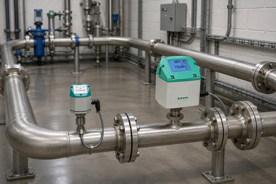
A compressed air consumption meter indicates:
1.250 Nm³/h
.
Does this automatically represent the consumption of the connected production hall?
Not necessarily in a branched or ring-shaped compressed air network.
In a conventional branch line, the flow direction is often clear:
Compressor → Main line → Consumer
In a ring main, however, compressed air can supply the same network section from different directions depending on the current operating condition.
For example, the flow may be:
left → right
in the morning and, a few minutes later:
right → left
.
For a reliable consumption balance, it is therefore not sufficient for the flow rate and pipe diameter alone to be correct.
Also decisive are:
- the actual flow direction,
- possible reverse flows,
- the position of the measuring point within the ring,
- the boundary of the consumer to be balanced,
- inlet and outlet conditions,
- the minimum and maximum flow rate,
- the reference standard used for standard volumetric flow,
- the correct processing of negative or reverse-direction flow rates.
The most important question is therefore not initially “Which flow meter do I need?”, but “Which compressed air quantity do I actually want to balance at this point?”
Suitable solutions can be found at ICS Schneider under Flow Measurement Technology and Consumption Meters for Gases and Compressed Air.
Table of Contents
- Why is measurement in a compressed air ring main more demanding?
- Why can the flow direction change?
- Correctly distinguishing flow rate and consumption
- Define the measurement objective first
- Selecting the correct measuring point in the ring main
- Clearly defining consumers and subnetworks
- Detecting and correctly evaluating reverse flow
- When is bidirectional flow measurement necessary?
- Detecting flow direction with a separate direction switch
- Creating a compressed air balance in a ring main
- Why a simple totalizer can produce incorrect consumption values
- Considering measuring range and low nighttime consumption
- Standardizing standard volume and reference conditions
- Correctly planning inlet and outlet straight runs
- Considering installation location and pipe condition
- Distinguishing dry and wet compressed air
- Detecting leaks using consumption measurements
- Transmitting measured values to PLC, control system and energy management
- Recommended planning and testing procedure
- Typical error patterns in ring mains
- Practical example: balancing a production hall in a compressed air ring main
- Suitable ICS products
- Conclusion
- FAQ
Why is measurement in a compressed air ring main more demanding?
Ring mains are used so that consumers can be supplied with compressed air from several directions.
In simplified form:
Compressor station → Ring → Consumer → Ring → Back to main line
This can:
- reduce pressure losses,
- shorten supply paths,
- distribute loads more evenly,
- supply individual areas more flexibly
.
However, this creates a measurement challenge
The flow in an individual section of a ring main does not necessarily have a constant direction.
Its direction depends on:
- which compressors are running,
- which consumers are active,
- which valves are open,
- which pressure losses are currently occurring in the network,
- whether subnetworks are connected or separated.
The same measuring point can therefore
temporarily detect an:
inflow
and, at another time, an:
outflow / reverse flow
.
Why can the flow direction change?
Compressed air generally flows according to the current pressure conditions in the network.
Example
A production hall is connected to a ring main at two points.
On the left side, the pressure is:
7,1 bar
.
On the right side:
6,9 bar
Initially
a larger proportion of the air flows:
left → hall
If a large consumer on the left side of the plant now starts
the pressure distribution can change.
The ring section may then suddenly be supplied from the opposite direction.
This reversal of flow is not necessarily a fault
but can be a normal consequence of:
- the ring-main structure,
- changing consumer load,
- compressor control
.
For the measurement, this means
A flow meter that correctly measures only one direction, or whose evaluation ignores reverse flow, can produce an incorrect balance in a ring-main section.
Correctly distinguishing flow rate and consumption
Two quantities are often confused in compressed air measurements.
Instantaneous flow rate
for example:
Q = 850 Nm³/h
Consumption
is, by contrast, the quantity integrated over time.
In simplified form:
V = ∫ Q(t) dt
At constant flow rate
in simplified form:
V = Q × t
Example
Q = 500 Nm³/h
for:
2 h
results in:
V = 1.000 Nm³
With changing flow direction
the sign becomes relevant.
For example:
+500 Nm³/h
for forward flow and:
-200 Nm³/h
for reverse flow.
Therefore
before evaluation it must be defined whether:
- only the net flow,
- forward and reverse quantities separately,
- or the total transported volumetric flow
is to be recorded.
Define the measurement objective first
The optimum measuring point depends directly on the question to be answered.
Typical measurement objectives include
- total consumption of a plant,
- consumption of a production hall,
- consumption of a machine,
- consumption of a cost center,
- balancing a section of the ring main,
- detecting leaks,
- optimizing compressors,
- monitoring network distribution.
Example
If the consumption of an individual machine is to be determined, a measuring point directly in its branch line is usually much clearer than a measurement in a main line of the ring network.
For a hall balance
several inflows and outflows may need to be recorded.
Therefore
The closer a measuring point is to the clearly defined consumer group, the easier it usually becomes to create a reliable consumption balance.
Selecting the correct measuring point in the ring main
A pipe that is technically easy to access is not automatically a good measuring point.
A suitable measuring point should
- clearly define the desired balance zone,
- provide suitable flow conditions,
- allow sufficient inlet and outlet straight runs,
- be accessible for installation and later calibration,
- avoid excessive condensate at the sensor,
- have a suitable pipe diameter.
Unfavorable position
A measuring point is selected somewhere in the ring simply because an unused connection is already available there.
Problem
The measured value may then simultaneously include:
- consumption of the desired hall,
- supply to a neighboring subnetwork,
- reverse flow from another ring section.
The result
may be a technically correct flow value, but possibly:
not the required consumption value
Clearly defining consumers and subnetworks
Before installation, a simplified piping diagram should therefore first be created.
The following should be marked
- compressors,
- compressed air receivers,
- ring mains,
- connecting lines,
- shut-off valves,
- major consumers,
- existing measuring points.
A balance boundary is then drawn
for example around:
Production Hall A
All lines crossing this boundary
must be taken into account for a complete balance.
If the hall has only one connection
the balance is simple:
Hall consumption = measured inflow
If it has two connections to the ring main
for example, the following must apply:
Hall consumption = Q1 + Q2
with both flow rates taken into account using the correct sign.
Detecting and correctly evaluating reverse flow
Reverse flow does not necessarily mean that compressed air flows back toward the compressors.
What is meant
is that the air flows at a particular measuring point opposite to the defined positive measuring direction.
Example
The sensor is defined for:
A → B = positive
However, the air temporarily flows
B → A
This means there is
negative or reverse-direction flow
.
This can occur, for example
- during load changes,
- after switching off a compressor,
- when a second compressor network is connected,
- when valve positions change,
- because of different consumers within the ring.
Before installation, it should therefore be checked
Can the flow direction reverse at this measuring point?
When is bidirectional flow measurement necessary?
Bidirectional measurement is particularly necessary if the actual flow can:
- occur in both directions
- and both directions are relevant for the balance.
Typical example
A measuring point is located directly in a:
ring main
rather than in a clearly directed consumer branch line.
The measuring system should then
not only detect:
|Q| = 300 Nm³/h
but, if possible, also:
Q = +300 Nm³/h
or:
Q = -300 Nm³/h
The IVA500 listed by ICS
is optionally available for:
bidirectional measurement
.
The IVA520
is also available in a bidirectional version according to the device data provided by ICS.
Important
The required directional function must be taken into account when ordering. A measuring point configured as standard for only one flow direction should not subsequently be interpreted automatically as a bidirectional consumption meter.
Detecting flow direction with a separate direction switch
For compressed air ring mains, ICS also offers the:
Its primary task is not
to measure actual consumption.
It detects
the flow direction
ICS describes the IVA 409 specifically for
compressed air and gas ring mains
According to ICS, the direction switch detects
even very small changes in flow direction and contains no mechanical wear parts.
The directional information
is provided via a potential-free contact.
In combination with consumption sensors
this makes it possible to distinguish between:
incoming compressed air
and:
outgoing compressed air
.
ICS explicitly specifies the combination
of the IVA 409 with:
IVA500 / IVA520
for measuring incoming and outgoing compressed air in ring mains.
Creating a compressed air balance in a ring main
A balance considers a defined system boundary.
In simplified form
Consumption = Sum of inflows − Sum of outflows
Example
A hall receives through the left line:
Q1 = +600 Nm³/h
and through the right line:
Q2 = +250 Nm³/h
The instantaneous total inflow is therefore
850 Nm³/h
If the network situation changes
and at measuring point 2:
-100 Nm³/h
now flows out of the balance zone, the result is:
600 − 100 = 500 Nm³/h
This makes it clear
When balancing a ring main, the sign of the flow is just as important as its magnitude.
Why a simple totalizer can produce incorrect consumption values
Many flow meters have an integrated consumption meter or totalizer.
In a line with a clearly defined flow direction
evaluation is simple:
Total consumption = Sum of all positive flows over time
When the direction reverses
it must be clearly defined how the device or higher-level software processes:
- forward quantity,
- reverse quantity,
- net consumption
.
For example, it would be problematic
if both:
+100 Nm³
and:
-100 Nm³
were simply added as:
100 Nm³ consumption
each.
The totalizer would then
indicate:
200 Nm³
although the net flow across the balance boundary is:
0 Nm³
.
Therefore, during commissioning it must already be defined
which quantity will subsequently be required:
Forward quantity / Reverse quantity / Net quantity
Considering measuring range and low nighttime consumption
A consumption measuring point must not only record the maximum production consumption.
For energy analyses, low flow rates are often particularly interesting
for example during:
- production shutdown,
- night operation,
- weekends,
- plant holidays.
The normal production flow may, for example, be
1.500 Nm³/h
.
At night, by contrast, only
60 Nm³/h
may remain.
These 60 Nm³/h
may partly result from:
- leaks,
- open blow-off nozzles,
- valve leakage,
- consumers that remain in operation
.
An excessively large measuring range
can reduce resolution in the lower range.
Therefore
during sizing:
Qmin
and:
Qmax
should be determined realistically.
Standardizing standard volume and reference conditions
Compressed air consumption is often specified as standard volume.
The indicated value
Nm³/h
does not simply refer to the geometric volume of the compressed air within the pipe.
Instead
the gas quantity is converted to defined reference conditions or, depending on the measuring principle, output as standard volumetric flow.
It is important
that different measuring points within the plant use the same reference conditions.
Otherwise
1.000 Nm³
at measuring point A cannot be directly compared with:
1.000 Nm³
at measuring point B if different reference conditions are configured.
With the IVA520
different reference conditions can be configured.
Therefore, during commissioning the following should be documented
- reference pressure,
- reference temperature,
- gas type used,
- unit used.
Particularly for energy management and cost-center allocation
All compressed air measuring points being compared should operate on the same defined reference basis.
Correctly planning inlet and outlet straight runs
Flow meters require suitable flow conditions.
Disturbances occur, for example, downstream of
- pipe bends,
- T-pieces,
- reducers,
- valves,
- control valves,
- filters.
These components can generate
- swirl,
- asymmetrical velocity profiles,
- turbulence
.
If the sensor is installed immediately downstream
the local flow profile may differ from the profile assumed for the measurement.
Therefore
the inlet and outlet conditions specified for the respective:
- sensor design,
- pipe size,
- upstream disturbance
must be observed.
Important
There is no universal inlet straight run that applies equally to every flow meter and every piping installation.
The specifications for the specific device are decisive.
Considering installation location and pipe condition
In addition to the flow direction, the mechanical conditions also play a role.
The following should be checked
- actual pipe internal diameter,
- nominal diameter,
- pipe material,
- corrosion and contamination,
- installation position,
- accessibility,
- operating pressure,
- gas temperature.
Especially with insertion sensors
the insertion depth must be set correctly.
An incorrect position of the sensing element
changes the locally measured flow velocity and can therefore cause a systematic error.
For large pipes
the actual internal diameter should therefore be known rather than using only the nominal DN value.
Distinguishing dry and wet compressed air
The measuring principle must match the condition of the compressed air.
Thermal consumption sensors
are particularly suitable for gaseous media without condensation on the sensing element.
A measuring point can be problematic
if:
- condensate is present,
- water droplets are entrained,
- the pipe regularly becomes wet.
For such applications
a correspondingly suitable measuring principle must be selected.
ICS offers, for example, the
IVD520 Inline Differential Pressure Flow Sensor
explicitly, among other applications, for:
wet compressed air
This illustrates
The question “ring main or branch line?” is only one selection criterion. The actual condition of the medium at the measuring point is equally important.
Detecting leaks using consumption measurements
One of the most important applications of compressed air meters is leak analysis.
Typical approach
The production area is observed outside regular operating hours.
Ideal condition
If all intended consumers are switched off, consumption should decrease significantly.
If, for example, a constant
Q = 120 Nm³/h
remains, it must be checked which consumers are causing this base consumption.
However, especially in a ring main
it must first be clarified whether these:
120 Nm³/h
are actually flowing into the area being investigated.
A ring section can also
supply compressed air to a neighboring area at night.
Therefore
for leak analysis, a clearly defined:
balance boundary
is more important than a single measured value somewhere in the ring.
Transmitting measured values to PLC, control system and energy management
For permanent consumption monitoring, measured values are often recorded centrally.
According to ICS, the IVA500 includes as standard
- 4 … 20 mA,
- pulse output,
- Modbus RTU via RS-485.
Depending on the version, the following are also available
- Modbus TCP,
- Ethernet,
- PoE,
- M-Bus.
For the IVA520
various analog and digital interface versions are also available.
Particularly important for ring mains
is not only the transmission of the flow magnitude.
The higher-level system should also know
- which flow direction is present,
- how positive and negative values are handled,
- which totalizer is being used.
For a clean balance
data point names should, for example, clearly distinguish between:
Flow Forward
Flow Reverse
Consumption Forward
Consumption Reverse
Net Consumption
Recommended planning and testing procedure for compressed air measurement in a ring main
- Define the measurement objective: Specify total consumption, hall consumption, machine consumption, leakage or network balance.
- Document the piping network: Record ring mains, branch lines, compressors and consumers.
- Define the balance boundary: Specify which lines enter or leave the desired consumption zone.
- Check possible flow directions: Determine for each measuring point whether reverse flow can occur.
- Select the measuring point: Combine the clearest possible consumer assignment with suitable pipe conditions.
- Check medium condition: Consider dry or wet compressed air, temperature, pressure and possible condensation.
- Estimate Qmin and Qmax: Consider production peaks as well as nighttime and leakage flows.
- Select the measuring principle: For dry compressed air, for example, use a thermal consumption sensor; for other conditions, evaluate appropriately suitable measuring principles.
- Define bidirectionality: If flow reversal is possible, select an appropriate device configuration.
- Define direction detection: If required, include IVA 409 or a suitable bidirectional measuring solution.
- Check pipe dimensions: Determine the actual internal diameter and installation conditions.
- Check inlet conditions: Consider bends, T-pieces, valves and reducers upstream of the measuring point.
- Define installation position: Observe the manufacturer’s installation specifications.
- Standardize reference conditions: Document reference temperature, reference pressure and gas type.
- Define signal processing: Clearly define forward, reverse and net quantities.
- Set up communication: Use analog signal, pulse, Modbus or another interface appropriate for the application.
- Plausibility-check the measuring point: After commissioning, compare the current flow direction with the system operating state.
- Check the consumption balance: Compare the sum of the sub-consumers with the main measurement.
- Analyze nighttime consumption: Evaluate base load and possible leakage flows.
- Store trends: Compare consumption across shifts, days and production conditions.
- Plan calibration: Include recurring verification or recalibration in the maintenance schedule.
Typical errors in compressed air measurement in ring mains
| Observation | Possible cause | Recommended check |
|---|---|---|
| Consumption of a hall appears negative at times | Flow direction in the ring has changed | Check flow direction and balance boundary |
| Flow value is correct, but consumption balance is not | Measuring point also records a neighboring network section | Check piping network and consumer assignment |
| Totalized consumption is unusually high | Forward and reverse flow are both added positively | Check totalizer configuration |
| Main meter indicates less than the sum of the sub-meters | Different reference conditions or measuring-point errors | Check standard conditions, gas type and installation |
| Flow changes significantly after a consumer elsewhere is switched on | Load distribution within the ring shifts | Analyze measuring direction and pressure distribution |
| Nighttime consumption is unexpectedly high | Leaks or supply to other ring sections | Check balance boundaries and operating conditions |
| Sensor shows unstable values immediately downstream of a pipe bend | Disturbed flow profile | Check installation position and required inlet straight run |
| Measured value no longer matches after piping modifications | Changed pipe geometry or flow distribution | Check internal diameter and measuring-point parameters |
| Thermal sensor provides implausible values when condensate occurs | Wet compressed air or liquid on the sensing element | Check medium condition and suitable measuring principle |
| Very small leakage flows are poorly resolved | Measuring range or pipe size too large | Reassess Qmin and measuring range |
| Reverse flow is not detected | Measuring system not designed for bidirectional detection | Check device version and direction detection |
Practical example: balancing a production hall in a compressed air ring main
A production hall is supplied from a central compressed air ring main at two points.
Measurement objective
The operator wants to record the:
actual compressed air consumption of the hall
.
Initial approach
A consumption sensor is installed in the left-hand main ring line.
Problem
The flow measured there does not exclusively supply the hall.
Depending on the operating condition, part of the air continues to flow into the:
remaining ring
The measuring point is therefore unsuitable for hall consumption accounting
even though the sensor itself measures correctly.
Improved solution
The balance boundary is placed directly around the hall.
At connection A
the following is measured:
QA
At connection B
the following is measured:
QB
Both measuring points can change direction depending on the network situation
and are therefore evaluated according to direction.
Snapshot 1
QA = +480 Nm³/h
QB = +220 Nm³/h
Hall consumption
QHalle = 700 Nm³/h
Snapshot 2
After a change in the ring-main load:
QA = +520 Nm³/h
QB = -80 Nm³/h
The net inflow is then
QHalle = 520 − 80 = 440 Nm³/h
The negative flow at measuring point B
is not a measurement error.
It shows that part of the compressed air supplied through connection A is currently flowing back into the ring through connection B.
Result
Only the combination of suitable measuring-point selection and correct directional evaluation turns multiple flow values into a reliable consumption balance.
Suitable ICS products for compressed air ring mains
IVA500 – Consumption Sensor for Compressed Air and Gases
For consumption measurement in existing pipelines, ICS offers the:
ICS specifies, among other things
- measurement of mass flow with direct output of standard volumetric flow,
- thermal mass-flow measuring principle,
- use for compressed air and various non-corrosive gases,
- 4 … 20 mA, pulse and Modbus RTU as standard,
- additional communication interfaces optionally available,
- integrated display,
- use from DN15 to DN1000, larger diameters on request,
- installation via ½” ball valve,
- optional bidirectional measurement.
Particularly important for ring mains
is the option:
bidirectional measurement
because the flow direction can change within a section of the ring.
IVA520 – Inline Flow and Consumption Sensor
For a defined inline measuring section, ICS offers the:
IVA520
.
The IVA520
measures mass flow and directly outputs the standard volumetric flow.
ICS specifies, among other things
- measurement of flow and consumption,
- thermal measuring principle,
- integrated measuring section,
- various measuring ranges,
- various reference standards,
- 4 … 20 mA,
- pulse output,
- Modbus RTU,
- additional interface variants,
- optional bidirectional measurement.
For a new installation
the integrated measuring section can help clearly define the mechanical installation of the consumption measurement.
IVA 409 – Direction Switch for Compressed Air and Gas Systems
Especially for ring mains, ICS offers the:
Its central task
is detection of the:
flow direction of compressed air and gases
ICS specifies
- special suitability for ring mains,
- detection of very small changes in flow direction,
- no mechanical wear parts,
- installation under pressure,
- potential-free contact for directional information.
Particularly relevant
is the combination described by ICS with:
IVA500 / IVA520
for clear detection of:
incoming and outgoing compressed air
in ring mains.
IVD520 – for Wet Compressed Air
If wet compressed air is expected at the intended measuring point, ICS also offers the:
IVD520 Inline Differential Pressure Flow Sensor
ICS explicitly lists the application
wet compressed air
The instrument provides
- flow rate,
- total consumption,
- temperature,
- pressure.
Which solution is suitable?
| Task | Suitable ICS solution |
|---|---|
| Consumption measurement in an existing compressed air line | IVA500 |
| Consumption measurement with a defined inline measuring section | IVA520 |
| Bidirectional operation in a ring main | IVA500 or IVA520 in the corresponding bidirectional version |
| Separate detection of flow direction in a ring main | IVA 409 |
| Measurement of incoming and outgoing compressed air in ring mains | IVA 409 in combination with IVA500 / IVA520 according to the measuring concept |
| Wet compressed air | IVD520 or evaluate a measuring principle suitable for the specific application |
Additional solutions can be found under Flow Measurement Technology at ICS Schneider.
Conclusion
Compressed air measurement in a ring main is primarily a question of the:
correct balance boundary
and only then a question of the sensor.
A ring main can change its flow direction
Depending on consumers, compressors and pressure distribution, the same pipe can temporarily carry flow in both directions.
A single measuring point is therefore not automatically a consumption meter
The measured flow must be clearly assignable to the required:
- consumer,
- subnetwork,
- building,
- cost center
.
With reverse flow, the direction must be taken into account
For a net balance:
Inflow positive → Reverse flow negative
Bidirectional measurement can therefore be decisive
IVA500 and IVA520 are available from ICS with a corresponding bidirectional option.
For ring mains, the IVA 409 can additionally be used
to clearly detect the current flow direction.
The measuring point itself also determines measurement quality
Inlet conditions, pipe internal diameter, insertion depth, medium condition and reference conditions must match the measuring concept.
And finally
all meters within a balance must use the same definition of:
Standard volume + Flow direction + Totalization
.
For practical applications
Document the piping network → Define measurement objective → Define balance boundary → Identify all inflows and outflows → Check possible flow reversal → Select suitable measuring points → Determine Qmin and Qmax → Check compressed air condition → Select suitable measuring principle → If required, provide bidirectional measurement or IVA 409 → Check inlet conditions and pipe data → Configure uniform reference conditions → Clearly evaluate forward and reverse flow → Check totalizer → Test measuring points under different system operating conditions → Analyze nighttime consumption and leaks → Permanently document consumption trends.
FAQ: Correctly Measuring Compressed Air Consumption in a Ring Main
Why is flow measurement in a ring main difficult?
Because compressed air can flow through a network section in different directions depending on the current pressure and consumption situation.
Can the flow direction in a compressed air ring main actually reverse?
Yes. Changes in consumer load, compressor control or valve positions can change the pressure distribution and therefore the local flow direction.
What is the difference between flow rate and consumption?
Flow rate is the quantity of gas currently transported per unit of time. Consumption is the gas quantity integrated over a period of time.
How is compressed air consumption calculated?
In principle, the flow rate is integrated over time: V = ∫ Q(t) dt.
What does bidirectional flow measurement mean?
A bidirectional measuring system can detect flow in both possible directions or evaluate it according to direction.
When do I need bidirectional compressed air measurement?
When the flow direction at the measuring point can change and both directions are relevant for the consumption or network balance.
Do I also need bidirectional measurement in a branch line?
Not necessarily. If the flow is clearly directed from the ring toward the consumer by design and reverse flow is not possible, a correspondingly directional measurement is generally sufficient.
Where should a compressed air meter be installed?
Preferably where the desired consumer or balance area can be clearly defined and suitable flow and installation conditions are available at the same time.
Can I measure the consumption of a hall directly in the ring?
Only if the measuring point, or combination of several measuring points, actually records all inflows and outflows of the hall.
What does a balance boundary mean?
A balance boundary is an imaginary boundary around the area being analyzed. All compressed air lines crossing this boundary must be included in a complete balance.
How is a hall balance calculated with two compressed air connections?
The direction-dependent flow rates of both connections are added using their respective signs.
Can a negative flow value be correct?
Yes. At a bidirectional measuring point, a negative value can simply mean that the current flow is opposite to the defined positive direction.
Is reverse flow a fault in a compressed air network?
Not necessarily. In ring mains, a reversal of flow can be completely normal due to the current pressure distribution.
Why can a totalizer be misinterpreted in a ring main?
If forward and reverse quantities are not processed according to the measurement objective, the total transported quantity can, for example, be confused with the actual net consumption.
What is the difference between gross quantity and net quantity?
A gross evaluation can consider all transported quantities regardless of direction. The net quantity, by contrast, considers inflow and reverse flow with different signs.
Why is nighttime consumption important?
During production shutdowns, remaining flow rates can indicate leaks or unintentionally active consumers.
Can I detect leaks using a main meter?
A main meter can reveal an unusual base consumption. To locate the leak, further sub-metering or systematic leak detection is then required.
Why is the minimum flow important when selecting a device?
A measuring instrument must not only record production peaks but, where required, also sufficiently detect low nighttime and leakage flows.
What is standard volumetric flow?
Standard volumetric flow describes the gas quantity referenced to defined reference conditions for pressure and temperature.
Why must the reference conditions of all compressed air meters be the same?
Only then can consumption values from different measuring points be directly compared and balanced.
What are inlet straight runs?
Inlet straight runs are sufficiently long pipe sections upstream of the flow meter in which a flow profile suitable for measurement can develop.
Why are pipe bends upstream of the sensor problematic?
They can generate swirl and asymmetrical velocity profiles and thereby influence the flow measurement.
How long must the inlet straight run be?
This depends on the specific measuring instrument, pipe dimension and type of upstream disturbance. The manufacturer’s specifications for the respective sensor are decisive.
Why must the pipe internal diameter be known?
For certain flow measurement methods, it is required to calculate the volumetric flow or correctly configure the instrument.
Can I use a thermal consumption sensor with wet compressed air?
The specific suitability depends on the sensor and process conditions. Condensation on the thermal sensing element can be problematic. For wet compressed air, ICS offers suitable differential-pressure flow solutions such as the IVD520.
What is the IVA500?
The IVA500 is a consumption sensor listed by ICS for compressed air and various gases based on the thermal mass-flow measuring principle.
Can the IVA500 measure bidirectionally?
Yes. ICS lists optional bidirectional measurement for the IVA500.
For which pipe sizes is the IVA500 suitable?
ICS specifies use from DN15 to DN1000; larger diameters are available on request.
Which interfaces does the IVA500 have?
ICS specifies 4 … 20 mA, pulse output and Modbus RTU via RS-485 as standard, as well as additional optional interfaces.
What is the IVA520?
The IVA520 is an inline flow and consumption sensor with an integrated measuring section for compressed air and various gases.
Can the IVA520 measure bidirectionally?
Yes. A bidirectional version is provided for in the device data made available by ICS.
What is the IVA 409?
The IVA 409 is a direction switch for compressed air and gas systems that ICS specifically offers for detecting flow direction in ring mains.
Does the IVA 409 itself measure compressed air consumption?
Its primary task is to detect the flow direction. For actual consumption measurement, it is combined with suitable consumption sensors.
Can the IVA 409 be combined with IVA500 or IVA520?
Yes. ICS explicitly describes the combination for measuring incoming and outgoing compressed air in ring mains.
What is the IVD520?
The IVD520 is an inline differential-pressure flow sensor that ICS offers, among other applications, for wet compressed air and technical gases.
Which values does the IVD520 provide?
ICS specifies flow rate, total consumption, temperature and pressure.
Which measuring solution is most suitable for a compressed air ring main?
This depends on the measurement objective and installation conditions. If flow reversal is possible, a suitable bidirectional IVA500/IVA520 version or a measuring concept with IVA 409 is particularly relevant.
Where can I find the IVA500 at ICS Schneider?
Further information can be found under IVA500 Consumption Sensor at ICS Schneider.
Where can I find the IVA 409 at ICS Schneider?
Further information can be found under IVA 409 Direction Switch at ICS Schneider.
Where can I find the IVD520 at ICS Schneider?
Further information can be found under IVD520 Inline Differential Pressure Flow Sensor at ICS Schneider.
Where can I find additional compressed air consumption meters at ICS Schneider?
An overview can be found under Consumption Meters for Gases and Compressed Air at ICS Schneider.
Where can I find additional flow measurement instruments at ICS Schneider?
An overview can be found under Flow Measurement Technology at ICS Schneider.