


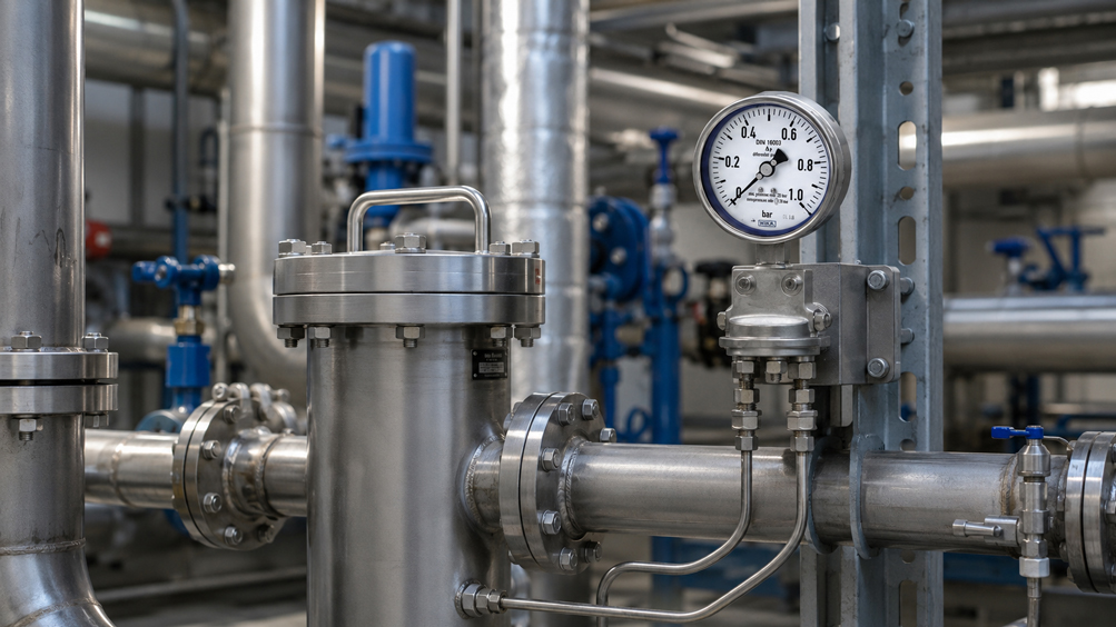
A filter operates in a process line at:
25 bar operating pressure
.
However, only:
0 … 250 mbar differential pressure
is to be measured across the filter.
At first glance, a differential pressure gauge with:
0 … 250 mbar
therefore appears sufficient.
However, this is only one part of the sizing process.
While the measuring instrument is intended to indicate only the difference between the high-pressure and low-pressure sides, both process connections are simultaneously subjected to a significantly higher operating pressure.
For example:
p+ = 25,20 bar
and:
p- = 24,95 bar
.
The differential pressure is:
Δp = p+ − p- = 0,25 bar = 250 mbar
At the same time, the measuring system is exposed to approximately:
25 bar static pressure
.
A differential pressure gauge must therefore always be selected for at least two different loads:
- the differential pressure that actually needs to be measured,
- the maximum possible static or common operating pressure.
In addition, it must be determined which:
- single-sided overload,
- two-sided overload,
- alternating differential pressure overload,
- pressure spikes
can occur during operation or during startup, shutdown and valve operation.
A small measuring range therefore does not automatically mean that the instrument is suitable only for low process pressures. Conversely, a high permissible static pressure does not automatically mean that every possible single-sided overload condition is permissible.
Suitable instruments can be found at ICS Schneider under Pressure Measurement Technology and under Differential Pressure Gauges.
Table of Contents
- What does a differential pressure gauge measure?
- What does static pressure mean?
- Understanding small differential pressures at high operating pressure
- Which pressure values must be specified when selecting an instrument?
- Distinguishing differential pressure measuring range and overload safety
- Why single-sided overload is particularly critical
- Considering pressure spikes and rapid pressure changes
- Selecting the measuring principle to suit the application
- Correctly sizing the differential pressure measuring range
- Correctly evaluating the zero point
- Influence of static pressure on the indication
- Why a valve manifold is useful
- Avoiding errors when operating valves
- Considering impulse lines and height differences
- Filter monitoring using differential pressure
- Pump monitoring using differential pressure
- Level measurement in closed vessels
- When switch contacts are useful
- When an electrical output signal is useful
- Recommended selection and testing procedure
- Typical error patterns
- Practical example: monitoring a filter at 25 bar operating pressure
- Suitable ICS products
- Conclusion
- FAQ
What does a differential pressure gauge measure?
A differential pressure gauge has two pressure connections.
Typically:
p+
for the high-pressure side and:
p-
for the low-pressure side.
The indicated measurand is
Δp = p+ − p-
Example
p+ = 18,40 bar
p- = 18,15 bar
This results in
Δp = 0,25 bar = 250 mbar
The pressure gauge therefore does not need to
0 … 20 bar
indicate.
For the actual measurement task, for example:
0 … 400 mbar
may be sufficient.
Mechanically, however, the instrument must still
safely withstand the high pressure at both process connections.
What does static pressure mean?
In differential pressure measurement, the terms:
static pressure
or:
operating pressure
are frequently used.
In simplified terms, this means
the high common pressure level at which the small differential pressure measurement takes place.
As an approximation, it can be considered as
pstat ≈ (p+ + p-) / 2
Example
p+ = 100,20 bar
p- = 100,00 bar
The result is
Δp = 0,20 bar
while the common pressure is approximately:
pstat = 100,10 bar
.
The ratio is remarkable
The differential pressure here is only around:
0,2 %
of the common pressure level.
This is precisely why
differential pressure measurements at high static pressure are technically demanding.
Understanding small differential pressures at high operating pressure
A typical application is filter monitoring.
Upstream of a filter
the pressure is:
p1 = 30,18 bar
Downstream of the filter
the pressure is:
p2 = 30,03 bar
The required value is not the line pressure
but the pressure loss across the filter:
Δp = 150 mbar
A suitable differential pressure gauge
could therefore, for example, have a measuring range of:
0 … 250 mbar
.
However
the measuring system must simultaneously be designed for at least the:
static operating pressure ≥ 30 bar
that occurs.
In addition, it must be considered
what happens if:
- an impulse line is shut off,
- one side is pressurized first,
- a valve closes abruptly,
- the filter becomes completely blocked,
- one side becomes depressurized.
Which pressure values must be specified when selecting an instrument?
For reliable sizing, information such as:
Measuring range 0 … 250 mbar
is not sufficient.
At least the following should be known
- required differential pressure measuring range,
- normal static operating pressure,
- maximum possible operating pressure,
- maximum possible single-sided differential pressure,
- possible pressure spikes,
- medium,
- temperature,
- process connection,
- required materials.
For critical applications, additionally
- rate of pressure change,
- pulsations,
- vibrations,
- Ex requirements,
- required switch contacts,
- electrical output signal.
A meaningful inquiry would therefore be, for example
Δp 0 … 250 mbar / operating pressure 35 bar / maximum 40 bar / water / 80 °C
and not simply:
Pressure gauge 250 mbar
Distinguishing differential pressure measuring range and overload safety
The differential pressure measuring range describes the range in which the instrument is intended to measure and indicate.
Example
0 … 160 mbar
Overload safety, by contrast, describes
which higher pressure load the measuring system can withstand without unacceptable damage.
These values can differ significantly
A highly overload-resistant differential pressure gauge can, for example:
0 … 60 mbar
indicate while simultaneously being designed for substantially higher operating and overload pressures.
Therefore
Measuring range ≠ permissible static pressure ≠ overload limit
All three values
must be checked separately.
Why single-sided overload is particularly critical
During normal operation, both sides of a differential pressure gauge are often at almost the same pressure level.
For example
p+ = 40,15 bar
p- = 40,00 bar
The load caused by the differential pressure is then only
150 mbar
The situation becomes critical
if one side suddenly becomes depressurized.
Example
p+ = 40 bar
p- = 0 bar
This results in
Δp = 40 bar
For a measuring range of 0 … 250 mbar, this corresponds to
the:
160-fold full-scale value
Such a load can occur, for example, due to
- incorrect valve operation,
- leaking or blocked impulse line,
- single-sided pressurization during startup,
- single-sided venting,
- maintenance work.
It is therefore particularly important
The statement “suitable for 40 bar static pressure” must not be equated, without verification, with “can withstand any single-sided overload up to 40 bar.”
The specific single-sided, two-sided and alternating overload safety must be taken from the technical data for the respective instrument version.
Considering pressure spikes and rapid pressure changes
In addition to steady operating pressure, dynamic pressure events can occur.
Typical causes
- rapid opening or closing of valves,
- pump startup,
- pump shutdown,
- pressure surges,
- pulsations,
- switching between process lines.
As a result, very high
short-term:
Δp peaks
can occur.
These do not have to last long
to mechanically stress a sensitive measuring element.
With WIKA high-pressure differential pressure gauges
such as DPGT43HP or DPGS43HP, liquid damping of the measuring cell is therefore used to stabilize the indication at high rates of pressure change.
Important
Damping does not replace the required:
mechanical overload resistance
Selecting the measuring principle to suit the application
Differential pressure gauges can operate with different measuring systems.
Diaphragm measuring systems
are particularly suitable for:
- small differential pressures,
- high static pressures,
- process applications
.
In highly overload-resistant versions
the measuring element can be mechanically supported by design so that its deflection is mechanically limited in the event of overload.
Magnetic piston systems
such as the WIKA 700.01, by contrast, are compact and are suitable, among other things, for:
- filter monitoring,
- pump monitoring,
- gas and air supply,
- piping systems.
For liquids
depending on the application, for example, the 700.02 version with magnetic piston and separating diaphragm may be suitable.
Selection should therefore not be based exclusively on the
measuring range
.
Correctly sizing the differential pressure measuring range
A measuring range that is as small as possible generally improves the readability of small pressure differences.
However
the measuring range must also cover the actual possible operating range.
Example
Normal filter condition:
Δp = 40 … 100 mbar
Filter replacement at
Δp = 180 mbar
Maximum expected
Δp = 220 mbar
A range of
0 … 250 mbar
may be more suitable here than:
0 … 100 mbar
Because
although the smaller range would provide better resolution during normal operation, it would regularly be outside the intended measuring range under actual process conditions.
Conversely
a range of:
0 … 10 bar
would be of little use for a typical differential pressure of 100 mbar.
Basic rule
The measuring range should match the actual differential pressure task – static pressure resistance is selected separately from it.
Correctly evaluating the zero point
When:
p+ = p-
theoretically:
Δp = 0
The instrument should then
within its permissible error limits:
0
indicate.
In practice, however, a distinction must be made between
zero point with the instrument depressurized
and:
zero point with static pressure applied to both sides
Example
A pressure gauge indicates exactly zero at:
p+ = p- = 0 bar
.
In the process, both sides are subsequently exposed to
30 bar
Even if the differential pressure is still zero
the static pressure can influence the indication depending on the measuring system used.
Therefore
for applications with particularly small differential pressures, the following should be checked:
- what influence of static pressure is specified,
- how the manufacturer specifies zero-point checking,
- whether zero-point correction is provided,
- under which conditions this may be carried out.
Important
A zero-point error should not simply be adjusted before it has been clarified whether the cause actually lies in the instrument or in the measuring point.
Influence of static pressure on the indication
With very small differential pressure measuring ranges, the influence of the common pressure can become relevant.
The data sheet for WIKA types 732.31, 733.31, 732.51 and 733.51
for example, specifies a separate characteristic for:
influence of static pressure
.
For small spans up to 0,25 bar
it specifies:
±0,3 % per 1 bar static pressure
relative to the respective full-scale value.
For spans above 0,25 bar
it specifies:
±0,04 % per 1 bar static pressure
This demonstrates an important relationship
The smaller the differential pressure to be measured in relation to the common pressure, the more important this influence becomes when evaluating measurement uncertainty.
Therefore, the statement
Instrument is statically pressure-resistant up to 40 bar
is not sufficient for an accuracy assessment.
An additional question must be asked
How does static pressure affect the measurement error?
Why a valve manifold is useful
A valve manifold is often installed between the process and the differential pressure gauge.
Typical functions include
- isolating the high-pressure side,
- isolating the low-pressure side,
- connecting or equalizing both sides,
- venting or testing, depending on the version.
An equalizing valve enables
under suitable conditions:
p+ = p-
This can enable
a zero-point check of the measuring chain without depressurizing the entire process.
In addition
a valve manifold can facilitate removal and maintenance of the measuring instrument.
However
A valve manifold protects against incorrect loading only if its circuit and operation are suitable for the specific measuring point.
Avoiding errors when operating valves
With a small differential pressure measuring range and high operating pressure, an incorrect valve sequence can produce a very high single-sided load.
Example
Measuring range:
0 … 100 mbar
Operating pressure:
100 bar
If one side is
depressurized during maintenance while:
100 bar
continues to be applied to the other side, a short-term differential pressure load of:
100 bar
is created.
This corresponds to
1.000 × full-scale value
Therefore
startup, shutdown, zero-checking and venting procedures should be defined in accordance with:
- the instrument instructions,
- the valve manifold design,
- the system documentation
.
In particular, it should not generally be assumed
that venting one side under full operating pressure is permissible for every differential pressure measuring instrument.
Considering impulse lines and height differences
An incorrect zero point does not necessarily have to be caused by the pressure gauge itself.
With liquid media
different liquid columns in the two impulse lines can produce a hydrostatic differential pressure.
In simplified form
Δph = ρ × g × Δh
Where
ρ= density of the medium,g= gravitational acceleration,Δh= height difference.
For water
a height difference of approximately:
1 m
already corresponds to a hydrostatic pressure of approximately:
98 mbar
With a measuring range of
0 … 160 mbar
this influence would be considerable.
Therefore, among other things
- routing of the impulse lines,
- fill condition,
- air pockets,
- condensate,
- height differences
must be taken into account.
Important
Before carrying out zero-point correction, it should therefore always be checked whether the measuring point itself produces a real hydrostatic differential pressure.
Filter monitoring using differential pressure
One of the most common applications is condition monitoring of filters.
The measured value is
ΔpFilter = pupstream of filter − pdownstream of filter
As contamination increases
the pressure loss normally rises.
Example
New filter:
50 mbar
Normal operation
50 … 150 mbar
Maintenance limit
200 mbar
At the same time, the line pressure can be
30 bar
.
The instrument must therefore
on the one hand provide good resolution in the small range:
0 … 250 mbar
and on the other hand withstand the high static process pressure.
Pump monitoring using differential pressure
Pumps can also be monitored using a pressure difference.
For example
Δp = pdischarge side − psuction side
This can provide indications of
- pump operation,
- pumping condition,
- unusual operating conditions.
In this case, however, the differential pressure can
be considerably greater than in filter monitoring.
Therefore
the measuring range should be selected according to the actual pump characteristics rather than automatically using an especially small differential pressure range.
Level measurement in closed vessels
Differential pressure can also be used for level measurement in closed vessels.
Principle
At the bottom of the vessel:
gas pressure + hydrostatic pressure
acts.
At the top
essentially:
gas pressure
acts.
The difference is therefore
in simplified form:
Δp = ρ × g × h
The gas pressure can, for example, be
20 bar
while the hydrostatic measuring range is only:
0 … 500 mbar
.
Here too, the combination of
the:
small Δp + high static pressure
is decisive.
When switch contacts are useful
For filter or pump monitoring, local indication alone is often not sufficient.
In addition, the following may be required
Limit reached → Switching signal
Example
Δp ≥ 200 mbar → Filter replacement signal
For this purpose, ICS offers, for example
the:
WIKA types DPGS43HP.100 and DPGS43HP.160
ICS specifies
- differential pressure measuring ranges from 0 … 60 mbar,
- high static operating pressure,
- high overload safety up to 40, 100, 250 or 400 bar,
- inductive contacts for hazardous areas,
- switch contacts for PLC applications.
This allows
local indication and switching function to be combined in one instrument.
When an electrical output signal is useful
For continuous transmission to:
- PLC,
- control system,
- data logger,
- remote monitoring
an analog output signal is useful.
A corresponding solution is the
ICS specifies the following output signals, among others
4 … 20 mA
0 … 20 mA
and:
0 … 10 V
This simultaneously provides
a:
mechanical local indication
and:
electrical process value transmission
.
Recommended selection and testing procedure
- Define the measurement task: Specify filter, pump, vessel, flow or another differential pressure application.
- Determine the normal differential pressure: Establish the typical operating range.
- Determine the maximum differential pressure: Consider contamination, blockage and other process conditions.
- Select the measuring range: Combine sufficient resolution with adequate reserve.
- Determine the normal static pressure: Establish the common process pressure level.
- Determine the maximum operating pressure: Include all possible system conditions.
- Analyze single-sided overload: Check whether one side can become depressurized while full operating pressure remains on the other.
- Consider pressure spikes: Analyze valves, pumps and rapid switching operations.
- Select the measuring principle: Determine whether a diaphragm, magnetic piston or another suitable design is required.
- Check the medium: Consider gas or liquid, corrosiveness, viscosity and crystallization.
- Define materials: Select wetted parts to suit the application.
- Check temperature: Consider process and ambient temperature.
- Evaluate the influence of static pressure: Especially for small differential pressure measuring ranges.
- Plan the valve manifold: Provide isolation, pressure equalization and, if required, test facilities.
- Plan impulse lines: Consider elevations, condensate and possible air pockets.
- Define the mounting position: Observe the manufacturer’s specifications.
- Check the zero point before commissioning: Check the instrument under defined conditions.
- Start up according to the measuring-point concept: Avoid impermissible single-sided overload.
- Plausibility-check the zero point under operating conditions: Where technically provided.
- Compare the measured value with the process condition: Check plausibility.
- Check switch contacts or output signal: If provided.
- Document overload cases: Define permissible process conditions and valve operation.
- Plan recurring inspections: Include zero point, function and, where applicable, calibration in the maintenance plan.
Typical errors with differential pressure gauges under high static pressure
| Observation | Possible cause | Recommended check |
|---|---|---|
| Pressure gauge was damaged despite low Δp | Static pressure or single-sided overload too high | Check operating pressure and overload safety |
| Pointer remains off zero after maintenance | Single-sided overload during valve operation | Check valve sequence and zero point |
| Zero point is correct when depressurized but not during operation | Influence of static pressure or measuring-point error | Check manufacturer specification and impulse lines |
| Indication jumps when valve is opened | Rapid pressure change or pressure surge | Check startup procedure and damping |
| Filter differential pressure appears unusually high | Impulse line blocked or valve not fully open | Check measuring lines and valve manifold |
| Filter differential pressure appears too low | Equalizing valve not completely closed | Check valve manifold |
| Constant zero-point offset with liquid | Different liquid columns | Check height difference and impulse lines |
| Indication drifts after venting | Air pocket or unevenly filled lines | Check measuring lines correctly |
| Pointer regularly hits the end stop | Measuring range too small or process peaks | Analyze maximum Δp and overload condition |
| Indication is stable but systematically offset | Influence of static pressure | Include data-sheet specification in accuracy assessment |
| Switch contact trips too early or too late | Zero point, switching point or measuring range unsuitable | Check mechanical measured value and contact separately |
Practical example: monitoring a filter at 25 bar operating pressure
The contamination condition of a filter in a process line is to be monitored.
Process data
Operating pressure:
25 bar
Differential pressure with a clean filter
40 mbar
Normal operating range
40 … 150 mbar
Filter replacement limit
200 mbar
Maximum expected differential pressure
230 mbar
Step 1: Measuring range
A range of:
0 … 250 mbar
offers significantly better readability than, for example:
0 … 10 bar
Step 2: Static pressure
At the same time, the differential pressure gauge must be suitable for at least:
25 bar operating pressure
.
Step 3: Maximum process pressure
The actual maximum line pressure is checked.
Assume:
pmax = 32 bar
Then
the selected pressure rating must be sufficiently above this value.
Step 4: Overload condition
Consider what happens if an impulse line becomes depressurized during maintenance work.
In that case, theoretically
almost the full operating pressure could act on the differential pressure measuring system from one side.
Therefore
an instrument is selected whose documented overload safety matches the actual measuring point.
Step 5: Zero point
With equalized pressure:
p+ = p-
the zero point is checked in accordance with the instrument and system instructions.
Step 6: Maintenance limit
If only local indication is required, a suitable mechanical differential pressure gauge is sufficient.
If an automatic signal is required at
Δp ≥ 200 mbar
a version with switch contacts may be suitable, for example.
If the complete filter trend is to be recorded
a differential pressure gauge with electrical output signal is particularly suitable.
Result
The correct instrument selection is not based on “0 … 250 mbar” alone, but on the combination of differential pressure measuring range, 25-bar operating pressure, maximum process pressure, overload scenario, medium and required signal function.
Suitable ICS products for differential pressure at high static pressure
WIKA types 732.31, 733.31, 732.51 and 733.51
For small differential pressures at comparatively high process pressure, ICS offers the:
WIKA types 732.31, 733.31, 732.51 and 733.51
ICS specifies, among other things
- differential pressure measuring ranges from 0 … 16 mbar to 0 … 40 bar,
- high operating or static pressure up to 40 bar,
- overload safety up to 40 bar,
- fully welded wetted chamber,
- safety version S3 according to EN 837 for types 732.31 and 733.31.
Typical applications
include:
- pump monitoring,
- filter monitoring,
- process industry.
Particularly interesting
is the combination of:
small Δp measuring range + high static operating pressure
For high accuracy requirements
the influence of static pressure specified in the data sheet should additionally be taken into account.
WIKA DPGT43HP – Differential Pressure Gauge with Output Signal
For applications with high operating pressure and additional electrical signal transmission, ICS offers the:
ICS specifies
- differential pressure measuring ranges from 0 … 60 mbar,
- operating or static pressure optionally up to 40, 100, 250 or 400 bar,
- correspondingly high overload safety,
- liquid damping of the measuring cell for high rates of pressure change,
- output signals for process value transmission.
The instrument is particularly suitable
when the following are required:
local indication + electrical remote transmission
WIKA DPGS43HP – Differential Pressure Gauge with Switch Contacts
For limit monitoring, ICS offers the:
WIKA types DPGS43HP.100 and DPGS43HP.160
ICS specifies
- differential pressure measuring ranges from 0 … 60 mbar,
- high static pressure and overload safety up to 40, 100, 250 or 400 bar,
- liquid damping of the measuring cell,
- inductive contacts,
- switch contacts for PLC applications.
Typical task
Indicate filter pressure loss + switch limit value
WIKA types 732.14 and 762.14
For particularly high operating pressures, ICS also offers the:
ICS specifies
- display ranges up to 0 … 40 bar,
- high static pressure and overload safety optionally 40, 100, 250, 400 or 650 bar,
- transmission fluid for damping at high rates of pressure change,
- stainless-steel version or special materials.
This makes this series particularly interesting
when the common pressure level is significantly above conventional 40-bar applications.
WIKA types 700.01 and 700.02
For compact monitoring tasks, ICS also offers the:
ICS specifies
- type 700.01: measuring ranges from 0 … 400 mbar to 0 … 10 bar,
- type 700.02: measuring ranges from 0 … 160 mbar to 0 … 2,5 bar,
- static pressures for type 700.01 optionally up to 100, 250 or 400 bar,
- type 700.02 up to a maximum of 100 bar,
- high single-sided, two-sided and alternating overload capability depending on the respective version,
- optional reed contacts.
Typical applications according to ICS
- filter systems,
- pump monitoring,
- cooling circuits,
- piping systems.
Which solution is suitable?
| Application | Suitable ICS solution |
|---|---|
| Very small differential pressure from 16 mbar at static pressure up to 40 bar | WIKA 732.31 / 733.31 / 732.51 / 733.51 |
| Small differential pressure at high static pressure up to 400 bar with electrical output | WIKA DPGT43HP |
| Small differential pressure at high static pressure with limit contacts | WIKA DPGS43HP |
| Process application with static pressure up to 650 bar | WIKA 732.14 / 762.14 |
| Compact filter or pump monitoring at high operating pressure | WIKA 700.01 / 700.02 according to medium and pressure rating |
Additional instruments can be found under Differential Pressure Gauges at ICS Schneider.
Conclusion
When measuring differential pressure under high operating pressure, two completely different pressure quantities must be handled simultaneously:
small differential pressure + high static pressure
The measuring range describes only the actual differential pressure
For example:
0 … 250 mbar
At the same time, the measuring system can be exposed to an operating pressure of
25 bar, 100 bar or more
.
Overload safety is a separate instrument characteristic
Single-sided loads are particularly critical during:
- startup,
- shutdown,
- venting,
- isolation,
- maintenance.
The zero point must also be interpreted correctly
A zero point at:
0 bar / 0 bar
is not automatically completely identical to the behavior at:
40 bar / 40 bar
Static pressure can influence measurement accuracy
and should be taken into account particularly for very small differential pressure measuring ranges.
A valve manifold supports operation and testing
but incorrect valve operation can cause extreme single-sided overload, particularly with small measuring ranges.
For practical applications
Define the measurement task → determine normal and maximum differential pressure → establish static operating pressure → check maximum process pressure → analyze single-sided overload cases → consider pressure spikes → select a suitable measuring principle → size the measuring range → check materials and medium → evaluate the influence of static pressure → plan valve manifold and impulse lines → check the zero point correctly → define startup and maintenance procedures → plausibility-check the measured value under operating conditions → plan recurring inspections.
FAQ: Differential Pressure Gauges at High Static Pressure
What does a differential pressure gauge measure?
It measures the difference between two process pressures according to Δp = p+ − p-.
What is static pressure in differential pressure measurement?
It refers to the common operating pressure level at which the much smaller differential pressure measurement takes place.
Can I measure 100 mbar differential pressure at 40 bar line pressure?
Yes, provided that the differential pressure measuring instrument used is suitable both for the required small measuring range and for at least the static pressure that occurs and the possible overload conditions.
Which is more important: measuring range or static pressure?
Both. The measuring range determines the actual differential pressure measurement, while the permissible static pressure rating determines the common process pressure to which the measuring system may be exposed.
Is static pressure the same as differential pressure?
No. With 30,2 bar on the high-pressure side and 30,0 bar on the low-pressure side, the differential pressure is only 0,2 bar even though the instrument operates under approximately 30 bar static pressure.
What does single-sided overload mean?
One side of the differential pressure measuring system is subjected to high pressure while a significantly lower pressure is present on the other side.
Why can single-sided overload be dangerous?
Because this can create a differential pressure many times greater than the actual measuring range of the instrument.
Is an instrument rated for 100 bar static pressure automatically overload-resistant from one side up to 100 bar?
Not automatically. The permissible single-sided, two-sided and alternating overload must be checked for the specific instrument version.
What does highly overload-resistant mean?
The measuring system is designed to withstand differential pressures significantly higher than its normal measuring range without unacceptable damage. The specific limit is stated in the technical data.
How does single-sided overload occur during maintenance work?
For example, when one impulse line is depressurized while the other remains under full process pressure.
Can incorrect valve operation damage a differential pressure gauge?
Yes. At high static pressure, an unfavorable valve sequence can briefly apply almost the entire process pressure as differential pressure across the measuring system.
What is a valve manifold?
A valve manifold connects the differential pressure measuring instrument to the process and, depending on the version, allows the measuring point to be isolated, equalized and, where applicable, tested or vented.
What is the purpose of the equalizing valve?
It can connect the high-pressure and low-pressure sides so that both sides receive the same pressure under suitable conditions.
Can the zero point be checked while the process is running?
Depending on the measuring-point and valve-manifold concept, pressure equalization for checking the zero point may be possible. The exact procedure must comply with the instrument and system instructions.
Why does a differential pressure gauge not indicate exactly zero even when the process pressures are equal?
Possible causes include the influence of static pressure, mechanical zero-point offset, different liquid columns, blocked impulse lines or air pockets.
Can static pressure influence accuracy?
Yes. Particularly with small differential pressure measuring ranges, static pressure can have a relevant influence on measurement error. This value should be taken from the respective data sheet.
Should I simply correct a zero-point error?
Not until it has been ruled out that the cause lies in the impulse lines, valve position, liquid columns or other installation conditions.
Why do height differences in impulse lines affect the measurement?
Liquid columns generate hydrostatic pressure. Different heights on the two sides therefore generate an additional differential pressure.
What is the hydrostatic pressure of one meter of water column?
Approximately 98 mbar. With small differential pressure measuring ranges, even a relatively small height difference can therefore be significant.
Which measuring range is suitable for filter monitoring?
The range should cover the normal filter pressure loss and the maximum permissible contamination condition with sufficient reserve.
Why should I not simply select a very large measuring range?
An unnecessarily large measuring range reduces the readability of small differential pressure changes.
Can a differential pressure gauge be used for pump monitoring?
Yes. The differential pressure between the suction and discharge sides can be used to monitor certain pump conditions.
Can differential pressure be used for level measurement?
Yes. In closed vessels, the gas pressure on the low-pressure side can be compensated so that the hydrostatic pressure of the liquid is measured as differential pressure.
What is the WIKA 732.31 / 733.31 / 732.51 / 733.51 series?
These are differential pressure gauges listed by ICS for the process industry, with measuring ranges from 0 … 16 mbar and static operating pressure up to 40 bar.
For which applications are these instruments suitable?
Among other things, for pump monitoring, filter monitoring and other process applications with small differential pressures.
What is the WIKA DPGT43HP?
The DPGT43HP is a highly overload-resistant differential pressure gauge with electrical output signal and analog local indication.
Which static pressures does the DPGT43HP support?
Depending on the version, ICS specifies pressure ratings up to 40, 100, 250 or 400 bar.
From which differential pressure measuring range is the DPGT43HP available?
ICS specifies differential pressure measuring ranges from 0 … 60 mbar.
What is the WIKA DPGS43HP?
The DPGS43HP is a highly overload-resistant differential pressure gauge with switch contacts.
When is the DPGS43HP useful?
When, in addition to local indication, a defined differential pressure limit is to be monitored and transmitted electrically.
What are the WIKA types 732.14 and 762.14?
They are differential pressure gauges for the process industry with high static pressure ratings up to 650 bar.
What are the WIKA types 700.01 and 700.02?
They are compact differential pressure gauges with magnetic piston or magnetic piston and separating diaphragm for applications such as filter, pump and piping monitoring.
Can the WIKA 700.01 be used at high static pressure?
Yes. ICS specifies static pressure ratings of 100, 250 or 400 bar for type 700.01.
Which version is more suitable for liquids?
ICS explicitly describes the WIKA 700.02 with separating diaphragm for liquid media, including applications in water treatment and water supply.
What information must I provide when ordering a differential pressure gauge?
At least the differential pressure measuring range, normal and maximum static pressure, possible overload, medium, temperature, process connection and required materials.
Where can I find the WIKA types 732.31, 733.31, 732.51 and 733.51 at ICS Schneider?
Further information can be found under WIKA Differential Pressure Gauges 732.31 / 733.31 / 732.51 / 733.51 at ICS Schneider.
Where can I find the WIKA DPGT43HP at ICS Schneider?
Further information can be found under WIKA DPGT43HP at ICS Schneider.
Where can I find the WIKA DPGS43HP at ICS Schneider?
Further information can be found under WIKA DPGS43HP at ICS Schneider.
Where can I find the WIKA types 732.14 and 762.14 at ICS Schneider?
Further information can be found under WIKA 732.14 / 762.14 at ICS Schneider.
Where can I find the WIKA types 700.01 and 700.02 at ICS Schneider?
Further information can be found under WIKA 700.01 / 700.02 at ICS Schneider.
Where can I find additional differential pressure gauges at ICS Schneider?
An overview can be found under Differential Pressure Gauges at ICS Schneider.