


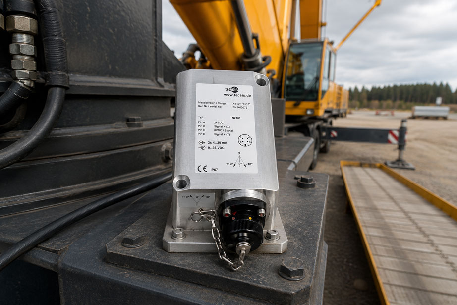
A dual-axis inclination sensor is mounted on the frame of an aerial work platform. The machine appears to be almost perfectly level, yet the control system indicates +1.2° roll and -0.8° pitch. After a zero-point correction, the indication is correct in the level position. However, as soon as the platform is tilted only in the longitudinal direction, the second measuring channel suddenly changes as well.
In another case, the sensor itself works correctly, but the control system reports a negative instead of a positive angle when the machine tilts to the right. The cause is neither a defective sensing element nor incorrect calibration, but a different definition of sensor axes and vehicle coordinates.
Such errors are particularly common when commissioning inclination sensors. A dual-axis sensor does not automatically provide the required variables “roll” and “pitch”. First, it must be clearly defined which mechanical sensor axis corresponds to which machine axis, which direction of rotation is positive and which plane defines the zero point.
Mounting errors, cross-axis sensitivity, temperature behavior, vibration and dynamic acceleration must also be taken into account. A zero-point adjustment can correct a small constant offset. However, it cannot correct a sensor that has been mounted at an angle or an incorrect axis assignment.
Suitable sensors can be found at ICS Schneider under inclination sensors. An overview of additional sensors for mechanical measured variables can be found under displacement, force and motion sensors.
Table of Contents
- What does an inclination sensor measure?
- Distinguishing between single-axis and dual-axis inclination sensors
- Distinguishing between sensor, vehicle and world coordinate systems
- Defining roll and pitch correctly
- Why a standard inclination sensor cannot determine yaw
- Checking axis direction and sign before parameterization
- Mounting surface and mechanical alignment
- Defining the zero point correctly
- Correcting offset without hiding mounting errors
- What does cross-axis sensitivity mean?
- How rotated mounting couples both axes
- Checking combined roll and pitch angles
- Temperature drift and thermal equilibrium
- Dynamic acceleration and vibration
- Filtering: stable measured value versus response time
- Limit values, hysteresis and delay
- Dual-axis measurement is not the same as redundancy
- Checking output signal and scaling
- Functional test on a defined reference plane
- Which test points are useful?
- Typical fault patterns during commissioning
- Step-by-step commissioning
- Practical example: aerial work platform shows lateral angle during longitudinal inclination
- Suitable WIKA inclination sensors
- Conclusion
- FAQ
What does an inclination sensor measure?
An inclination sensor, or inclinometer, determines the spatial inclination of an object relative to the direction of Earth’s gravity.
Typical applications include:
- mobile cranes,
- aerial work platforms,
- construction machinery,
- agricultural machinery,
- booms and platforms,
- leveling systems,
- marine and offshore applications,
- solar systems.
Depending on the sensor version, the output is provided as an analog or digital signal or directly as a calculated angle value.
For the machine, however, the measured angle alone is not the only important factor. An equally important question is:
Which mechanical axis does this angle belong to?
This assignment must be clearly defined for a dual-axis sensor before the actual parameterization is carried out.
Distinguishing between single-axis and dual-axis inclination sensors
Single-axis inclination sensor
A single-axis inclination sensor essentially monitors one defined direction of rotation.
Typical applications include:
- boom angle of a crane,
- inclination of a lifting arm,
- angle of an individual flap or platform.
If only this one movement is relevant, a single-axis measuring principle may be sufficient.
Dual-axis inclination sensor
A dual-axis sensor detects two independent directions of inclination.
On a mobile machine, these are often referred to as:
- roll and
- pitch
.
This makes it possible, for example, to monitor simultaneously whether a vehicle:
- is tilted sideways,
- and is positioned uphill or downhill in the longitudinal direction.
However, the sensor designations “X axis” and “Y axis” are not automatically identical to the machine’s roll and pitch directions.
This assignment is determined by the mounting orientation.
Distinguishing between sensor, vehicle and world coordinate systems
When commissioning a dual-axis inclination sensor, several coordinate systems interact.
1. Sensor coordinate system
The sensor has its own defined axes, for example:
- XS,
- YS,
- ZS.
These axes are defined by the mechanical design of the sensor or by the manufacturer’s specification.
2. Machine coordinate system
The machine may, for example, be defined as follows:
- XM = forward direction of travel,
- YM = lateral vehicle direction,
- ZM = vertically upward.
Other manufacturers may use different definitions.
3. Functional coordinates
The control software may not use X and Y, but instead:
- roll,
- pitch,
- lateral inclination,
- longitudinal inclination.
Before the electrical connection is made, the following should therefore already be documented:
Sensor axis → machine axis → functional designation → positive direction of rotation.
Without this assignment, a technically correctly functioning sensor can appear to provide completely incorrect values in the control system.
Defining roll and pitch correctly
The terms roll and pitch are frequently used in vehicle applications.
Roll
Roll generally refers to rotation about the vehicle’s longitudinal axis.
A typical example:
The left wheels are higher than the right wheels. The vehicle therefore has a lateral inclination.
Pitch
Pitch generally refers to rotation about the vehicle’s transverse axis.
A typical example:
The front axle of the vehicle is higher than the rear axle.
These terms are commonly used in many technical applications, but the actual definition used by the specific machine control system must still be checked.
The sign convention is also particularly important.
For example, the following could be defined:
- right side lower = +roll,
- right side higher = -roll,
- vehicle front higher = +pitch,
- vehicle front lower = -pitch.
Another control system may use exactly the opposite sign convention.
Why a standard inclination sensor cannot determine yaw
In addition to roll and pitch, there is a third familiar orientation variable: yaw.
Yaw describes rotation about the vertical axis.
Such a rotation changes the orientation relative to a compass direction, but does not necessarily change the direction of the gravity vector relative to the sensor.
A purely gravity-based inclination sensor therefore cannot determine an absolute yaw angle from static measurement of Earth’s gravity.
Depending on the application, additional measured variables or other sensor technologies are required for complete spatial orientation.
This distinction is important because a sensor with X, Y and Z references does not automatically constitute a complete three-axis orientation system.
Checking axis direction and sign before parameterization
The axis direction should be checked before carrying out a zero-point adjustment.
For this purpose, the machine or a defined test plane is deliberately tilted in only one direction.
Example:
- The sensor is approximately in the zero position.
- The machine is tilted exclusively to the right.
- Observe which sensor channel responds.
- Document the sign of the measured value.
- Return the machine to zero.
- Then tilt the machine only in the longitudinal direction.
- Check the second channel.
This procedure can already identify several typical errors:
- X and Y have been interchanged,
- one axis has the wrong sign,
- the sensor has been mounted rotated by 90°,
- the sensor is slightly rotated relative to the machine axes.
This check should be carried out before the zero-point adjustment.
An offset cannot correct an incorrect axis definition.
Mounting surface and mechanical alignment
The accuracy of an inclination sensor begins with its mounting surface.
Ideally, this surface is:
- flat,
- rigid,
- clean,
- free of burrs,
- mechanically stable,
- clearly aligned with the machine geometry.
Problematic examples include:
- thin sheet metal that deforms when the screws are tightened,
- mounting on a painted or uneven surface,
- sensor brackets with mechanical play,
- mounting surfaces that are themselves not parallel to the required reference plane.
A sensor can have very high measurement accuracy and still provide an incorrect machine angle if its mounting surface is already rotated by 1° relative to the required reference plane.
For high accuracy requirements, it should therefore not be assumed that any arbitrary chassis surface automatically represents the machine reference.
Defining the zero point correctly
The zero point is the mechanical position that the control system is intended to interpret as 0°.
Before carrying out a zero adjustment, it must therefore first be defined what “level” means for the specific machine.
Possible references include:
- a defined machined surface on the chassis,
- a reference surface on the machine frame,
- a calibrated leveling plane,
- a chassis position defined by the machine manufacturer.
For a mobile machine, the mechanical operating conditions should also be defined.
For example:
- boom retracted or extended?
- outriggers retracted or loaded?
- tire pressure defined?
- machine unloaded or carrying a defined load?
- turntable in which position?
These factors can slightly deform the machine frame or change its position.
A reproducible zero point therefore requires a reproducible mechanical reference condition.
Correcting offset without hiding mounting errors
A small zero-point error may remain after mounting.
Example:
The reference plane is exactly at 0.00°, but the sensor indicates:
- X = +0.18°,
- Y = -0.11°.
If the mounting, axis direction and reference plane have been checked, such constant deviations can, depending on the system, be compensated by a zero-point or offset correction.
Problems arise when the zero adjustment is used to hide a mechanical installation error.
Example:
The sensor is mounted rotated by 3° relative to the machine’s longitudinal axis.
On a level surface, both channels can still be adjusted to a perfect zero point.
However, as soon as the machine is tilted, coupling occurs between the two measuring axes.
A zero adjustment corrects a constant offset, but not a rotational misalignment between the sensor and machine coordinate systems.
What does cross-axis sensitivity mean?
Cross-axis sensitivity generally refers to the influence of a measured variable from another direction on the measuring channel actually being evaluated.
For dual-axis inclination sensors, two different causes should be distinguished.
Internal cross-axis sensitivity of the sensor
Due to its design, the sensing element itself may have a certain sensitivity to movements or inclinations outside its ideal measuring axis.
This effect is one of the technical characteristics of the sensor.
Apparent cross-axis sensitivity caused by mounting errors
Much more common in practice is geometric coupling caused by the sensor being mounted rotated relative to the machine axes.
The sensor’s X axis then no longer measures only the required machine X direction, but a component of both machine axes.
The resulting observation may be:
“When I change only pitch, roll changes as well.”
This does not necessarily mean that the sensor has poor cross-axis sensitivity.
It may simply mean that the sensor and machine coordinate systems are not aligned correctly.
How rotated mounting couples both axes
For small angles, the effect of a rotation between the sensor and machine coordinate systems can be illustrated in simplified form.
If the sensor is rotated within its mounting plane by the angle α relative to the machine axes, the following approximate relationships may result:
XSensor ≈ XMachine · cos(α) + YMachine · sin(α)
YSensor ≈ -XMachine · sin(α) + YMachine · cos(α)
The equations illustrate the key effect:
Even a small rotational misalignment introduces a component of the other machine axis into the sensor signal.
With small mounting errors, this effect can easily be overlooked.
On a perfectly level surface, both channels can show exactly 0° after zeroing.
The coupling only becomes visible when one machine axis is deliberately tilted while the other remains unchanged.
A separate X/Y functional test should therefore always form part of commissioning.
Checking combined roll and pitch angles
A basic test consisting of:
- roll = 0°, pitch = 0°,
- roll ≠ 0°, pitch = 0°,
- roll = 0°, pitch ≠ 0°
is a good starting point.
For a more complete functional test, however, at least one combined inclination should also be checked.
Example:
- roll = +5°,
- pitch = +5°.
or:
- roll = -5°,
- pitch = +5°.
This can reveal errors that may not become apparent during pure single-axis testing.
At larger inclination angles, it must also be taken into account that spatial rotations cannot simply be treated mathematically as two completely independent linear variables.
Parameterization and evaluation should therefore always follow the coordinate model specified by the sensor or machine manufacturer.
Temperature drift and thermal equilibrium
Inclination sensors in mobile machines are often exposed to wide temperature ranges.
For example:
- the machine remains outdoors overnight at -15 °C,
- the hydraulic system and engine warm up after start-up,
- solar radiation heats one side of the machine frame,
- the sensor is located near a heat source.
Both the sensor electronics and the mechanical mounting can change slightly with temperature.
It is therefore useful not to assess the zero point only immediately after mounting at a single temperature.
For demanding applications, the following should be checked:
- zero point at room temperature,
- behavior after a cold start,
- behavior after thermal warm-up,
- return of the zero point after a temperature cycle.
If the sensor and machine structure are still changing thermally, a temporary zero-point deviation should not immediately be compensated by another adjustment.
Dynamic acceleration and vibration
Many inclination sensors determine their orientation relative to Earth’s gravity.
For a stationary or slowly moving machine, this reference works well.
However, during strong acceleration, shocks or vibration, additional mechanical influences may occur.
Typical situations include:
- hard braking,
- rapid acceleration,
- driving over uneven ground,
- oscillation of a boom,
- hydraulic load changes,
- shocks when a platform is set down.
With gravity-based or acceleration-based measuring principles, such dynamic influences can be superimposed on the signal used for inclination measurement.
It must therefore already be clarified during sensor selection:
Should the sensor measure a static or quasi-static position, or must it provide a stable inclination angle during strong machine movement?
For highly dynamic applications, special dynamic inclination systems with additional filtering or sensor fusion may be required.
Filtering: stable measured value versus response time
A filter can smooth fluctuating sensor values.
Stronger damping can reduce, for example:
- high-frequency noise,
- vibration effects,
- short-term peaks.
At the same time, however, the response time increases.
A heavily filtered sensor can therefore provide a very stable measured value while responding more slowly to an actual critical change in inclination.
The filter setting must therefore always match the function.
| Application | Filtering tendency |
|---|---|
| Slow leveling of a platform | Stronger damping may be useful |
| Static stability monitoring | Stable, reproducible value is important |
| Fast movement monitoring | Pay particular attention to response time |
| Strong vibration | Damping required, but delay must be evaluated |
For safety-related functions, the response time of the entire signal chain must be considered, not just the sensor’s internal filter time.
Limit values, hysteresis and delay
Inclination sensors are often used not only to indicate an angle, but also to monitor limit values.
Example:
- warning from 3°,
- movement limitation from 4°,
- shutdown above a defined limit value.
A limit value should not be considered in isolation.
Additional relevant factors include:
- measurement uncertainty,
- zero-point deviation,
- temperature behavior,
- vibration,
- filter time,
- hysteresis,
- switching delay.
Hysteresis
Without hysteresis, a measured value directly at the limit can continuously switch between “permitted” and “not permitted”.
Example:
Switch-on limit = 4.0°
Reset value = 3.5°
The specific design depends on the machine function and the safety concept.
Delay
A short time delay can prevent an individual vibration impulse from immediately triggering a reaction.
However, an excessively long delay can slow down the actual response of the machine to an unacceptable degree.
Limit value, hysteresis, filtering and delay must therefore be considered as interrelated parameters.
Dual-axis measurement is not the same as redundancy
The terms dual-axis and redundant are sometimes confused.
However, they describe completely different characteristics.
| Characteristic | Meaning |
|---|---|
| Dual-axis | The sensor measures two different directions of inclination |
| Redundant | A measured variable or measuring function is available via additional independent signal paths or measuring channels |
A dual-axis sensor can therefore measure X and Y without being redundant.
A redundant sensor, on the other hand, can provide the same angle via two signal paths, for example.
For cranes, aerial work platforms and other machines, redundant measurements can form part of a safety concept.
However, the presence of a redundant sensor alone does not automatically make a machine function functionally safe.
The complete architecture, diagnostics, control system, actuators, fault reactions and the applicable standards or safety requirements must also be considered.
Checking output signal and scaling
After mechanical commissioning, the electrical scaling must be checked.
Depending on the sensor version, inclination sensors may provide analog or digital output signals.
Typical interfaces in this device class may include:
- 4–20 mA,
- 0–10 V,
- PWM,
- CANopen,
- serial or digital interfaces.
With an analog signal, the control system must correctly convert the electrical range into the corresponding angular range.
Example:
If a specific sensor version uses a symmetrical angular range, the control system must clearly define:
- which signal corresponds to the negative end point,
- which signal corresponds to the zero point,
- which signal corresponds to the positive end point.
For digital sensors, additional parameters may also need to be checked, such as:
- device address,
- baud rate,
- data format,
- unit,
- sign convention,
- axis designation.
Incorrect scaling can result in a mechanically correctly mounted sensor measuring 5°, while the PLC calculates 10° from the signal.
Functional test on a defined reference plane
After mounting and parameterization, the sensor should not be tested only in its zero position.
A suitable reference may be, for example:
- a defined inclination test fixture,
- a precisely adjustable plane,
- a suitable calibrated angular reference.
The basic test procedure is:
- Set the reference plane to 0°.
- Document sensor values X and Y.
- Correct the zero point only if necessary and after checking the geometry.
- Apply a positive X inclination.
- Apply a negative X inclination.
- Apply a positive Y inclination.
- Apply a negative Y inclination.
- Check at least one combined X/Y point.
- Check the return to 0°.
This simultaneously checks:
- zero point,
- sign convention,
- axis assignment,
- approximate scaling,
- cross-axis influence,
- repeatability.
Which test points are useful?
The specific test points depend on the measuring range and actual application.
For a sensor that mainly operates within ±10°, for example, the following points could be useful:
| Test | Example |
|---|---|
| Zero point | X = 0°, Y = 0° |
| X positive | X = +5°, Y = 0° |
| X negative | X = -5°, Y = 0° |
| Y positive | X = 0°, Y = +5° |
| Y negative | X = 0°, Y = -5° |
| Combination 1 | X = +5°, Y = +5° |
| Combination 2 | X = -5°, Y = +5° |
| Return | X = 0°, Y = 0° |
For a simple functional test, these values do not necessarily constitute a complete calibration.
For high accuracy or safety requirements, a defined test plan with a suitable traceable reference is required.
Typical fault patterns during commissioning of inclination sensors
| Observation | Possible cause | Recommended check |
|---|---|---|
| Both axes show a constant non-zero value on a level surface | Zero-point offset or tilted mounting surface | Check reference plane and mounting surface, then apply offset if required |
| The longitudinal inclination channel responds to lateral inclination | X/Y axes interchanged or sensor rotated by 90° | Perform a single-axis functional test |
| Angle changes with the wrong sign | Positive direction of rotation defined incorrectly | Compare the sign convention of the sensor and control system |
| Y changes during pure X inclination | Sensor rotated relative to machine axis or cross-axis sensitivity | Check mechanical alignment and perform a cross-axis test |
| Zero point is correct after adjustment, but larger angles are incorrect | Mechanical rotational error or incorrect scaling | Apply several positive and negative test points |
| Angle fluctuates strongly while the engine is running | Vibration or dynamic acceleration | Compare measured value with the machine stationary and check filtering |
| Sensor responds too slowly | Excessive filtering or damping | Check filter parameters and required response time |
| Sensor value is stable, but limit response is delayed | Filter delay and additional control-system delay are cumulative | Check the timing of the complete signal chain |
| Zero point changes between cold and warm machine conditions | Temperature dependence of the sensor or mounting | Check temperature cycle and mechanical reference |
| X and Y are interchanged after sensor replacement | Different mounting orientation or parameterization | Verify axis function after every sensor replacement |
| Redundant channels differ | Different scaling, wiring or an actual sensor fault | Check both channels separately against the same reference |
Step-by-step commissioning of a dual-axis inclination sensor
A structured procedure prevents mechanical errors from later being hidden by software parameters.
- Define the measurement task: Which angles actually need to be measured?
- Define the coordinate system: Document machine X, machine Y and machine Z.
- Define roll and pitch: Determine which machine movement corresponds to which measuring channel.
- Define sign convention: Document positive and negative directions of rotation.
- Check measuring range: The sensor range must cover the actual operating range including reserves.
- Check mounting surface: Verify flatness, rigidity and alignment.
- Mount the sensor without mechanical stress: Install according to the manufacturer’s specifications.
- Check electrical connection: Verify supply, signal, connector and cable.
- Read raw values: Do not yet perform a zero-point correction.
- Functionally test the X axis: Deliberately tilt the machine in only one direction.
- Functionally test the Y axis: Check the second direction of movement separately.
- Confirm the sign: The measured value must correspond to the machine convention.
- Check cross-axis influence: During pure X inclination, observe how much Y changes and vice versa.
- Correct mechanical alignment: If the axes do not coincide correctly.
- Establish the reference plane: Place the machine in the defined zero position.
- Allow temperature to stabilize: Wait for thermal equilibrium if necessary.
- Set the zero point: Only now correct the permissible offset.
- Check several angle points: Positive and negative on both axes.
- Check a combined angle: Deflect both axes simultaneously.
- Set the filter: Select a compromise between stability and response time.
- Check limit values: Consider hysteresis and delay.
- Perform a dynamic test: Observe the measurement behavior during actual machine movement.
- Check return to zero: Return to the reference position after the movement cycle.
- Document parameters: Record axes, sign convention, offset, filter and limit values.
- Document the functional test: Record the actual test angles and results.
Practical example: aerial work platform shows lateral angle during longitudinal inclination
A dual-axis inclination sensor is replaced on a mobile aerial work platform.
After mounting, the vehicle is positioned on a defined level surface.
The sensor indicates:
- roll = +0.4°,
- pitch = -0.3°.
The values are adjusted to 0° using the zero-point correction.
At first glance, commissioning appears to be complete.
Step 1: Check longitudinal inclination
The front of the machine is raised by approximately 6° on a defined ramp.
The control system indicates:
- pitch = +5.8°,
- roll = +0.7°.
Because the machine was tilted almost exclusively in the longitudinal direction, the change in the roll value is noticeable.
Step 2: Check sensor mounting
The mounting surface is inspected.
It becomes apparent that the sensor bracket is not mounted exactly parallel to the vehicle’s longitudinal axis.
The sensor is slightly rotated within the horizontal mounting plane.
Step 3: Correct mechanical alignment
The sensor bracket is aligned correctly with the vehicle axis.
The mounting is then tightened securely.
Step 4: Determine the zero point again
The machine is returned to the defined reference surface.
Only after correcting the mechanical mounting is the remaining small offset determined again and corrected if necessary.
Step 5: Recheck the individual axes
At approximately +6° longitudinal inclination, almost only the pitch channel now changes.
A lateral inclination is then applied. The roll channel now responds predominantly, as expected.
Step 6: Check combined inclination
Finally, a position is approached in which the machine is tilted both longitudinally and laterally.
Both measuring channels respond plausibly and with the defined sign convention.
Result: The sensor was not defective. The original zero-point adjustment had merely hidden the offset on the level surface. The actual cause was a rotational misalignment between the sensor and vehicle coordinate systems.
The example illustrates the most important principle:
First check axis direction and mechanical alignment – then set the zero point.
Suitable WIKA inclination sensors for mobile machines and crane applications
WIKA Type N2101 – dual-axis inclination sensor for X/Y/Z directions
For the dual-axis inclination measurement described in this article, the WIKA Type N2101 is particularly suitable.
The sensor allows two directions of rotation to be selected from the X, Y and Z directions and is intended for applications such as:
- crane systems,
- mobile cranes,
- ship cranes,
- aerial work platforms,
- solar systems
.
Specified characteristics include:
- two freely selectable axes,
- freely selectable measuring range between -45° and +45°,
- relative linearity deviation < 0.1% of full scale over the entire measuring range,
- measured-value resolution of 0.01°,
- good damping behavior,
- IP67 degree of protection,
- seawater-resistant design.
Especially in dual-axis applications, it must already be clearly defined during ordering and installation which sensor directions are to be assigned to the machine axes.
Further information can be found under WIKA Type N2101 at ICS Schneider.
WIKA Type N1101 – inclination sensor for single-axis 0…360° measurements
If dual-axis platform inclination is not required and instead a single angle over a large rotational range needs to be measured, the WIKA Type N1101 may be a suitable alternative.
The sensor is designed for measuring ranges up to 0…360° and is used, for example, in:
- crane systems,
- mobile machines,
- aerial work platforms,
- solar systems
.
For typical tasks such as measuring a single boom angle, a single-axis concept is often clearer than an unnecessarily complex dual-axis measurement.
Further information can be found under WIKA Type N1101 at ICS Schneider.
WIKA Type N1301 – redundant inclination sensor
For applications requiring a redundant measuring concept, the WIKA Type N1301 is available.
The sensor is designed for a measuring range of 0…360° and is intended as a redundant version.
Specified characteristics include:
- measuring range 0…360°,
- relative linearity deviation < 0.1% of full scale,
- measured-value resolution of 0.01°,
- IP67 degree of protection,
- seawater-resistant design.
However, the distinction described above is important:
The N1301 is a redundant solution, whereas the N2101 is designed for dual-axis inclination measurement. Redundancy and dual-axis measurement serve different purposes.
Further information can be found under WIKA Type N1301 at ICS Schneider.
WIKA Type N131C – redundant Ex d inclination sensor
For applications in hazardous areas, WIKA also offers the Type N131C, a redundant inclination sensor with flameproof Ex d enclosure.
Typical applications include:
- offshore installations,
- offshore cranes,
- drilling equipment,
- mobile cranes,
- ship cranes,
- oil and gas industry.
The specific version must also be selected according to the application area, hazardous-area requirements and overall system concept.
Further information can be found under WIKA Type N131C at ICS Schneider.
Which sensor type is suitable for the application?
| Requirement | Suitable sensor version |
|---|---|
| Measure roll and pitch simultaneously | Dual-axis inclination sensor, for example WIKA N2101 |
| Measure a single boom angle | Single-axis inclination sensor |
| Large angular range up to 360° | Corresponding 360° version, for example N1101 |
| Redundant angle measurement | Redundant sensor version, for example N1301 |
| Redundant measurement in hazardous areas | Suitable Ex version, for example N131C |
| Strong machine movement and dynamic acceleration | Check dynamic behavior and, if necessary, a dedicated sensor principle separately |
An overview of the currently available devices can be found under inclination sensors at ICS Schneider.
Conclusion
Successful commissioning of a dual-axis inclination sensor does not begin with zero-point adjustment, but with defining the coordinate system.
First, the following must be clearly defined:
- Which sensor axis corresponds to which machine axis?
- Which axis is referred to as roll or pitch?
- Which direction of rotation is positive?
- Which mechanical plane defines 0°?
Only then should the sensor be mounted permanently and the remaining zero-point offset be determined.
It is particularly important to distinguish between a genuine sensor fault and apparent cross-axis sensitivity caused by rotated mounting. A sensor can be perfectly adjusted to 0° on a level surface and still show incorrect components on both channels when the machine is subsequently tilted.
A useful functional test should therefore always include:
- zero position,
- positive and negative X inclination,
- positive and negative Y inclination,
- at least one combined X/Y inclination,
- return to the zero point.
For mobile machines, temperature, vibration and dynamic acceleration must also be taken into account. Stronger filtering can stabilize the measured value, but increases the response time.
For limit functions, the sensor, filtering, control system, hysteresis and switching delay must therefore be evaluated as a complete signal chain.
It is equally important to distinguish between dual-axis measurement and redundancy: Two measuring axes detect two spatial directions, whereas redundancy provides additional availability or monitoring of a measuring function.
The most important sequence for commissioning is therefore:
Define coordinate system → mechanically align sensor → check axes and signs → check cross-axis influence → establish reference plane → set zero point → check several angle points → test filter and limit values → verify under actual machine movement.
FAQ: Setting up a dual-axis inclination sensor correctly
What is a dual-axis inclination sensor?
A dual-axis inclination sensor measures the inclination of an object in two directions. On mobile machines, these are often used to determine roll and pitch or lateral and longitudinal inclination.
What is the difference between a single-axis and a dual-axis inclination sensor?
A single-axis sensor measures one defined direction of inclination. A dual-axis sensor can measure two different directions of inclination simultaneously.
What does roll mean for an inclination sensor?
For vehicles, roll generally refers to rotation about the longitudinal axis and therefore essentially corresponds to lateral inclination.
What does pitch mean?
Pitch generally refers to rotation about the vehicle’s transverse axis and therefore describes longitudinal inclination forward or backward.
Are the X axis and roll always the same?
No. The sensor axes are defined by the manufacturer. Only the mounting orientation determines which sensor axis corresponds to the roll or pitch direction of the machine.
Why must the axis direction be checked before setting the zero point?
A zero-point adjustment only corrects an offset. It does not identify whether X and Y have been interchanged or whether the sensor has been mounted at an angle.
How do you check the axis direction of an inclination sensor?
The machine or test fixture is deliberately tilted in only one direction. It is then checked which measuring channel responds and which sign the measured value has. The second axis is then checked separately.
How is the zero point of an inclination sensor set?
First, a defined mechanical reference position must be established. After checking mounting, axes and signs, the remaining constant offset can be corrected according to the specifications of the measuring system.
Can an inclined mounting position simply be corrected using the zero point?
A small constant angular difference in the measuring direction can be taken into account as an offset. However, a rotational misalignment between sensor and machine axes should be corrected mechanically because it can cause coupling between the two axes.
Why does the second axis show a value even though the machine has only been tilted in one direction?
A common cause is that the sensor is mounted rotated relative to the machine coordinate system. Other possible causes include actual cross-axis sensitivity, an inaccurate test fixture or a real combined inclination.
What does cross-axis sensitivity mean for an inclination sensor?
Cross-axis sensitivity describes the influence of movement or inclination outside the measuring direction being evaluated on the measuring channel. In practice, a distinction should be made between internal sensor cross-axis sensitivity and geometric axis coupling caused by incorrect mounting.
Can a zero-point adjustment eliminate cross-axis sensitivity?
No. A zero-point adjustment changes a constant offset. Geometric coupling between X and Y remains as inclination increases.
Why should both positive and negative angles be checked?
This makes it possible to detect sign errors, different deviations on either side of the zero point and possible scaling or mechanical problems.
Why should a combined X/Y inclination also be checked?
This verifies whether both measuring channels also behave plausibly when lateral and longitudinal inclination occur simultaneously. Certain axis or transformation errors only become visible at combined angles.
Can an inclination sensor measure yaw?
A purely gravity-based inclination sensor can determine roll and pitch from static Earth’s gravity, but not an absolute yaw angle about the vertical axis. Additional measuring principles are required for this.
Does temperature influence the zero point?
Depending on the sensor and mechanical design, the measured value and mounting condition may change slightly with temperature. For demanding applications, behavior over the relevant temperature range should therefore be checked.
Why should the sensor not be adjusted immediately after a major temperature change?
The sensor, housing and machine structure may still be reaching thermal equilibrium. A zero-point correction made during this phase can result in a new offset once the temperature has stabilized.
Why does an inclination sensor fluctuate while the machine is moving?
Vibration, shocks and dynamic acceleration can influence the inclination signal. The severity of the effect depends on the measuring principle, mounting, filtering and machine movement.
Does stronger filtering help against vibration?
Yes. Stronger filtering can damp rapid fluctuations. However, it also increases the response time. The filtering must therefore be matched to the actual machine function.
What does filter time mean for a limit value?
The more strongly a signal is smoothed, the later an actual angle change may become fully visible at the output or in the control system. For limit functions, the total response time must therefore be considered.
Why does an inclination limit require hysteresis?
Hysteresis prevents a measured value directly at the limit from continuously switching back and forth between two states. The reset point is therefore separated slightly from the activation point.
Is a dual-axis sensor automatically redundant?
No. A dual-axis sensor measures two different spatial directions. A redundant sensor, on the other hand, provides a measuring function via additional measuring or signal paths.
When is a redundant inclination sensor useful?
Redundant measurements can form part of monitoring and safety concepts, for example on cranes or aerial work platforms. The specific requirement, however, results from the risk assessment and safety concept of the complete machine.
Does a redundant sensor automatically make an application functionally safe?
No. Functional safety must be considered at the level of the complete safety function. This includes, among other things, sensors, diagnostics, control system, actuators, fault response and the applicable normative requirements.
How should an inclination sensor be mounted mechanically?
It should be mounted in accordance with the manufacturer’s specifications on a solid, rigid and preferably flat surface. Loose brackets, mechanical stress and unnecessary vibration coupling should be avoided.
Can a sensor be mounted on thin sheet metal?
This can be problematic if the sheet metal deforms when the screws are tightened, under load or as a result of temperature. The mounting surface should reproduce the orientation of the machine component being monitored in a stable and repeatable way.
Which points should be checked after replacing a sensor?
At minimum, the axis assignment, sign convention, zero point, scaling, positive and negative angles of both axes and the limit function should be checked again.
Which reference is suitable for checking an inclination sensor?
Depending on the accuracy requirement, a defined inclination test fixture or a suitable calibrated angular reference can be used. The reference must be more accurate and sufficiently stable for the intended test.
Which WIKA sensor is suitable for dual-axis inclination measurement?
For corresponding applications, the WIKA Type N2101 is one suitable option. It allows two freely selectable axes and a freely selectable measuring range within a maximum range of -45° to +45°.
What resolution does the WIKA N2101 provide?
The WIKA Type N2101 is specified with a measured-value resolution of 0.01°.
What degree of protection does the WIKA N2101 provide?
The WIKA Type N2101 is specified with IP67 protection and is intended for rugged applications such as crane systems, mobile cranes and aerial work platforms.
Is a redundant WIKA inclination sensor also available?
Yes. The WIKA Type N1301 is available as a redundant inclination sensor with a measuring range of 0…360°. For hazardous-area applications, the N131C is additionally available as a redundant version with flameproof Ex d enclosure.