


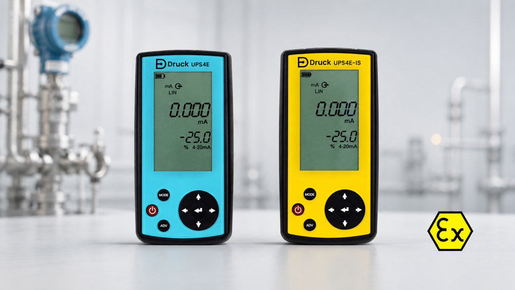
The 4–20 mA signal is one of the most important standard signals in industrial measurement technology. Pressure transmitters, temperature transmitters, level sensors, flow meters, positioners and many other field devices transmit their measured values via a current loop to a PLC, control system, controller or display.
If measured values are not plausible, the PLC displays incorrect values or a transmitter does not work correctly after replacement, the current loop must be checked systematically. This is not only about measuring the current. In many cases, a 4–20 mA signal also has to be simulated, actively sourced or tested with 24 V loop supply.
A loop calibrator such as the UPS4E Loop Calibrator is a very practical tool for this. It can measure and source mA signals, provide 24 V loop supply, display percentage values, approach test points, generate ramps, perform valve tests and support HART applications via an integrated 250 Ω resistor.
You can find suitable devices in the categories
process calibrators
and
simulators.
For testing 4–20 mA current loops, the
UPS4E loop calibrator
is particularly relevant. Depending on the application,
DPI620 GENII,
DPI802,
DPI880,
HT8051
or
HT8100
may also be suitable.
Table of contents
- What is a 4–20 mA signal?
- Why does a 4–20 mA signal need to be checked or calibrated?
- Structure of a 4–20 mA current loop
- Measuring, sourcing and simulating: the most important operating modes
- Understanding source and sink: active and passive current loops
- Using 24 V loop supply correctly
- 4–20 mA in percent: checking 0, 25, 50, 75 and 100 %
- Testing a PLC input with 4–20 mA
- Checking transmitters and signal converters
- Using step, span and ramp functions effectively
- Valve testing and checking positioners
- HART support with 250 Ω resistor
- Typical wiring errors and measurement errors
- UPS4E: compact loop calibrator for 4–20 mA
- Product comparison: which calibrator is suitable?
- Practical examples from maintenance and process instrumentation
- Checklist: checking a 4–20 mA current loop
- Conclusion
- FAQ: frequently asked questions about 4–20 mA calibration
What is a 4–20 mA signal?
A 4–20 mA signal is an analog current signal used to transmit measured values. The lower range value is typically transmitted with 4 mA, and the upper range value with 20 mA. The range between 4 and 20 mA corresponds to the usable measuring range of the device.
The advantage of a current signal is that it is much more robust against voltage drops on cables than a simple voltage signal. For this reason, 4–20 mA is widely used in the process industry, mechanical engineering, power plants, water and wastewater technology, chemical plants, petrochemical applications and building services.
Another advantage: 4 mA does not correspond to zero current. This makes it easier to detect a wire break or device failure. If 0 mA is suddenly present instead of 4 mA, this indicates an interruption, missing supply voltage or a fault in the current loop.
Why does a 4–20 mA signal need to be checked or calibrated?
In practice, the 4–20 mA signal is often the interface between the field device and automation. If an error occurs there, the PLC or control system displays an incorrect process value. This can lead to incorrect control, false alarms, plant shutdowns or quality problems.
Checking the current loop is particularly useful after replacing a transmitter, after wiring work, in the event of implausible measured values, during commissioning or during recurring maintenance. The focus should not only be on the field device, but on the entire measuring chain: sensor, transmitter, loop supply, cable, input card, display and scaling.
| Problem | Possible cause | Suitable check |
|---|---|---|
| PLC displays incorrect value | Scaling, input card or current signal faulty. | Simulate mA signal directly at the PLC input. |
| Transmitter provides no signal | No 24 V supply, wire break or incorrect wiring. | Check loop supply and current consumption. |
| Measured value jumps | Contact problem, interference or unstable supply. | Observe current signal over time. |
| Measuring range does not match | Incorrect LRV/URV or incorrect PLC scaling. | Check 4, 8, 12, 16 and 20 mA. |
| Valve moves incorrectly | Positioner, signal direction or calibration faulty. | Output mA signal in steps and as a ramp. |
Structure of a 4–20 mA current loop
A 4–20 mA current loop typically consists of a power supply, a transmitter or signal converter, the signal cable and an input in the PLC, controller, display or control system. Depending on the device, the loop can be active or passive.
With a 2-wire transmitter, supply and signal are carried over the same two wires. The transmitter modulates the current within the loop according to the measured value. With 3- or 4-wire devices, supply and signal can be routed separately.
For troubleshooting, it is essential to know where the current is being measured and which device supplies the loop. Many errors occur because two active sources work against each other or because a passive loop is tested without supply voltage.
Measuring, sourcing and simulating: the most important operating modes
A loop calibrator must cover different tasks. When measuring, the existing loop current is recorded. When sourcing, the calibrator itself generates a defined mA signal. When simulating, the calibrator behaves like a passive transmitter and requires an external loop supply.
This distinction is important because the measuring task determines how the calibrator is connected. Anyone who wants to test a PLC input usually sources an mA signal. Anyone who wants to check an existing transmitter measures the current in the loop. Anyone who wants to simulate a passive transmitter uses the existing 24 V loop supply.
| Operating mode | What does the calibrator do? | Typical application |
|---|---|---|
| Measure mA | Records the existing current in the loop. | Checking transmitter output or current loop. |
| Source mA | Actively generates a defined current signal. | Testing PLC input, display or controller. |
| Simulate mA / sink | Simulates a passive transmitter in an externally supplied loop. | Checking measuring loop with existing 24 V supply. |
| 24 V loop supply | Supplies a passive transmitter. | Testing a field device without external supply. |
Understanding source and sink: active and passive current loops
The terms source and sink often lead to confusion in practice. In source mode, the calibrator provides the current itself. It is therefore the active source. In sink or simulation mode, an external source provides the voltage, and the calibrator regulates the current like a passive transmitter.
If the wrong operating mode is selected, typical problems occur: no current flows, the display remains at 0 mA, a fuse trips or two supplies work against each other. Before connecting the calibrator, it should therefore be clarified whether the loop is active or passive.
A structured approach helps in the field: first check whether 24 V is present. Then clarify whether the device under test supplies current or requires current. Then select the appropriate operating mode on the calibrator.
Using 24 V loop supply correctly
Many 4–20 mA transmitters require a 24 V loop supply. If this supply is not available in the plant or if the transmitter is being tested on the workbench, a calibrator with integrated 24 V supply is particularly helpful.
The UPS4E can provide a 24 V loop supply. This allows passive transmitters to be powered while the mA signal is checked at the same time. This is particularly practical during commissioning, troubleshooting or preliminary testing of a transmitter.
It is important to observe polarity and the permitted load. An incorrectly connected loop supply is a common cause of measurement errors. The input load of the PLC, additional HART resistors and cable lengths can also influence the loop.
4–20 mA in percent: checking 0, 25, 50, 75 and 100 %
When calibrating 4–20 mA signals, percentage points are often used. 4 mA corresponds to the lower range value, i.e. 0 %. 20 mA corresponds to the upper range value, i.e. 100 %. The intermediate points can be derived easily.
| Percentage value | Current signal | Typical purpose |
|---|---|---|
| 0 % | 4 mA | Check lower range value. |
| 25 % | 8 mA | Check linearity in the lower range. |
| 50 % | 12 mA | Check midpoint and scaling. |
| 75 % | 16 mA | Check linearity in the upper range. |
| 100 % | 20 mA | Check upper range value. |
These points are well suited for checking PLC inputs, displays, recorders and controllers. If an input is correctly scaled, each mA value must correspond to the matching process value. Example: a pressure transmitter is scaled to 0 to 10 bar. Then 4 mA must equal 0 bar, 12 mA must equal 5 bar and 20 mA must equal 10 bar.
Testing a PLC input with 4–20 mA
A frequent application is testing a PLC input. For this, the transmitter is disconnected and the calibrator applies a defined mA signal to the input. The PLC or control system is then checked to see whether the displayed process value is correct.
This test is particularly helpful when it is unclear whether the fault comes from the field device or the automation system. If the PLC reacts correctly at 4, 12 and 20 mA, the input card and scaling are probably correct. If the values do not match, the PLC scaling, wiring or input must be checked.
During the test, it should be documented which current value was applied and which process value was displayed. This makes scaling errors easy to identify.
Checking transmitters and signal converters
With a transmitter, the check verifies whether the output signal matches the input signal or process value. With a pressure transmitter, for example, a defined pressure is applied and the 4–20 mA signal is measured. With a temperature transmitter, a sensor signal can be simulated or the mA output can be checked.
It is important to distinguish between a pure signal check and a complete calibration of the measuring chain. A pure mA check shows whether the output signal is transmitted correctly. A complete calibration additionally considers the sensor, process value, reference and conversion inside the transmitter.
For service work, an mA check is still very valuable. It quickly shows whether signal, wiring, supply voltage and scaling are plausible.
Using step, span and ramp functions effectively
A modern loop calibrator can not only output individual mA values, but also generate automatic steps or ramps. This saves time and makes tests more reproducible.
Step functions are suitable for typical test points such as 4, 8, 12, 16 and 20 mA. A ramp function changes the signal continuously over a defined range. This makes it possible to check whether displays, controllers, PLC inputs or actuators respond cleanly across the entire range.
This is particularly helpful during commissioning and troubleshooting. The technician can change the signal in a targeted way and observe whether the plant responds as expected.
Valve testing and checking positioners
4–20 mA is not only used for measured values, but also for controlling positioners and valves. In such cases, a loop calibrator can output a defined control signal and make the valve response visible.
A valve test helps to check whether a valve is closed at 4 mA, open at 20 mA or positioned according to the desired characteristic. Intermediate values such as 25, 50 and 75 % are also important for detecting friction, hysteresis or mechanical problems.
For safety-relevant or process-critical valves, a test may only be performed after approval and with suitable preparation. A simulated control signal can trigger real plant movement.
HART support with 250 Ω resistor
Many 4–20 mA transmitters also use HART communication. This often requires a minimum load in the current loop. A 250 Ω resistor is the typical value in many applications to support HART communication.
The UPS4E has an integrated 250 Ω resistor for HART support. This is particularly practical when a HART communicator or corresponding device is to be connected into the loop and the existing load is not sufficient.
Important: the resistor does not replace proper HART parameterization. It only creates a suitable loop condition so that communication can function reliably.
Typical wiring errors and measurement errors
Many errors in 4–20 mA current loops are simple, but very common in practice. These include incorrect polarity, missing 24 V supply, incorrect calibrator operating mode, wire break, incorrect PLC scaling or excessive load.
Confusion between active and passive inputs also occurs regularly. If a transmitter, PLC card and calibrator all act as active sources at the same time, the measurement cannot function correctly. Conversely, no current flows in a passive loop without supply voltage.
| Error | Typical symptom | Test approach |
|---|---|---|
| Incorrect polarity | 0 mA or no display. | Check connection and terminal assignment. |
| No loop supply | Passive transmitter provides no signal. | Measure 24 V or use loop supply. |
| Incorrect operating mode | Signal cannot be adjusted. | Select source/sink/measure correctly. |
| Incorrect scaling | PLC value does not match mA signal. | Apply 4, 12 and 20 mA and compare display. |
| Excessive load | Signal does not stably reach 20 mA. | Check load, cable length and input. |
UPS4E: compact loop calibrator for 4–20 mA
The
UPS4E loop calibrator
is particularly suitable for users who want to check 4–20 mA current loops quickly and reliably in the field. It can measure and source mA signals, provide 24 V loop supply and support typical test functions such as step, span, ramp and valve test.
The measurement and output range of 0 to 24 mA covers typical 4–20 mA applications including overrange and underrange. This means that not only standard points can be checked, but also fault ranges or diagnostic states can be evaluated more effectively.
The display of mA and percentage values is particularly practical. The technician immediately sees whether a signal at 4 mA corresponds to zero point, at 12 mA to midpoint or at 20 mA to the upper range value. This makes work on transmitters, PLC inputs and actuators much easier.
| UPS4E function | Benefit | Typical application |
|---|---|---|
| Measure and source 0–24 mA | Covers 4–20 mA and fault ranges. | Checking current loops, PLC inputs and transmitters. |
| 24 V loop supply | Passive transmitters can be powered directly. | Workbench test, commissioning and troubleshooting. |
| Step / span / ramp | Automatic test points and signal profiles. | Repeatable tests and functional checks. |
| Valve test | Actuators can be controlled in a targeted way. | Checking positioners and valves. |
| 250 Ω HART resistor | Supports HART communication. | Checking HART transmitters and loop conditions. |
Product comparison: which calibrator is suitable?
The suitable solution depends on whether only a simple current loop needs to be checked, whether a complete process calibrator is required or whether pressure, temperature, frequency or documentation are additionally needed. For pure 4–20 mA tasks, a compact loop calibrator such as the UPS4E is usually particularly efficient.
| Product / category | Suitable for | Typical application |
|---|---|---|
| UPS4E loop calibrator | Measuring, sourcing and simulating 4–20 mA signals and supplying loops. | Current loops, transmitters, PLC inputs, valve testing. |
| DPI620 GENII multifunction calibrator | Comprehensive process calibration with multiple signal types. | Service, maintenance, documented calibrations. |
| DPI802 process calibrator | Electrical process signals and loop testing. | Field use and simple process calibration. |
| DPI880 multifunction calibrator | Broader electrical and process-related calibration tasks. | Workshop, service and commissioning. |
| HT8051 / HT8100 | Simulating and checking electrical signals. | Loop tests, signal testing and commissioning. |
Practical examples from maintenance and process instrumentation
Example 1: PLC input displays incorrect process value
A pressure transmitter is scaled to 0 to 10 bar, but the PLC displays implausible values during normal operation. With the UPS4E, 4, 12 and 20 mA are applied directly to the PLC input. The display must correspond to 0, 5 and 10 bar. If it deviates, the fault is likely in the scaling, input card or wiring.
Example 2: Testing a passive transmitter without loop supply
A 2-wire transmitter is to be tested on the workbench. Since no plant supply is available, the loop calibrator provides the 24 V loop supply and simultaneously measures the output signal. This allows the transmitter to be tested independently of the plant.
Example 3: Controlling a valve with 4–20 mA
A control valve is to be checked during commissioning. The calibrator outputs defined mA values. At 4 mA, the valve must be in its basic position, at 12 mA approximately in mid-position and at 20 mA in the upper control range. A ramp can additionally be used to check movement behavior.
Example 4: HART transmitter does not communicate
A HART communicator cannot establish a connection to the transmitter. The loop is checked and it is found that there is not enough load. The integrated 250 Ω resistor of the UPS4E can help create suitable conditions for HART communication.
Example 5: Unclear fault in the current loop
A current loop sporadically shows 0 mA. First, the 24 V supply is checked, then the wiring and finally the transmitter signal is measured. By step-by-step disconnecting and simulating, it can be narrowed down whether the fault is in the field device, the cable or the input.
Checklist: checking a 4–20 mA current loop
This checklist helps to check a 4–20 mA current loop in a structured way.
| Check question | Why important? | Practical recommendation |
|---|---|---|
| Is the loop active or passive? | The calibrator operating mode depends on this. | Select source, sink or measure deliberately. |
| Is a 24 V loop supply available? | Passive transmitters require supply. | Measure voltage or use loop supply. |
| Is polarity correct? | Incorrect polarity prevents current flow. | Check terminal assignment and wiring diagram. |
| Does the PLC scaling match? | The mA signal must be converted into the correct process value. | Apply 4, 12 and 20 mA and compare display. |
| Does the loop reach 20 mA stably? | Excessive load can limit the upper range. | Check load, cable length and input. |
| Is HART used? | Communication requires suitable loop conditions. | Observe 250 Ω resistor and loop load. |
| Should a valve be controlled? | mA signal can trigger real movement. | Check approval and safe operating conditions. |
| Is documentation required? | Test results should remain traceable. | Record mA value, display and result. |
Conclusion: checking 4–20 mA signals safely with the right loop calibrator
Calibration and testing of 4–20 mA signals are among the most important tasks in process instrumentation. Errors in the current loop can lead to incorrect measured values, false alarms, control problems or plant shutdowns. Transmitters, current loops and PLC inputs should therefore be checked systematically.
The correct distinction between measuring, sourcing and simulating is important. 24 V loop supply, correct wiring, suitable PLC scaling, testing of typical percentage points and a suitable load for HART applications are equally important.
The
UPS4E loop calibrator
is a very suitable solution for this. It can measure and source 0–24 mA, provide 24 V loop supply, display percentage values, use step, span, ramp and valve test functions and support HART applications via the integrated 250 Ω resistor. This makes it ideal for maintenance, service, commissioning and troubleshooting on 4–20 mA current loops.
You can find further suitable devices in the categories
process calibrators
and
simulators.
FAQ: frequently asked questions about 4–20 mA calibration
What does 4–20 mA mean?
4–20 mA is an analog current signal. 4 mA typically corresponds to the lower range value, and 20 mA to the upper range value. Values in between represent the process value linearly.
Why does the signal start at 4 mA and not at 0 mA?
The so-called live zero at 4 mA enables the detection of wire break or failure. If 0 mA is present, this is usually an indication of a fault and not a normal measured value.
How do you calibrate a 4–20 mA signal?
Typically, defined test points such as 4, 8, 12, 16 and 20 mA are measured or output. It is then checked whether the display, PLC or transmitter shows the corresponding process value.
What is the difference between measuring, sourcing and simulating?
When measuring, the calibrator records the existing loop current. When sourcing, it actively generates an mA signal. When simulating, it behaves like a passive transmitter in an externally supplied current loop.
What do source and sink mean on a loop calibrator?
Source means that the calibrator actively outputs a current signal. Sink means that the calibrator simulates a passive transmitter and requires an external loop supply.
When do you need 24 V loop supply?
A 24 V loop supply is required when a passive 2-wire transmitter is to be tested and no external supply is available. A calibrator with loop supply can power the transmitter.
How do you test a PLC input with 4–20 mA?
The calibrator applies defined mA values to the PLC input. The PLC or control system is then checked to see whether the corresponding process values are displayed.
What is a 250 Ω resistor used for with HART?
HART communication often requires a minimum load in the current loop. A 250 Ω resistor creates suitable conditions so that a HART communicator can communicate reliably with the transmitter.
What is a valve test with 4–20 mA?
During a valve test, the calibrator outputs defined mA signals to check the response of a positioner or valve. Steps or ramps can be used for this.
What is the UPS4E suitable for?
The UPS4E is suitable for measuring, sourcing and simulating 0–24 mA signals, providing 24 V loop supply, performing step, span, ramp and valve tests and supporting HART via an integrated 250 Ω resistor.
Which products are suitable for testing 4–20 mA current loops?
The
UPS4E loop calibrator
is particularly suitable. Depending on the scope of the test task, DPI620 GENII, DPI802, DPI880, HT8051 or HT8100 may also be suitable.