


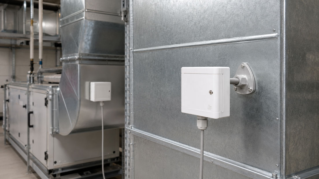
Humidity measurement in ventilation ducts is an important part of modern HVAC systems, building automation, air conditioning systems, cleanrooms, production areas and plant rooms. It helps to reliably monitor indoor climate, energy consumption, condensation risk, air quality and process conditions. At the same time, the measurement is more demanding than it may seem at first glance: a humidity sensor only provides meaningful results when installation position, airflow, temperature, sensor condition and signal evaluation fit together.
Many measurement errors are not caused by a defective sensor, but by unfavorable installation conditions. If a duct sensor is installed directly behind a heating coil, close to humidification, in a dead zone, too close to an outdoor air damper or at a point where condensation occurs, the measured value can deviate significantly from the actual condition in the air duct. Dirty filters, dust, aerosols, cleaning agents or incorrect parameterization of the analog output can also lead to implausible humidity values.
This article explains what matters when measuring humidity in ventilation ducts. The focus is on installation position, airflow, duct temperature, sensor contamination, condensation, protective filters, response time, comparative measurement, analog output, Modbus, maintenance and typical errors with humidity sensors and temperature/humidity transmitters in HVAC applications.
Table of contents
- Basics: what does a humidity sensor measure in a ventilation duct?
- Installation position: where the duct sensor should be placed
- Airflow: why dead zones and turbulence are problematic
- Understanding duct temperature, relative humidity and dew point
- Avoiding condensation on the sensor
- Sensor contamination, protective filters and air quality
- Response time: why rapid air changes are not always visible immediately
- Analog output, Modbus and integration into building automation
- Comparative measurement and plausibility check
- Maintenance, drift and regular inspection
- Typical measurement errors with humidity sensors in ventilation ducts
- Practical example: humidity value fluctuates strongly after humidifier
- Which measuring instruments / products are suitable?
- Conclusion: good humidity measurement starts with the right measuring point
- FAQ: frequently asked questions about humidity measurement in ventilation ducts
Basics: what does a humidity sensor measure in a ventilation duct?
A humidity sensor in a ventilation duct usually measures relative humidity. Temperature is often also recorded because humidity values are only meaningful to a limited extent without a temperature reference. In many HVAC applications, humidity and temperature are measured together and transmitted to the building automation system as an analog signal, digital signal or via a communication interface.
Relative humidity describes how saturated the air is in relation to the maximum possible water vapor absorption at the current temperature. Warm air can absorb more water vapor than cold air. Therefore, relative humidity can change even though the absolute amount of water in the air remains the same. This exact relationship often leads to misinterpretations in ventilation ducts.
Example: if air is heated after a heating coil, the relative humidity decreases even though no moisture has been removed. If air is cooled, the relative humidity increases. With further cooling, the dew point can be reached and condensation occurs. This is why humidity, temperature and dew point should be considered together in many applications.
A humidity sensor therefore does not simply provide an isolated comfort value. It describes the humidity condition of the air exactly at the point where it is installed. Whether this measured value is representative for the room, the process, the cleanroom, the exhaust air duct or the control system depends strongly on installation location, air mixing, temperature distribution and system condition.
| Measured variable | Meaning | Why important in the ventilation duct? |
|---|---|---|
| Relative humidity | Moisture content relative to the current air temperature | Important control value for HVAC, indoor climate, comfort and processes. |
| Temperature | Thermal condition of the air | Directly influences relative humidity and condensation risk. |
| Dew point | Temperature at which water vapor condenses | Helps avoid condensation in the duct, on components or on the sensor. |
| Absolute humidity | Actual amount of water in the air | Relevant for process air, drying, balancing and dehumidification. |
| Output signal | Transmission of the measured value to the controller or control system | Scaling and signal type must match the building automation system. |
Installation position: where the duct sensor should be placed
The installation position is one of the most important factors for reliable humidity measurement in a ventilation duct. The sensor should be positioned where the air is well mixed and the measured value represents the desired condition. A measuring point directly behind a humidifier, heating coil, cooling coil, outdoor air damper, recirculation damper, silencer or filter can deliver unsuitable values depending on the flow situation.
Directly behind a humidifier, the air is often not yet fully mixed. Humidity gradients, droplets, aerosols or local saturation zones can occur. A sensor at this point can display values that are too high or fluctuate strongly. Behind a heating coil, the temperature distribution may still be uneven, causing the relative humidity to appear locally different than later in the duct run.
An ideal measuring point is often located at a sufficient distance from disturbances and in stable airflow. The sensor should protrude into the duct far enough so that it does not only measure near the wall or in a local edge flow. At the same time, it must remain accessible so that the filter, sensor element and connection can be checked or maintained later.
In large ducts, mixed air chambers or uneven flow conditions, a single measuring point cannot always represent the entire cross-section. In such cases, it must be checked whether a different position, a longer probe version, several measuring points or a comparative measurement are useful. Especially in cleanrooms, laboratories or process air systems, the measuring point should not only be practical, but also technically justified from a measurement point of view.
| Installation location | Typical risk | Recommendation |
|---|---|---|
| Directly behind humidifier | Droplets, aerosols, local supersaturation, strong fluctuations | Plan sufficient mixing distance and avoid condensation. |
| Directly behind heating coil | Uneven temperature distribution | Select measuring point only after stable temperature distribution. |
| Directly behind cooling coil | Condensation, droplet carryover, local humidity peaks | Ensure separation and a dry measuring point. |
| Near duct wall | Edge flow, thermal bridges, wall temperature influences measured value | Insert probe sufficiently into the airflow. |
| Well-mixed duct section | Usually more representative measurement | Preferred position for control and monitoring. |
Airflow: why dead zones and turbulence are problematic
A humidity sensor in a ventilation duct requires representative airflow. If the sensor is located in a dead zone, the air at the sensor element is exchanged only slowly. The measured value then reacts sluggishly or does not reflect the actual condition in the main airflow. Such flow zones can occur especially in large ducts, after bends or in areas with internal components.
Strong turbulence can also be problematic. Although it causes air exchange, it can create locally strongly fluctuating values if different air streams are not yet fully mixed. This is relevant, for example, with mixed air from outdoor air and recirculated air, after humidification or behind cooling coils.
Air velocity also influences response time. With sufficient airflow, the air at the sensor element is exchanged more quickly. With very low air movement, the sensor reacts more slowly. With very high airflow, it must be ensured that the probe, protective filter and mounting are mechanically suitable and that the sensor is not stressed by droplets or particles.
The measuring point should therefore always be considered in relation to the duct geometry. Pipe bends, dampers, fans, filters, coils, silencers and branches influence the flow profile. Incorrect humidity measurement is often less a sensor problem than a measuring point problem.
Understanding duct temperature, relative humidity and dew point
Humidity and temperature are closely linked in the ventilation duct. Relative humidity depends directly on the air temperature. When air is heated, relative humidity decreases with the same amount of water vapor. When air is cooled, it increases. If the temperature falls below the dew point, moisture condenses on cold surfaces or components.
These relationships are particularly important when humidity values are used for control. A sensor upstream of a heating coil measures a different relative humidity than a sensor downstream of the heating coil, even though the absolute humidity does not necessarily have to change. It should therefore be clear which humidity variable is relevant for the specific task.
For comfort control and indoor climate, the relative humidity in the room or supply air area is often decisive. For dehumidification, drying or condensation protection, however, dew point or absolute humidity can be more meaningful. In cleanrooms or process air systems, the stability of humidity within narrow limits may also be important.
The temperature at the sensor element should correspond as closely as possible to the air temperature. Thermal bridges, sunlight on duct walls, poorly insulated ducts or installation near hot components can influence the local temperature. This also distorts the humidity value because the sensor always measures in its own temperature environment.
| Situation | Effect on relative humidity | Practical meaning |
|---|---|---|
| Air is heated | Relative humidity decreases | No moisture removal required, although RH is displayed lower. |
| Air is cooled | Relative humidity increases | Condensation risk increases. |
| Dew point is undershot | Water vapor condenses | Sensor, duct or components can become wet. |
| Sensor is warmer than air | Relative humidity tends to be displayed lower | Avoid heat influence at the installation location. |
| Sensor is colder than air | Relative humidity tends to be displayed higher | Condensation on the sensor is possible. |
Avoiding condensation on the sensor
Condensation is one of the most common causes of incorrect or unstable humidity measurements in ventilation ducts. If water accumulates on the sensor element, protective filter or in the probe tube, the measured value can rise sharply, react sluggishly or remain implausible for a long time. Areas behind cooling coils, after humidifiers, with cold outdoor air portions or in poorly insulated ducts are particularly critical.
A humidity sensor should not be operated permanently in a condensing environment unless it is explicitly designed for this. Even if a sensor works again after drying, repeated condensation can impair long-term stability or increase contamination in the filter. Water can also bind particles and form a layer that changes the response behavior.
The best measure is a suitable measuring point. The sensor should be installed where no droplets, spray mist or local supersaturation occur. In applications with a condensation risk, the dew point should also be considered. If the duct wall or sensor housing is colder than the air, condensation can occur locally even though the main airflow still appears uncritical.
The installation position can also play a role. Depending on the sensor design, condensate should be prevented from running into the probe tube or onto the sensor element. Protective filter, probe orientation and maintenance access should be selected so that moisture can drain or dry off and the sensor is not unnecessarily stressed.
Sensor contamination, protective filters and air quality
Humidity sensors in ventilation ducts are continuously exposed to the air quality in the duct. Dust, fibers, aerosols, oil mist, cleaning chemicals, disinfectants, process vapors or particles can stress protective filters and sensor elements. Even if the sensor is electrically working correctly, a contaminated protective cap can extend the response time or falsify the measured value.
A protective filter protects the sensor element from mechanical stress and contamination. At the same time, every filter acts as an additional barrier between airflow and sensor. A clean and suitable filter is therefore important. If the filter is clogged, the sensor reacts more slowly. If the filter is unsuitable, particles, droplets or aggressive components can damage the sensor element.
In normal HVAC systems, the load is often moderate if the air filtration works. In process air, exhaust air, production areas or cleanrooms, the requirements can vary greatly. It should therefore be checked whether a special filter, a different sensor position or a regular maintenance strategy is required.
It is also important not to damage the sensor during cleaning work in the duct. Mechanical cleaning, compressed air, water, solvents or direct contact with the sensor element can be problematic. Maintenance should therefore be carried out and documented according to the manufacturer’s instructions.
Response time: why rapid air changes are not always visible immediately
Response time describes how quickly a humidity sensor reacts to a change in air humidity. It depends on the sensor element, protective filter, air velocity, temperature, installation position and condition of the sensor. A sensor may react quickly in a laboratory test, but appear significantly slower in the real duct if the airflow is unfavorable or the filter is contaminated.
Response time is particularly important for control tasks. If the sensor reacts too slowly, humidification or dehumidification may be adjusted too late. This can lead to overshoot, unstable control or unnecessary energy consumption. Conversely, a very fast sensor in poorly mixed air can show strong fluctuations that must be damped from a control engineering point of view.
The measured humidity can also lag behind the real process change in time. After switching on a humidifier, after a damper change or after load changes in the room, it takes time for the air in the duct to mix and for the sensor to see a stable condition. Not every delay is therefore a sensor fault.
For stable measured values, sensor position, probe design, protective filter and controller parameters should be considered together. In building automation, it can be useful to filter or average measured values. However, filtering must not be so strong that relevant humidity changes are detected too late.
| Influence on response time | Effect | Practical consequence |
|---|---|---|
| Protective filter | Delays air exchange at the sensor element | Clogged filters lead to sluggish measurement. |
| Air velocity | Determines air exchange at the sensor | Dead zones cause slow or implausible response. |
| Temperature change | Sensor and air must thermally equalize | Humidity value may be temporarily delayed or shifted. |
| Contamination | Obstructs moisture transport to the sensor element | Measured value reacts slowly or drifts. |
| Software filtering | Smooths measured value in controller or transmitter | Can calm fluctuations, but delay real changes. |
Analog output, Modbus and integration into building automation
Humidity sensors and temperature/humidity transmitters are often integrated directly into building automation systems in HVAC plants. Typical output signals are 0–10 V, 4–20 mA or digital interfaces such as Modbus. Which signal type is suitable depends on the existing controller, cable length, interference environment, number of measured values and diagnostic requirements.
A 0–10 V signal is widely used in building automation and easy to evaluate. It is well suited for many applications with manageable cable lengths and a suitable input card. A 4–20 mA signal is more robust against voltage drops and is often used when longer cables, industrial environments or clear fault detection via current signal are desired.
With digital interfaces such as Modbus, several values can be transmitted, for example relative humidity, temperature, dew point or status information. This reduces wiring effort and facilitates the integration of multiple measured variables. At the same time, address, baud rate, data format, register assignment and data point description must be parameterized correctly.
For 4–20 mA signals, scaling is particularly important. It must be clearly defined which humidity range corresponds to 4 mA and which corresponds to 20 mA. If a sensor outputs 0…100 % RH but the controller expects 0…80 % RH, all values are displayed incorrectly. The UPS4E loop calibrator is suitable for testing such current signals. It can be used to measure or simulate current loops and detect scaling errors between sensor, display, PLC and building management system.
| Signal type | Typical use | What to pay attention to? |
|---|---|---|
| 0–10 V | Building automation, short to medium cable lengths | Check voltage drop, reference potential and scaling. |
| 4–20 mA | Robust analog transmission, longer cables | Design load, supply, fault current and measuring range correctly. |
| Modbus | Digital transmission of multiple measured values | Document address, registers, baud rate and data format. |
| Relay / limit value | Simple alarm or switching function | Select hysteresis and switching point to match the process. |
| Handheld measuring instrument / comparison | Plausibility check on site | Keep measuring point and measuring conditions comparable. |
Comparative measurement and plausibility check
If a humidity value appears implausible, the sensor should not be replaced immediately. A comparative measurement often helps distinguish sensor faults from installation or system problems. This is done using a suitable reference or handheld measuring instrument at the same or as comparable a location as possible.
It is important that the comparative measurement is truly comparable. A handheld measuring instrument at an inspection opening may not measure the same air condition as a permanently installed duct sensor further inside the duct. Temperature differences, airflow, waiting time and measuring position also influence the comparison. The reference probe should be given sufficient time to acclimatize.
In large ducts or with strongly uneven air distribution, it may be useful to check several measuring points across the cross-section. If the values vary strongly, the duct sensor is not necessarily wrong. The air at the measuring point may simply not be representatively mixed.
A plausibility check should consider humidity, temperature and system condition together. Is the humidifier running? Is the cooling coil active? Are damper positions plausible? Is there condensation? Has the filter been replaced? Do sensor value and room value correspond to each other? Such questions help narrow down the cause in a targeted way.
Maintenance, drift and regular inspection
Humidity sensors are subject to aging and possible drift depending on operating conditions. Long-term stability depends on sensor principle, air quality, temperature, humidity load, condensation, contamination and chemical exposure. In normal HVAC applications, requirements may be moderate; in cleanrooms, laboratories or production environments, regular checks can be much more important.
Maintenance includes visual inspection of the sensor, protective filter, connection cable and housing. Contaminated filters should be cleaned or replaced according to specifications. The sensor element must not be mechanically damaged. The tightness of the duct connection and accessibility of the measuring point should also be checked.
Regular comparative measurements help detect drift or installation problems at an early stage. If a sensor systematically deviates from a reference over a longer period of time, it should be checked whether cleaning, recalibration or replacement is required. In quality-relevant systems, a documented calibration strategy may be necessary.
Maintenance should not only be reactive. If humidity values are relevant for energy efficiency, cleanroom quality, storage conditions or process safety, inspection intervals and permissible deviations should be defined. Only then does humidity measurement remain reliable in the long term.
Typical measurement errors with humidity sensors in ventilation ducts
Many typical error patterns can be traced back to a few causes. Often the sensor is installed at a non-representative point. It then displays a real humidity value, but not the value that the control system actually needs. Temperature differences between the sensor environment and airflow are also common and shift the relative humidity value.
Another common error is condensation. If the sensor becomes wet with condensation, the measured value rises sharply and often remains high for longer until the filter and sensor element have dried again. Contamination can also falsify the measurement, especially if the filter or sensor cap is clogged.
When integrating into building automation, errors occur due to incorrect signal type, incorrect scaling, reversed terminals, incorrect Modbus registers or unsuitable software filtering. In this case, the sensor itself works correctly, but the displayed value is wrong or reacts unusually.
Troubleshooting should therefore always be systematic: check the measuring point, assess the system condition, inspect the sensor condition, perform a comparative measurement and only then check signal processing and parameterization. This avoids replacing a sensor even though the actual problem lies in the installation or control system.
| Error pattern | Possible cause | Test approach |
|---|---|---|
| Humidity value permanently too high | Condensation, wrong position after humidifier, cold sensor | Check dew point, installation location and sensor condition. |
| Humidity value permanently too low | Sensor too warm, incorrect scaling, contaminated sensor | Check temperature at the sensor and output signal. |
| Measured value reacts very slowly | Clogged filter, dead zone, low air velocity | Check filter, airflow and installation position. |
| Measured value fluctuates strongly | Incomplete air mixing, droplets, turbulence or control overshoot | Evaluate mixing distance, humidifier operation and controller parameters. |
| Value in BMS/PLC does not match sensor | Incorrect scaling, terminal error, wrong register | Check analog signal or Modbus data point separately. |
Practical example: humidity value fluctuates strongly after humidifier
In a ventilation system, a duct sensor is used to control the supply air humidity. After commissioning, the measured value shows strong fluctuations. The building automation system constantly readjusts the humidifier, causing the humidity in the room to temporarily appear too high and then too low. The sensor is initially suspected as a possible source of error.
During inspection, it becomes clear that the sensor is mounted very close behind the humidifier. At this point, the air is not yet sufficiently mixed. In addition, fine droplets or local humidity peaks occasionally reach the sensor element. The sensor is therefore not measuring incorrectly; it is measuring a strongly fluctuating local condition at an unsuitable point.
After relocating the measuring point to a better mixed duct section and adjusting the controller damping, the measured value becomes significantly more stable. A comparative measurement confirms that the new measuring location better matches the condition of the supply air. In addition, the protective filter is checked and a maintenance interval is defined.
The example shows: when measuring humidity in a ventilation duct, the measuring point is often more important than pure sensor accuracy. Only when airflow, temperature, humidification, condensation risk and signal evaluation fit together does the humidity sensor provide a reliable control value.
Which measuring instruments / products are suitable?
The category humidity sensors / dew point sensors is the right starting point when relative humidity, temperature or dew point are to be recorded in HVAC, building, laboratory or process applications. For ventilation ducts, duct sensors or temperature/humidity transmitters are particularly relevant.
For HVAC applications, humidity and temperature sensors for HVAC applications with digital output signal are suitable. This design is particularly interesting when humidity and temperature are measured together and integrated into building automation via analog output signals or digital interfaces.
The category humidity measuring instruments / humidity sensors offers a broader overview of devices for humidity measurement, including room and duct transmitters, process probes, handheld measuring instruments, data loggers and references for calibration or validation. This allows stationary measurement and mobile comparative measurement to be combined effectively.
If humidity sensors with 4–20 mA output are integrated into PLCs, BMS or data loggers, the UPS4E loop calibrator is helpful. It can be used to check whether output signal, scaling and display in the control system match correctly.
| Product / area | Typical use | Particularly relevant for |
|---|---|---|
| Humidity sensors / dew point sensors | Stationary measurement of humidity, temperature and dew point | HVAC, ventilation ducts, cleanrooms, process air, dew point monitoring and building automation |
| Humidity and temperature sensors for HVAC applications | Duct and room humidity measurement with analog or digital output | Building automation, ventilation systems, air conditioning systems and BMS connection |
| Humidity measuring instruments / humidity sensors | Selection of stationary and mobile humidity measurement technology | Comparative measurement, data logging, process control and validation |
| Temperature/humidity transmitters | Conversion of humidity and temperature values into process signals | 0–10 V, 4–20 mA, Modbus, BMS and PLC inputs |
| UPS4E loop calibrator | Testing and simulation of 4–20 mA signals | Commissioning, scaling check, troubleshooting and signal comparison |
Conclusion: good humidity measurement starts with the right measuring point
Humidity measurement in ventilation ducts is an important component for HVAC, building automation, air conditioning systems, cleanrooms and process air applications. Reliable measured values, however, are not achieved by a precise sensor alone. The decisive factors are installation position, airflow, temperature distribution, protection against condensation, clean filter, suitable response time and correct signal evaluation.
Many typical measurement errors are caused by unfavorable measuring points or incorrect interpretation of relative humidity. A sensor directly behind a humidifier, heating coil or cooling coil often does not measure a representative condition. Condensation, contamination and incorrect scaling in building automation can also lead to implausible values.
The most important recommendation is: always consider humidity sensors in ventilation ducts as a complete measuring point. Sensor, probe position, air routing, temperature, dew point, output signal, control system and maintenance must fit together. Only then does humidity measurement provide stable values for control, comfort, energy efficiency and process safety.
FAQ: frequently asked questions about humidity measurement in ventilation ducts
Where should a humidity sensor be installed in a ventilation duct?
The sensor should be installed at a point with well-mixed air and representative airflow. Direct proximity to humidifiers, heating coils, cooling coils, dampers or dead zones should be avoided.
Why is the installation position so important?
The sensor only measures the condition at its installation point. If the air there is not representatively mixed, the sensor may be locally correct, but unsuitable for control or evaluation.
What does a humidity sensor in the duct measure?
It usually measures relative humidity. Temperature is often also recorded. Depending on the device, dew point or other humidity variables can also be calculated from this.
Why must temperature also be measured?
Relative humidity depends strongly on temperature. Without temperature reference, a humidity value can be misinterpreted, especially during heating or cooling processes in the air duct.
What is the dew point?
The dew point is the temperature at which air is saturated with water vapor and condensation begins. It is important for detecting condensation risks in the duct or on the sensor.
Why is condensation on the sensor problematic?
Condensation can greatly increase the measured value, extend the response time and stress the sensor or protective filter. Repeated condensation can impair long-term stability.
How can condensation on the humidity sensor be avoided?
The measuring point should be outside areas with droplets, spray mist and local supersaturation. Dew point, duct temperature, insulation and installation position should also be considered.
Why does a duct sensor sometimes react slowly?
Causes can include low air velocity, dead zones, contaminated filters, protective caps, temperature equalization or software filtering in the controller.
What role does the protective filter play?
The protective filter protects the sensor element from particles and mechanical stress. If it is contaminated, the sensor can react more slowly or display incorrect values.
How often does a humidity sensor need maintenance?
This depends on air quality, application, accuracy requirement and system environment. In contaminated process air or quality-relevant systems, regular visual inspections and comparative measurements are useful.
How do you check whether a humidity sensor measures correctly?
A comparative measurement with a suitable reference or handheld measuring instrument helps. Measuring point, waiting time, temperature and airflow must be comparable.
Why do room humidity and duct humidity not always match?
Temperature changes, mixed air, humidification, dehumidification or different air conditions can exist between room and duct. Measuring location and control task must therefore fit together.
Which output signals are common?
0–10 V, 4–20 mA or digital interfaces such as Modbus are common. The suitable signal type depends on building automation, cable length, interference environment and desired diagnostics.
What must be considered with 0–10 V?
For voltage signals, cable length, reference potential, voltage drop and scaling should be checked. For many HVAC applications, 0–10 V is common and well suited.
When is 4–20 mA useful?
4–20 mA is useful with longer cables, industrial environments or when a robust current signal with clear scaling is desired.
When is Modbus useful?
Modbus is useful when several measured values such as humidity, temperature, dew point and status are to be transmitted digitally. Address, baud rate and registers must be documented correctly.
Why does the BMS show a different value than the sensor?
Possible causes include incorrect scaling, wrong input type, reversed terminals, incorrect Modbus registers or software filtering in the building automation system.
Which products are suitable for humidity measurement in ventilation ducts?
Humidity sensors, dew point sensors and temperature/humidity transmitters for HVAC applications are suitable. The right probe design, protective filter, output signal and installation position are important.