


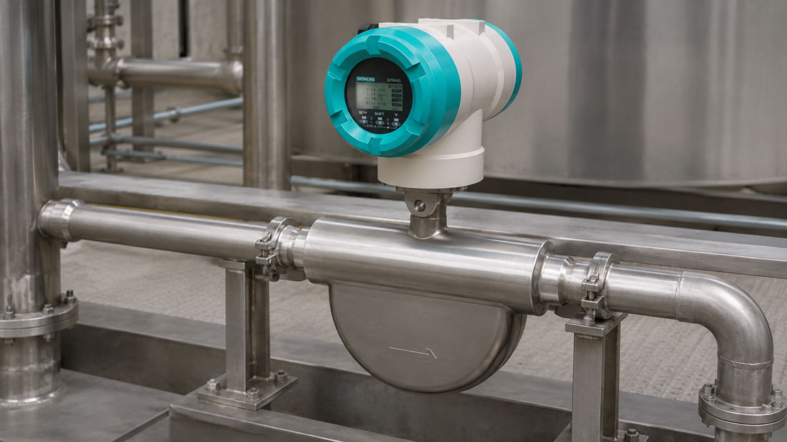
A Coriolis flowmeter may indicate a small positive or negative mass flow even when the process appears to be at a standstill. In practice, a zero adjustment is then often started immediately.
However, this is not always the correct response. A displayed flow with the process shut off may be caused by the actual zero point of the measuring instrument. Other possible causes include a valve that does not close completely, thermal flow, gas bubbles, vibrations or a measuring tube that is only partially filled.
If the zero point is adjusted under unsuitable conditions, the instrument stores an actual flow or process disturbance as the new zero value. The display may then appear correct at standstill, while the measured values during operation are systematically shifted.
A zero adjustment is therefore not a general repair function. It is a precise adaptation of the Coriolis measuring system to its installation and process conditions and may only be performed when a demonstrably stable zero-flow condition exists.
Table of contents
- What happens during zero adjustment
- When zero adjustment is useful
- When zero adjustment should not be performed
- Requirements for a reliable zero point
- Correctly establishing zero flow using shut-off valves
- How to perform zero adjustment correctly
- Why a value may still be indicated at zero flow
- Systematic checks before adjustment
- Distinguishing zero adjustment from low-flow cut-off
- Typical errors during zero adjustment
- Practical example: Apparent zero-point error in a dosing system
- Which measuring instruments / products are suitable?
- Conclusion
- Frequently asked questions about Coriolis zero adjustment
What happens during zero adjustment
A Coriolis flowmeter excites its measuring tubes at a defined vibration. When mass flows through the tubes, a measurable phase shift occurs. The transmitter uses this change to calculate the mass flow.
Even at genuine zero flow, a very small residual signal may be present. Possible causes include mechanical stress from the pipeline, mounting orientation, process pressure, temperature and external vibrations.
During zero adjustment, the transmitter records the signal under defined zero-flow conditions. The calculated offset is stored and taken into account during subsequent flow calculation.
The adjustment therefore does not alter the actual factory calibration of the sensor. It adapts the zero point to the specific installation.
The zero point is particularly relevant at low flow rates. A constant offset of, for example, 0.2 kg/h is hardly significant at a process flow of 1,000 kg/h. For a dosing flow of 1 kg/h, however, the same error would be considerable.
When zero adjustment is useful
Zero adjustment may be useful or specified by the manufacturer particularly in the following situations:
- after initial installation and commissioning
- after replacement of the sensor or transmitter
- after significant changes to the pipeline, support or mounting orientation
- after work that has altered mechanical stresses
- at very low flow rates or in demanding dosing applications
- if a zero-point test reveals a relevant and reproducible deviation
- if the operating instructions for the specific instrument require adjustment
A new zero adjustment is normally not required after a standard power interruption because the stored value is retained.
Regularly repeated adjustment without a specific reason is also not automatically useful. A stable Coriolis flowmeter should not be readjusted as a precaution during every maintenance procedure.
When zero adjustment should not be performed
A zero adjustment should not be started while the cause of an unstable indication remains unclear.
The following situations are particularly problematic:
- The shut-off valve does not close completely.
- The measuring tube is empty or only partially filled.
- The medium contains air or gas bubbles.
- The temperature is still changing significantly.
- The pump, pipeline or neighbouring machinery produces strong vibrations.
- The medium is not homogeneous or is in a two-phase condition.
- The process pressure decreases during adjustment.
- The indication fluctuates strongly and does not form a stable average value.
Under these conditions, the transmitter would not record its actual zero point, but merely a snapshot of the disturbance.
Zero adjustment is also not the correct measure if only small fluctuating values are to be suppressed. For this purpose, a low-flow cut-off may be used, provided that this is permissible for the process.
Requirements for a reliable zero point
Before adjustment, the conditions should correspond as closely as possible to those under which the instrument will subsequently operate.
Completely filled measuring tubes
The measuring tubes must be completely filled with a homogeneous medium. Adjustment with an empty or partially filled sensor is not permissible in normal liquid applications.
Gas bubbles alter the density, damping and vibration behaviour of the measuring tubes. They can therefore cause both an unstable zero point and an incorrect mass-flow value.
Actual zero flow
No medium may flow through the sensor. Even a small valve leak can shift the stored zero point.
With liquids, natural circulation, gravity flow and temperature differences must also be considered. These effects can cause a small flow even when the pump is not operating.
Stable temperature and stable pressure
The sensor should be as close as possible to its subsequent operating conditions. This applies in particular to the medium temperature, process pressure and density condition.
After cleaning, steam sterilisation or a major temperature change, sufficient time must be allowed for stabilisation.
Stable mechanical conditions
No strong pump pulsations, valve shocks or vibrations from neighbouring machinery should occur during adjustment.
Pipeline stresses can also influence the zero point. The sensor must not be used to pull poorly aligned pipelines together mechanically.
Correctly establishing zero flow using shut-off valves
Ideally, suitable shut-off valves are installed upstream and downstream of the Coriolis sensor. This allows the sensor to remain completely filled and enclosed under process pressure.
With liquids, a homogeneous flow is often established first in order to flush air or gas out of the measuring tube. The flow is then stopped in accordance with the manufacturer’s instructions.
Closing the downstream valve can help keep the sensor filled and pressurised. The upstream side can then also be shut off. However, the exact sequence depends on the installation, pump concept and operating instructions.
A pump must not be operated against a closed valve if it is not designed for this condition. A bypass line may be required.
After closing the valves, sufficient time should be allowed for the pressure, temperature and measured value to stabilise. An adjustment started immediately after rapid valve closure may still capture pressure shocks and residual oscillations.
How to perform zero adjustment correctly
The exact menu path varies depending on the transmitter. However, the basic procedure is comparable:
- Check the measuring point: Inspect the sensor, pipeline and shut-off valves for correct installation.
- Flush the sensor: Completely fill the measuring tubes with homogeneous medium and remove any gas bubbles.
- Establish operating conditions: Stabilise the temperature, pressure and condition of the medium.
- Establish zero flow: Close suitable valves in accordance with the plant and manufacturer instructions.
- Allow the system to settle: Wait until flow and mechanical vibrations have subsided.
- Start zero adjustment: Run the automatic zero adjustment via the display, software or control system.
- Assess the result: Check the offset, standard deviation and diagnostic messages.
- Restore measuring operation: Open the valves in a controlled manner and verify the measured value under actual process conditions.
Many Coriolis transmitters calculate a standard deviation in addition to the offset during the adjustment. A high or unstable value indicates that the zero-flow conditions were not sufficiently stable.
A successfully completed menu function therefore does not automatically mean that the adjustment was performed under ideal process conditions. The stored value should be checked for plausibility and documented.
Why a value may still be indicated at zero flow
A small displayed flow does not necessarily indicate a defective sensor.
| Possible cause | Typical behaviour | Check |
|---|---|---|
| Valve leakage | Relatively stable flow in one direction | Close a second valve or isolate the line by another suitable method |
| Gas bubbles or two-phase flow | Unstable flow and density values | Check density, tube filling, pressure and degassing |
| Mechanical vibration | Fluctuating indication despite closed valves | Temporarily stop the pump and neighbouring machinery |
| Thermal circulation | Small flow caused by temperature differences | Stabilise the temperature and shut off both sides |
| Partially filled measuring tube | Unstable values and implausible density | Check the mounting orientation and complete tube filling |
| Actual zero-point offset | Small reproducible value under stable conditions | Verify the zero point and adjust it if necessary |
Density measurement is particularly useful during troubleshooting. A strongly fluctuating or implausible density value is often more indicative of gas content or incomplete tube filling than of a pure zero-point error.
Systematic checks before adjustment
Before storing a new zero point, the current deviation should be investigated under reproducible conditions.
- Document the current mass flow, density and temperature.
- Check whether the system is actually completely shut off.
- Close a second valve if this can be done safely.
- Observe whether the pressure drops between the closed valves.
- Exclude gas bubbles, cavitation and two-phase conditions.
- Temporarily stop the pump and nearby vibration sources.
- Wait until the temperature and indication are stable.
- Evaluate the available zero-point or diagnostic function.
If the indicated flow disappears after a second valve is closed, an actual flow was probably passing through the first valve. A zero adjustment would have been incorrect in this case.
If a small value remains under reproducible and stable zero-flow conditions, a field zero adjustment may be appropriate.
Distinguishing zero adjustment from low-flow cut-off
Zero adjustment and low-flow cut-off perform different functions.
Zero adjustment corrects a constant offset of the measuring system at genuine zero flow.
The low-flow cut-off sets measured values below a configured threshold to zero. For example, it prevents very small fluctuations at standstill from changing the totaliser reading.
However, if the cut-off is set too high, genuine process flow may be suppressed. This is particularly critical in:
- very small dosing applications
- leak monitoring
- slow filling processes
- high-viscosity media
- processes with a wide measuring range
The low-flow cut-off must therefore not be used to conceal an unexplained measuring error.
Typical errors during zero adjustment
| Error | Possible consequence | Better approach |
|---|---|---|
| Adjustment performed with a leaking valve | Actual flow is stored as the zero point | Verify zero flow using two shut-off points |
| Measuring tube not completely filled | Unstable or significantly shifted zero point | Fill and vent the sensor completely |
| Adjustment performed immediately after a temperature change | The thermal transition is included in the adjustment | Allow sufficient stabilisation time |
| Gas bubbles in the medium | Fluctuating density and incorrect offset | Improve process pressure and degassing |
| Strong vibration during adjustment | High standard deviation and unstable zero point | Eliminate the vibration source or improve the installation |
| Zero point overwritten regularly without a reason | Long-term changes are concealed | Document the previous value and adjust only when justified |
| Low-flow cut-off confused with zero adjustment | Genuine low flow rates are suppressed | Configure and test both functions separately |
Practical example: Apparent zero-point error in a dosing system
A Coriolis flowmeter monitors the dosing of a liquid additive. After the dosing valve is closed, the instrument continues to indicate approximately 0.8 kg/h.
Because the normal dosing flow is only 25 kg/h, a zero adjustment is initially planned.
Before the adjustment, the process is examined in more detail. The indication is relatively stable and always points in the same flow direction. The totaliser also continues to increase slowly.
After a second shut-off valve is additionally closed, the measured value drops to almost zero. This proves that the sensor had previously been detecting an actual flow.
Inspection of the dosing valve reveals deposits on the sealing surface. The valve therefore does not close completely.
After cleaning, the measured value remains stable within the expected zero range when the valve is closed. A new zero adjustment is not required.
If the technician had stored the original flow of 0.8 kg/h as the zero point, the subsequent dosing measurement would have been shifted by the same amount across the entire measuring range.
Which measuring instruments / products are suitable?
The Coriolis and vortex flowmeters category contains measuring systems for liquids, gases and steam. Coriolis instruments measure mass flow directly and, depending on the version, additionally provide density, temperature and calculated volume flow.
Additional measuring principles and accessories can be found in the flow measurement technology category.
SITRANS FC120/140 for low flow rates
The SITRANS FC120/140 are designed for precise measurement of low flow rates.
At low flow rates in particular, a zero-point offset has a much greater percentage effect. Correct installation and carefully performed zero adjustment are therefore especially important in such applications.
SITRANS FC520/540 for standard and hygienic applications
The SITRANS FC520/540 are suitable for a wide range of industrial and hygienic applications.
After cleaning, sterilisation or product changeover, it must be ensured before zero adjustment that the sensor is again completely filled, free from gas bubbles and thermally stable.
SITRANS FCT040 transmitter
The SITRANS FCT040 processes the sensor signals from SITRANS FC Coriolis systems and provides diagnostic, configuration and measurement functions.
The transmitter can be used to evaluate process values, diagnostic messages and zero-point settings, among other functions. The exact procedure depends on the sensor, firmware and instrument version.
Selection and commissioning
At least the medium, flow range, density, viscosity, temperature, pressure, pipe connection and required accuracy are needed to select a Coriolis measuring system.
ICS Schneider Messtechnik assists with product selection, sizing and commissioning. In the event of zero-point problems, information about the mounting orientation, valve arrangement, tube filling, pump technology and the behaviour of mass flow, density and temperature should also be provided.
Conclusion: Check the cause first, then change the zero point
Zero adjustment can adapt the accuracy of a Coriolis flowmeter to the actual installation and process conditions. It is particularly relevant during initial commissioning, after mechanical changes and at low flow rates.
The requirements are completely filled measuring tubes, a homogeneous medium condition, absolute zero flow and stable pressure, temperature and vibration conditions.
A displayed flow with closed valves is not automatically a zero-point error. Valve leakage, gas bubbles, thermal circulation and external vibrations must be excluded first.
An adjustment performed under incorrect conditions can distort the measurement more severely than the original offset. The previous and new zero-point values, as well as the stability determined during adjustment, should therefore be documented.
Low-flow cut-off is not a substitute for a correct zero point. It may only be configured in such a way that genuine low flow rates are not lost.
The most important rule is therefore: A zero adjustment is not performed merely to make the display show zero, but only when a genuine and stable zero-flow condition has been clearly verified.
Frequently asked questions about Coriolis zero adjustment
Does a Coriolis flowmeter need to be adjusted during every commissioning?
The manufacturer’s specifications for the specific instrument are decisive. A field zero adjustment is often recommended after installation in order to account for installation, pressure and temperature influences.
Must the sensor be filled during zero adjustment?
In normal liquid applications, the measuring tubes must be completely and homogeneously filled with medium. Adjustment with an empty or partially filled sensor leads to incorrect results.
May a small flow still be present during zero adjustment?
No. Even very small actual flow rates can be stored as an offset and subsequently shift all measured values.
Why does the Coriolis meter still indicate flow when the valve is closed?
Possible causes include valve leakage, thermal circulation, gas bubbles, vibrations, incomplete tube filling or an actual zero-point offset.
How can valve leakage be identified?
If possible, a second valve is closed. If the indicated flow then disappears, the first valve was probably not shutting off completely.
Why must the temperature be stable?
Temperature changes affect the sensor, medium and mechanical stresses. Adjustment during a thermal transition can therefore store a non-representative zero point.
What does a high standard deviation during zero adjustment mean?
It indicates unstable conditions such as residual flow, gas bubbles or mechanical vibrations. The cause should be eliminated and the adjustment repeated.
Is low-flow cut-off the same as zero adjustment?
No. Zero adjustment corrects an offset. Low-flow cut-off sets measured values below a defined threshold to zero.
Can an incorrect zero adjustment be reversed?
Depending on the transmitter, a previous, factory-set or manually documented value may be entered again. The exact procedure depends on the instrument version.
When is the zero point particularly critical?
At low flow rates, in dosing and filling applications and in applications with a wide measuring range, a constant zero-point offset has a particularly strong percentage effect.