


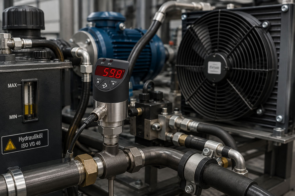
A fan switches on, turns off again a few seconds later and shortly afterwards switches on once more. A compressor starts and stops constantly even though the process temperature hardly appears to change. Or a heating element is continuously switched on and off around the configured setpoint.
Such cycling does not automatically mean that the temperature switch is defective. Very often, the cause is insufficient hysteresis, an unsuitable switching point, an unfavourable sensor position or thermal inertia of the system that has not been taken into account.
The consequences can be significant: relays and contactors are operated unnecessarily often, compressors and motors start too frequently, valves wear more quickly and temperature control becomes unstable. At the same time, an excessively large deadband can cause the temperature to fluctuate more than is permissible for the process.
Suitable devices can be found under Temperature switches / thermostats. Further solutions for industrial temperature measurement are grouped under Temperature measurement technology.
Table of Contents
- How does a temperature switch work?
- What do hysteresis, switching differential and deadband mean?
- Why does hysteresis prevent frequent switching?
- What happens if the hysteresis is too small?
- Can the hysteresis also be too large?
- Why is the sensor installation position so important?
- Take thermal inertia and residual heating into account
- Consider the response time of the temperature sensor
- Contact load and relay wear
- Minimum run and minimum standstill times
- Correctly switching heating and cooling
- Measurement fluctuations and electrical interference
- Distinguishing between control thermostats and safety temperature limiters
- Typical fault patterns
- Recommended procedure for configuration
- Correctly testing switching and reset points
- Practical example from a cooling unit
- Which products and solutions are suitable?
- Conclusion
- Frequently asked questions
How does a temperature switch work?
A temperature switch monitors a temperature and changes its electrical switching state when a defined limit is reached.
Depending on the application, this can for example:
- switch on a fan,
- switch off a heater,
- start a cooling unit,
- operate a solenoid valve,
- trigger a warning, or
- shut down a machine in the event of overtemperature
.
The temperature at which the output changes its state is referred to as the switching point.
To prevent the connected device from switching back immediately as soon as the temperature falls slightly below the switching point, there is a second value: the reset point.
The difference between these two temperatures is crucial for stable operation.
What do hysteresis, switching differential and deadband mean?
With temperature switches, the terms hysteresis and switching differential are often used to describe the difference between the switching point and the reset point.
In simplified form:
Hysteresis = |switching point − reset point|
An example:
A fan is intended to switch on at 80 °C and switch off again after cooling to 75 °C.
The hysteresis is therefore:
80 °C − 75 °C = 5 K
Between 75 and 80 °C, the most recently reached switching state is maintained.
The term deadband is also frequently used in this context. In more complex controllers, however, “deadband” can also describe a neutral zone between two separate control actions – for example heating and cooling. When configuring a device, it should therefore always be checked how the respective manufacturer defines the term.
Why does hysteresis prevent frequent switching?
Assume that a fan is intended to limit the temperature of a hydraulic tank to approximately 60 °C.
If the fan switched on at exactly 60.0 °C and switched off again as soon as the temperature fell to 59.9 °C, the following could occur:
- The temperature reaches 60.0 °C.
- The fan switches on.
- The temperature falls slightly to 59.9 °C.
- The fan switches off again.
- Because waste heat is still being generated, the temperature rises again.
- The fan starts again.
This process can repeat continuously.
If, on the other hand, the fan switches on at 60 °C and does not switch off again until the temperature falls to 55 °C, the temperature must change significantly before another switching operation occurs.
This results in more stable control and reduces the number of switching cycles.
What happens if the hysteresis is too small?
A very small switching differential may initially appear attractive because the temperature seems to be maintained particularly precisely around a setpoint.
In a real system, however, even very small normal temperature fluctuations can trigger a new switching operation.
Typical consequences include:
- frequent switching on and off,
- relay or contactor wear,
- frequent compressor starts,
- unstable valve actuation,
- fluctuating process conditions,
- increased mechanical wear, and
- an unnecessarily high number of switching messages in the PLC or control system.
It must also be taken into account that temperature is never completely constant. Changes in flow, load variations, mixing processes and the measurement uncertainty of the sensor already create small fluctuations.
The hysteresis should therefore be larger than the normal short-term fluctuations that are not intended to trigger a new operating state.
Can the hysteresis also be too large?
Yes. Large hysteresis reduces switching frequency but at the same time results in a larger temperature range.
For example:
A heater switches on at 40 °C and does not switch off again until 60 °C.
The hysteresis is 20 K. The system therefore switches relatively infrequently, but the process temperature fluctuates over a wide range.
For simple frost protection or robust machine cooling, a larger deadband may be acceptable. For temperature-critical production processes, the same setting may be unsuitable.
The correct hysteresis is therefore always a compromise between:
- temperature stability,
- switching frequency,
- thermal dynamics, and
- the load capacity of the connected actuators.
Why is the sensor installation position so important?
Even correctly configured hysteresis will perform poorly if the temperature sensor is installed in an unsuitable position.
A typical example is a cooling unit.
If the sensor is located directly in the cold airflow from the evaporator, the measured temperature drops very quickly shortly after cooling is switched on. The thermostat assumes that the entire area being cooled is already cold enough and switches the cooling system off again.
Shortly after shutdown, the cold airflow disappears. The sensor warms up again and the compressor restarts.
The actual room or product temperature may have changed very little during this process.
A similar problem occurs with heating systems if the sensor is installed directly next to the heating element. It detects a high local temperature very quickly even though the rest of the process is still considerably colder.
The measuring point should therefore measure the temperature that is actually intended to be controlled or monitored as representatively as possible.
Take thermal inertia and residual heating into account
A temperature switch cannot stop the thermal energy of a system instantly.
If a heater is switched off at 80 °C, the heating element, pipe wall or heat exchanger may still contain considerable stored heat. The process temperature may therefore initially continue to rise after shutdown.
This behaviour is often perceived as thermal lag or overshoot.
In cooling systems, the opposite effect occurs: even after a compressor or valve has been switched off, cooling capacity may still remain in the system.
When selecting the switching point, the following should therefore be considered:
- How quickly is heat or cooling introduced?
- How large is the thermal mass?
- How quickly does the sensor respond?
- How far does the temperature continue to change after switching?
Hysteresis alone cannot compensate for a fundamentally poorly matched thermal process.
Consider the response time of the temperature sensor
The temperature sensor itself also has thermal inertia.
A small sensor directly exposed to the medium responds considerably faster than a large temperature sensor installed in a thick protective or thermowell assembly.
The more slowly the sensor responds, the later the temperature switch detects an actual process change.
This can mean that the real temperature has already significantly exceeded the intended switching point before the sensor detects that value.
For fast processes, not only the measuring range and accuracy but also the response time of the complete measuring point should therefore be taken into account.
This includes the sensor, thermowell, heat transfer and installation conditions.
Contact load and relay wear
Frequent switching is particularly problematic when the temperature switch directly switches an electrical load.
Mechanical contacts have only a limited electrical and mechanical service life.
Loads with high inrush currents are particularly demanding, for example:
- motors,
- compressors,
- transformers,
- solenoid valves, and
- certain heating loads.
Contact erosion and arcing can occur during switching.
The permissible switching capacity must therefore not be assessed solely on the basis of the normal operating current. Voltage, current, load type and the manufacturer’s specifications for the switching contact must all be taken into account.
For larger loads, it is often advisable for the temperature switch to control only a contactor, relay or PLC input, while the actual power is switched separately.
Minimum run and minimum standstill times
For certain machines, suitable temperature hysteresis alone is not sufficient.
A typical example is a compressor.
Even if the temperature has already reached the switch-on point again, an immediate restart may be technically undesirable. In such applications, additional minimum standstill times are often provided.
Conversely, a minimum run time can prevent a machine from being switched off again only a few seconds after starting.
These timing functions are usually not provided by a simple mechanical thermostat, but by:
- electronic controllers,
- time relays,
- PLC programs, or
- appropriately configurable controllers.
For compressors that continuously short-cycle, the hysteresis should therefore not simply be increased automatically. The intended start/stop logic must also be checked.
Correctly switching heating and cooling
In simple applications, either heating or cooling is controlled.
The situation becomes more complex when both functions are present.
For example, a control cabinet may need to be heated at low temperatures and ventilated at high temperatures.
One possible strategy would be:
- heater ON below 10 °C,
- heater OFF at 15 °C,
- fan ON above 35 °C,
- fan OFF at 30 °C.
Between 15 and 30 °C, both outputs are switched off.
This neutral temperature range is also referred to as a deadband in some controllers.
It is particularly important that the heating and cooling functions do not interfere with one another. Otherwise, incorrect configuration could result in the cooling system starting immediately after the heater is switched off.
Measurement fluctuations and electrical interference
An electronic temperature switch can also switch frequently because of an unstable input signal.
Possible causes include:
- electromagnetic interference,
- poor electrical contacts,
- damaged sensor cables,
- unsuitable cable routing,
- strongly fluctuating flow conditions, or
- an actually unstable process.
Before significantly increasing the hysteresis, it should therefore be checked whether the measured temperature is actually fluctuating.
An additional temperature data logger can be helpful here. If the temperature is recorded over a longer period, it becomes possible to determine whether the switching behaviour follows the real process or is being caused only by the measuring or switching chain.
Distinguishing between control thermostats and safety temperature limiters
Not every temperature switch is intended for normal cyclic temperature control.
A control thermostat can, for example, regularly switch a fan or heater on and off.
A safety temperature limiter, on the other hand, performs a protective function. It is intended to bring the system into a safe state when an impermissible temperature occurs.
With certain versions, manual reset is required after the limiter has tripped. Such a limiter must not simply be treated as a normal two-position controller.
If a safety temperature limiter trips repeatedly, the cause within the process should therefore be investigated.
Simply changing the limit value or bypassing the shutdown would not be an appropriate solution to repeated activation of a safety device.
Typical fault patterns
| Observation | Possible cause | Recommended check |
|---|---|---|
| Switch continuously changes state directly around the setpoint | Hysteresis too small | Check switching and reset points |
| Cooling starts and stops within a few seconds | Sensor located directly in the cold airflow | Check sensor installation position |
| Heating switches off very early | Sensor too close to the heating element | Select a more representative measuring point |
| Temperature overshoots after shutdown | Thermal inertia or stored heat | Check switching point and process dynamics |
| Relay fails after a short operating period | Excessive switching frequency or unsuitable contact load | Check switching cycles, load type and switching capacity |
| Switch responds significantly later than the reference sensor | Slow thermal response time | Check sensor design and installation conditions |
| Electronic switch chatters despite stable process temperature | Possible electrical interference | Check sensor cable and measurement signal |
| Safety temperature limiter trips repeatedly | Actual overtemperature or fault in the control loop | Investigate the cause of the overtemperature |
Recommended procedure for configuration
- Define the control task: Should the system heat, cool, generate an alarm or perform a safety shutdown?
- Determine the required switching point: Define the actual process temperature at which the action should begin.
- Define the reset point: Determine how far the temperature must change before the system switches back.
- Consider process fluctuations: Normal short-term temperature changes must not continuously trigger switching operations.
- Check thermal inertia: Take residual heating or cooling into account.
- Check sensor position: The sensor should measure the relevant process temperature rather than only a local extreme value.
- Consider actuator dynamics: Compressors, motors and valves must not be switched at arbitrarily high frequencies.
- Check contact load: Compare switching capacity and load type with the manufacturer’s specifications.
- Perform a test cycle: Operate the system several times through the switching and reset points.
- Observe switching frequency: Do not evaluate only a single switching operation; observe actual operation over a longer period.
Correctly testing switching and reset points
For a temperature switch, the switching point and reset point should be tested separately.
To do this, the temperature is changed in a controlled manner towards the switching point.
The temperature is documented when the contact actually changes state.
The temperature is then changed in the opposite direction until the switch returns to its original state.
The actual hysteresis can be determined from these two temperatures.
Example:
| Measured variable | Temperature |
|---|---|
| Switching point | 80.3 °C |
| Reset point | 75.1 °C |
| Actual hysteresis | 5.2 K |
It is important not to change the temperature too quickly. Otherwise, the thermal inertia of the reference sensor and device under test, as well as different sensor positions, can distort the result.
For safety- or quality-relevant temperature switches, the test should be carried out and documented in accordance with the specified test procedure or calibration requirements.
Practical example from a cooling unit
An industrial hydraulic power unit uses a temperature switch to control the oil cooler.
The fan is intended to prevent the oil temperature from remaining above 60 °C for extended periods.
After a change to the system configuration, it becomes apparent that the fan sometimes switches on and off several times within a few minutes.
An initial inspection does not reveal any defect in the temperature switch.
The switching point is set to 60 °C, but the reset point has been configured at 59 °C. At the same time, the sensor is located directly downstream of the oil cooler.
When the fan switches on, cooler oil flows past the sensor very quickly. The sensor detects a temperature drop within a short period and switches the fan off again.
At this point, however, the average oil temperature in the tank has hardly changed.
After checking the complete system, two changes are made:
The sensor is repositioned at a location that better represents the relevant oil temperature. At the same time, the reset point is selected so that sufficient hysteresis is created between switching on and switching off.
As a result, the fan runs for significantly longer periods, the number of starts decreases and the average oil temperature still remains within the required range.
The example demonstrates that a frequently switching temperature switch does not necessarily measure incorrectly. Even a correctly functioning switch can cause unstable system operation if it is poorly configured or positioned.
Which products and solutions are suitable?
WIKA TSD-30 – electronic temperature switch with display
The WIKA TSD-30 is particularly suitable for machinery and plant applications in which temperature values need to be displayed locally and switching functions evaluated electronically.
Typical applications include:
- machine tools,
- hydraulic power units,
- cooling and lubrication systems, and
- general machine building.
The local display makes it easier during troubleshooting to compare the current temperature with the switching state.
Electronic temperature switches are particularly useful where flexible configuration and integration into machine control systems are required.
WIKA TCS – mechanical compact temperature switch
The WIKA TCS is a mechanical compact temperature switch for industrial process applications.
An important difference compared with electronic switches is that, in mechanical switches, the switching differential is determined by the design of the switching element and cannot automatically be freely configured via a menu.
Before ordering, it should therefore already be checked whether the switching point, reset behaviour and contact load are suitable for the application.
STW / STB contact safety thermostats
The STW / STB contact safety thermostats demonstrate another important difference: for certain monitoring and safety functions, the switching differential is deliberately defined by the device design.
Such devices should not be selected solely with the objective of achieving the narrowest possible temperature control range. Their intended monitoring or safety function is the decisive factor.
Further electronic and mechanical versions can be found under Temperature switches / thermostats.
ICS Schneider Messtechnik supports you in selecting the measuring range, switching function, hysteresis, sensor design, process connection and electrical contact load, as well as in designing complete temperature monitoring solutions.
Conclusion
If a temperature switch continuously switches on and off, the switch itself is often not the actual cause.
Insufficient hysteresis means that even small normal temperature fluctuations can trigger new switching operations. This creates unnecessary switching cycles and therefore additional stress on relays, contactors, compressors, motors and valves.
However, an excessively large deadband is not ideal either, as it causes larger temperature fluctuations.
In addition to the configuration, the installation position of the temperature sensor is crucial. A sensor located directly next to a heating element or directly in the cold airflow of an evaporator may detect local temperature changes that are not representative of the actual process.
Thermal inertia, residual heating or cooling and the response time of the sensor must also be taken into account.
For machines with sensitive start/stop conditions, a minimum run time or minimum standstill time may also be required in addition to hysteresis.
The most reliable configuration is therefore not achieved by selecting the narrowest possible temperature range, but by choosing hysteresis and a sensor position that match the actual dynamics of the system.
Frequently asked questions about hysteresis and temperature switches
What is the hysteresis of a temperature switch?
Hysteresis is the difference between the switching point and the reset point. It prevents the switch from immediately switching back in response to the smallest temperature changes.
What is the difference between hysteresis and deadband?
With simple temperature switches, the terms are often used in a similar way. With more complex controllers, however, deadband can also refer to a neutral zone between two control actions such as heating and cooling. The definition used by the respective device manufacturer is therefore decisive.
Why does my thermostat continuously switch on and off?
Common causes include insufficient hysteresis, an unsuitable sensor location, strongly fluctuating process temperature or an electrical or measurement-related interference signal.
Does increasing the hysteresis always help?
No. Increasing the hysteresis reduces switching frequency but at the same time increases the temperature range between switching on and switching off. The setting must therefore be appropriate for the permissible process variation.
Why is the sensor location so important?
The sensor should measure the temperature that is relevant to the process as accurately as possible. If it is located directly next to a heating or cooling source, it may respond much faster than the rest of the process and cause unnecessary switching cycles.
What does reset point mean?
The reset point is the temperature at which the switch returns to its original state after the previous switching operation.
Can frequent switching damage a temperature switch?
With mechanical contacts, every switching operation increases electrical and mechanical wear. High switching frequency can significantly affect service life, particularly with high inrush currents or inductive loads.
Should a temperature switch directly switch a motor?
This depends on the permissible contact load and the specific load. For larger motors or high inrush currents, a contactor or relay is often used between the temperature switch and the motor.
Why does the temperature continue to exceed the switching point after the heater has been switched off?
The heating element, pipe wall or process medium may contain stored heat. The temperature can therefore initially continue to rise even after the heater has been switched off. This thermal inertia must be taken into account when defining the switching point.
Is a safety temperature limiter the same as a normal thermostat?
No. A safety temperature limiter performs a protective function and, depending on the version, may require manual reset. It should not be used as a normal cyclic temperature controller.