


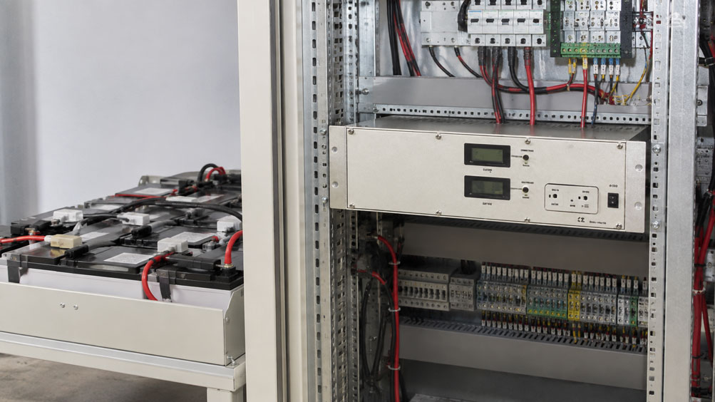
A 24 V control system needs to continue operating for another hour in the event of a mains failure.
There is sufficient space for a battery in the control cabinet, and a battery backup charger is intended to simultaneously:
- supply the loads,
- charge the battery,
- keep the battery permanently ready for operation,
- take over the power supply in the event of a mains failure,
- prevent deep discharge.
At first glance, the selection seems simple:
24 V system → 24 V charger → 24 V battery
In practice, however, this assignment is not sufficient.
At least the following factors are decisive:
- battery chemistry,
- permissible charging voltage,
- charging characteristic,
- maximum charging current,
- continuous current of the connected loads,
- required backup time,
- ambient temperature,
- aging reserve,
- deep-discharge protection,
- monitoring and alarm signaling.
A particularly common sizing error is to consider only the current drawn by the loads.
During normal mains operation, a battery backup charger often has to provide simultaneously:
load current + battery charging current
.
In simplified form:
Idevice ≥ Iload,max + Icharging
provided that the specific system does not use a different current distribution or charging priority strategy.
Equally important:
The designation “24 V” describes the nominal voltage of the system. The actual charging and float voltage required, however, depends on the battery type, state of charge and often also on the battery temperature.
An AGM, gel or lithium battery must therefore not be connected to just any 24 V charger based solely on its nominal voltage.
Chargers and battery backup chargers can be found at ICS Schneider under Chargers / Battery Backup Chargers. Further devices in the power supply range can be found under Power Supply.
Table of Contents
- What distinguishes a battery backup charger from a conventional charger
- Why 24 V does not automatically mean the correct charging voltage
- Define the battery type first
- Distinguish between lead-acid, AGM and gel batteries
- Use lithium batteries only with suitable charging electronics
- Select the correct charging characteristic
- Understanding the IUoU charging characteristic
- Correctly assess float charging
- Consider temperature compensation
- Place the temperature sensor on the battery rather than the charger
- Size charging and load current together
- Consider recharge time after a mains failure
- Determine battery capacity from the backup time
- Allow for aging and temperature as capacity reserves
- Consider parallel load and peak currents
- Set deep-discharge protection correctly
- Use battery monitoring and alarm contacts
- Check behavior during mains failure
- Consider cable cross-section and voltage drop
- Protect the battery circuit correctly
- Typical faults in 24 V battery backup systems
- Systematic selection procedure
- Practical example: 24 V control system with external battery
- Suitable ICS products
- Conclusion
- FAQ
What distinguishes a battery backup charger from a conventional charger
A conventional charger primarily has the task of charging a battery.
A battery backup charger, on the other hand, is typically used in a system in which the battery and loads form part of a common power supply concept.
During normal operation, in simplified form:
Mains → battery backup charger → loads
and simultaneously:
Battery backup charger → charge / maintain battery
If the mains supply fails, the battery takes over the power supply:
Battery → loads
Typical applications
- alarm systems,
- monitoring systems,
- control systems,
- telecommunications,
- switchgear,
- mobile systems,
- measurement and data acquisition systems,
- safety-related auxiliary power supplies.
A DC UPS consists of several functions
Depending on the design, these may include:
- power supply unit or charger,
- battery,
- charge management,
- deep-discharge protection,
- battery monitoring,
- alarm contacts,
- changeover or decoupling elements.
Before making a selection, it must therefore be checked which of these functions are already included in the battery backup charger and which are required separately.
Why 24 V does not automatically mean the correct charging voltage
The term:
24 V system
initially describes the nominal voltage of the power supply.
However, a battery is not necessarily charged at exactly:
24.0 V
.
Distinguish between nominal voltage and charging voltage
For a battery, the following must be distinguished, among other things:
- nominal voltage,
- charging voltage,
- float charging voltage,
- end-of-discharge voltage.
These values are not identical.
The load must also tolerate the actual system voltage
If the battery and loads are connected directly to the same DC bus, the operating voltage during charging may be higher than the nominal 24 V.
It must therefore be checked that:
permissible input voltage range of load ≥ actual voltage range occurring in the battery backup system
This applies, for example, to:
- PLC systems,
- relays,
- transmitters,
- communication devices,
- alarm devices.
Define the battery type first
The charger should not be selected before the battery has been selected or clearly defined.
The correct sequence is:
Application → battery type → battery parameters → charging method → charger
Why this is important
Different battery types require different:
- charging voltages,
- charging currents,
- charging phases,
- temperature compensation,
- cut-off conditions.
A charging method that is suitable for one battery type may be unsuitable for another.
Distinguish between lead-acid, AGM and gel batteries
AGM and gel batteries fundamentally belong to the lead-acid battery family.
However, their construction differs and they may require different charging parameters.
Flooded lead-acid battery
Conventional flooded lead-acid batteries contain liquid electrolyte.
During charging, the following factors must be considered, among others:
- gassing threshold,
- temperature,
- water loss,
- ventilation,
- permissible charging current.
AGM
In AGM batteries, the electrolyte is absorbed in a glass-fiber mat.
AGM batteries are frequently used in low-maintenance or sealed battery backup applications.
However, they require the charging parameters specified by the battery manufacturer.
Gel
In gel batteries, the electrolyte is immobilized in gel form.
Here too, the charging voltage must not simply be adopted from any other lead-acid battery.
The battery data sheet is decisive
At least the following should be known for selection:
- nominal voltage,
- nominal capacity in Ah,
- permissible charging current,
- charging voltage or charging method,
- float charging voltage,
- temperature range,
- temperature coefficient, where applicable,
- permissible end-of-discharge voltage.
Terms such as AGM or gel therefore do not replace the specific manufacturer’s data for the battery being used.
Use lithium batteries only with suitable charging electronics
A lithium battery must not be connected to an existing battery backup charger simply because its nominal voltage is approximately compatible with the 24 V system.
Lithium is not a single battery technology
The term lithium covers different cell chemistries.
Their:
- cell voltage,
- maximum charging voltage,
- permissible temperature,
- protective functions
may differ.
Consider the BMS
Many lithium battery systems have a:
BMS = Battery Management System
The BMS monitors, for example:
- cell voltages,
- temperature,
- charging and discharging current,
- undervoltage,
- overvoltage.
Charger and BMS must be compatible
It must be clarified:
- which charging characteristic is required,
- whether continuous float charging is permissible,
- which charging current is approved,
- how the BMS disconnects in the event of faults,
- whether the battery backup charger is compatible with this behavior.
A charging method intended for lead-acid batteries should therefore not be used for a lithium battery without explicit approval.
Select the correct charging characteristic
A charger does not simply limit the voltage.
Depending on its design, it operates with a defined combination of current and voltage regulation.
I characteristic
With current regulation:
I = charging current
is the primary controlled parameter.
U characteristic
With voltage regulation, the output voltage is limited to a defined value.
IU characteristic
A common combination is:
I → U
Charging initially takes place with limited current.
Once the battery reaches the specified voltage, voltage regulation takes over.
Multi-stage charging methods
With multi-stage charging methods, the voltage can additionally be reduced to a lower float value after the main charging phase.
The required characteristic must be derived from the battery requirements.
Understanding the IUoU charging characteristic
The designation IUoU is used for a multi-stage charging characteristic.
In simplified form, it consists of:
I phase → U charging phase → U float phase
Phase 1: Current-limited charging
When the battery is more deeply discharged, the charging current is limited to a defined maximum value.
Phase 2: Voltage-limited charging
Once the battery reaches the specified charging voltage, this voltage is maintained.
The current typically decreases as the state of charge increases.
Phase 3: Float charging
After sufficient charging, the voltage can be reduced to a float value intended for continuous operation.
Do not assume a charging characteristic
The designation:
24 V battery backup charger
alone does not prove that a particular IUoU method or battery charging characteristic is available.
The specific charging characteristic must be compared with the battery requirements using the technical documentation of the charger.
Correctly assess float charging
In a battery backup system, the battery may remain fully charged and connected to the system for long periods.
This operating condition has different requirements from occasionally charging a mobile battery.
Purpose of float charging
The battery should:
- maintain its state of charge,
- compensate for self-discharge,
- be subjected to as little electrochemical stress as possible.
Voltage too high
A continuously excessive charging voltage can accelerate aging, particularly in lead-acid batteries.
Voltage too low
A continuously insufficient voltage can result in the battery not remaining fully charged.
Less usable capacity will then be available during a later mains failure.
Battery backup operation is a continuous operating condition
Correct float charging is therefore important not only for the state of charge, but also for the achievable battery service life.
Consider temperature compensation
The optimum charging voltage of a battery can depend on temperature.
This is particularly relevant for lead-acid batteries.
Basic principle
As battery temperature rises, many lead-acid batteries require a lower charging voltage.
At lower battery temperatures, a higher charging voltage may be required within the permissible operating limits.
The exact temperature coefficient is battery-specific
The adjustment should not simply be taken from a generic table value.
The battery manufacturer’s specifications are decisive.
Why this is particularly important in a control cabinet
The battery temperature can differ significantly from the ambient temperature outside the control cabinet.
Heat sources may include:
- power supply units,
- power electronics,
- relays,
- transformers,
- other components generating power losses.
As a result, a system may operate for extended periods in summer at battery temperatures significantly higher than assumed during the original design.
Place the temperature sensor on the battery rather than the charger
If a charger supports true temperature-compensated battery charging, the relevant temperature should reflect the battery temperature as accurately as possible.
Internal device temperature is not the same thing
A charger may have internal temperature monitoring, for example to protect its own electronics.
This does not automatically mean:
battery temperature is measured → charging voltage is adjusted accordingly
Check particularly carefully with an external battery
If the battery is located, for example:
- in the lower section of the control cabinet,
- in a separate battery cabinet,
- several meters away from the charger,
its temperature may differ significantly from the electronic temperature of the charger.
Important selection question
If temperature compensation is required, the specific question should be:
Does the charger have an external battery temperature sensor, and is the charging voltage adjusted according to this temperature?
Size charging and load current together
A common mistake is to select a 6 A charger for a system with a continuous load of 6 A.
In normal operation, there may then be virtually no current left available to recharge a discharged battery.
Simplified sizing
If the loads and battery are supplied simultaneously:
Idevice ≥ Iload,max + Icharging
Example
Maximum continuous current of the 24 V loads:
7 A
Required available battery charging current:
3 A
This gives, in simplified form:
Idevice ≥ 7 A + 3 A = 10 A
A device with, for example, a 12 A output current would provide a corresponding current reserve under these simplified conditions.
Consider device-specific current distribution
Some systems have:
- charging current limitation,
- load prioritization,
- dynamic current distribution.
In such cases, sizing must be based on the specific device concept.
Consider recharge time after a mains failure
The required backup time is only one aspect of the design.
Once the mains supply returns, the battery must also be recharged sufficiently quickly.
Simplified estimate
If a capacity of:
ΔC
has been removed from a battery, a very simplified theoretical lower limit is:
tcharging ≈ ΔC / Icharging
The actual charging time is longer
The actual charging process is not an ideal constant-current charge all the way to 100%.
With many charging methods, the current decreases toward the end of charging.
Charging losses also occur.
Why this matters
If a second mains failure occurs shortly after the first, the full battery capacity may not yet have been restored.
For critical systems, the question should therefore not only be:
How long can the battery supply the system?
but also:
How quickly is the required operational readiness restored after a discharge?
Determine battery capacity from the backup time
For an initial approximate calculation:
Cideal = Iload · t
where:
C= capacity in Ah,I= load current in A,t= time in h.
Example
A 24 V system requires a constant:
4 A
and is intended to provide backup for:
1.5 h
.
Purely mathematically:
Cideal = 4 A · 1.5 h = 6 Ah
However, 6 Ah would only be the theoretical ideal value
In practice, the following must additionally be taken into account:
- permissible depth of discharge,
- battery aging,
- temperature,
- discharge rate,
- voltage limit of the load,
- deep-discharge threshold,
- required safety reserve.
The actual nominal capacity required is therefore normally higher than the purely calculated minimum capacity.
Allow for aging and temperature as capacity reserves
A new battery does not retain the same usable capacity throughout its entire service life.
Aging
As operating time increases:
- capacity may decrease,
- internal resistance may increase,
- voltage may drop more sharply under load.
Low temperature
At low temperatures, the available battery capacity may decrease.
High temperature
Although high ambient temperatures may temporarily change certain electrical characteristics, they accelerate aging in many battery systems.
Design for end of service life
A safety-related system should therefore not be calculated solely using the nominal capacity of a brand-new battery.
The reserve should be selected according to:
- battery type,
- maintenance interval,
- temperature range,
- required backup time
.
Consider parallel load and peak currents
The average operating current alone is often not sufficient.
Certain loads may briefly draw significantly more current.
Examples include:
- contactors,
- valves,
- motor drives,
- sirens,
- radio modules,
- heaters.
Example
Base load:
4 A
Additional short-term load:
5 A
This can temporarily require:
9 A
.
The battery must also be able to supply peak currents
During a mains failure, the battery or battery circuit must also be able to provide these peak currents.
The following should therefore be checked:
- battery discharge current,
- fuse,
- cable cross-section,
- contact current rating,
- voltage drop.
Set deep-discharge protection correctly
If a battery is discharged too deeply, it can be damaged.
Deep-discharge protection therefore disconnects the load before a critical undervoltage is reached.
The cut-off point has two functions
It protects:
- the battery against damaging deep discharge,
- the loads against undefined operation at excessively low voltage.
Cut-off threshold too low
The battery may be discharged unnecessarily deeply.
Cut-off threshold too high
The supply may be disconnected earlier than necessary and some of the usable battery capacity remains unused.
Assess the threshold according to the battery
The permissible end-of-discharge voltage depends on:
- battery type,
- discharge current,
- temperature,
- manufacturer approval
.
Use battery monitoring and alarm contacts
A battery backup charger should not attract attention only after the system has already shut down.
Useful conditions for monitoring may include
- mains available,
- mains failure,
- battery operation,
- low battery voltage,
- charging fault,
- device fault.
Potential-free contacts
Potential-free alarm signals can, for example, be forwarded to:
- PLC,
- building management system,
- alarm system,
- remote monitoring
.
Check the exact signal assignment
The specification:
potential-free alarm signals available
does not automatically mean that every desired status is available individually.
The exact signal assignment must be taken from the documentation for the specific device.
Check behavior during mains failure
For the application, it is not sufficient merely to have a battery.
The decisive question is:
What happens electrically at the moment the mains supply fails?
For example, check whether
- there is a transfer interruption?
- how large is the voltage step?
- does the PLC remain active without restarting?
- are communication devices reset?
- do relays remain reliably energized?
Perform a practical test
A battery backup system should therefore not be assessed only mathematically after commissioning.
A controlled mains failure test shows whether:
- the battery takes over,
- the voltage remains stable,
- alarms are triggered,
- the load actually continues operating.
Consider cable cross-section and voltage drop
An external battery may be connected to the battery backup charger using comparatively long cables.
The cable resistance then causes a voltage drop:
ΔU = I · R
During charging
The voltage drop can result in the voltage directly at the battery being lower than at the charger output.
During discharge
At high load current, additional voltage is dropped across the battery cable.
The load may therefore reach its undervoltage limit earlier.
Particularly critical at high currents
The following should therefore be included in the voltage-drop calculation:
- cable cross-section,
- cable length,
- terminal connections,
- fuses
.
Protect the battery circuit correctly
A battery can supply very high currents in the event of a short circuit.
The battery circuit must therefore be appropriately protected.
Position the fuse as close as possible to the energy source
A long unprotected cable between the battery and fuse can present a significant risk in the event of a short circuit.
Do not select the fuse based only on operating current
The following must be considered:
- maximum operating current,
- inrush and peak currents,
- cable cross-section,
- possible short-circuit current,
- breaking capacity,
- selectivity,
- manufacturer requirements.
Typical faults in 24 V battery backup systems
| Observation | Possible cause | Recommended check |
|---|---|---|
| Battery is significantly weakened after only a few years | Unsuitable continuous charging voltage or high temperature | Check charging characteristic, battery temperature and manufacturer specifications |
| Battery is not fully charged | Charging voltage or available charging current too low | Check voltage directly at the battery and current balance |
| Charger continuously operates at its current limit | Load current was sized without allowing for additional charging current | Measure load current and battery charging current separately |
| Recharge takes a very long time after an extended mains failure | Insufficient charging current reserve | Check available charging current while the load is operating simultaneously |
| Backup time is significantly shorter than calculated | Aging, temperature, discharge rate or battery too small | Check battery capacity and internal resistance |
| PLC restarts during mains failure | Supply interruption or excessive voltage drop | Measure the voltage profile during transfer |
| Battery becomes unusually warm in summer | High control cabinet temperature or unsuitable charging parameters | Check battery temperature and charging conditions |
| Temperature compensation appears ineffective | Only the internal device temperature is being monitored | Check whether a genuine external battery temperature sensor is present |
| System switches off very early during mains failure | Voltage drop or high deep-discharge threshold | Measure voltage simultaneously at the battery and load |
| Battery is deeply discharged | Deep-discharge protection missing or not operating appropriately | Test cut-off threshold and function |
| Alarm system does not report a mains failure | Alarm contact not connected or incorrect logic | Check signal assignment and alarm processing |
| New lithium battery does not operate with the existing backup system | Charging method or BMS not compatible | Check approval from battery and charger manufacturers |
Systematic selection procedure for a 24 V battery backup charger
- Record the loads: Document all 24 V loads and their continuous current.
- Determine peak current: Consider contactors, valves, radio devices or other short-term loads switching on.
- Check the permissible voltage range: Ensure that the loads tolerate the complete voltage range of the battery backup system.
- Define the backup time: For example 15 minutes, 1 hour or several hours.
- Define the battery type: Clearly specify lead-acid, AGM, gel or an approved lithium system.
- Check the battery data sheet: Record charging voltage, float charging, charging current, temperature coefficient and end-of-discharge voltage.
- Calculate the theoretical battery capacity: Use C = I · t as an initial starting point.
- Add reserve: Consider aging, temperature, discharge rate and safety requirements.
- Determine the required charging current: Consider the required recharge time.
- Size the battery backup charger: Take load current plus required battery charging current into account.
- Compare charging characteristics: Ensure that the device and battery are compatible.
- Check temperature compensation: If required, provide a genuine battery temperature sensor and appropriate control.
- Check deep-discharge protection: Coordinate the protective function and cut-off threshold with the battery.
- Define alarm signals: Integrate mains failure, battery operation and fault into the system concept.
- Size the battery cable: Consider current, cable length and voltage drop.
- Protect the battery circuit: Provide an appropriate fuse according to the electrical design.
- Check installation conditions: Consider ambient temperature, cooling and available control cabinet space.
- Test mains failure: Check battery takeover under realistic load.
- Test backup time: Do not only calculate it theoretically, but verify it in practice as part of the intended maintenance concept.
Practical example: 24 V control system with external battery
An industrial control system must continue operating during a mains failure.
During normal operation, the system requires:
6 A at 24 V
During certain switching operations, it briefly requires:
8 A
.
The required backup time is:
60 minutes
Step 1: theoretical battery capacity
For the continuous load, the idealized calculation gives:
Cideal = 6 A · 1 h = 6 Ah
Step 2: do not use 6 Ah as the final battery size
The 6 Ah is only the mathematical ideal value.
For the actual design, the following must additionally be considered:
- battery aging,
- temperature,
- permissible depth of discharge,
- voltage drop,
- load peaks,
- safety reserve.
The final nominal capacity is therefore determined using the battery data and required operating reserve.
Step 3: define the charging current
After a discharge, the battery should not simply be recharged eventually, but should return to operational readiness within a defined period.
Assume a charging current of:
4 A
should be available for the battery.
Step 4: output current of the battery backup charger
The control system continues to operate during recharging.
With a continuous load of 6 A, this gives:
Irequired ≈ 6 A + 4 A = 10 A
Short-term peaks and the specific current management of the charger must additionally be considered.
Step 5: check the 12 A device class
For this range, a battery backup charger with:
24 V / 12 A
may, for example, be technically suitable.
ICS lists the:
5326.1 battery backup charger in a 19″ system
with:
24 V / 12 A and external battery
.
Step 6: do not derive battery compatibility from 24 V / 12 A
Before selection, it must nevertheless be checked:
- which battery type is used,
- which charging characteristic is required,
- which battery size is permissible,
- which charging current is actually available,
- whether the required temperature compensation is supported.
Step 7: interpret the temperature function correctly
For the 5326.1, ICS specifies:
internal temperature monitoring
This specification should not be equated with:
external battery temperature sensor + temperature-compensated charging voltage
.
If temperature compensation is required for the battery being used, the specific function must be checked separately using the technical documentation or by requesting confirmation.
Step 8: protection and signaling functions
ICS also specifies the following for the 5326.1:
- overvoltage protection,
- deep-discharge protection,
- potential-free alarm signals.
This means that important functions for an industrial battery backup supply are fundamentally available.
The device documentation must be checked to determine which specific signals are output via the potential-free contacts for the planned application.
Result
The selection is therefore not based on:
24 V available → select 24 V charger
but on:
Load profile → backup time → battery type → required capacity → charging method → charging current → temperature conditions → protective functions → battery backup charger.
Suitable ICS products for 24 V battery charging and backup operation
5326.1 – Battery backup charger in a 19″ system
For an industrial 24 V battery backup system, the 5326.1 battery backup charger in a 19″ system listed by ICS is particularly relevant.
ICS specifies the following basic data:
| Feature | 5326.1 |
|---|---|
| Application | Battery backup charger |
| Nominal voltage | 24 V DC |
| Output current | 12 A |
| Battery | external battery |
| Input | 230 V AC, 50–60 Hz |
| Input/output isolation | galvanically isolated, floating |
| Protective functions | overvoltage protection, deep-discharge protection |
| Temperature | internal temperature monitoring |
| Signaling | potential-free alarm signals |
| Cooling | convection |
| Housing | 19″ BGT, 84 TE, 3 HE |
| Degree of protection / class | IP30 / I |
Why the 5326.1 is well suited to this topic
The device combines important functions for a battery backup application:
- 24 V supply,
- 12 A output,
- external battery,
- deep-discharge protection,
- alarm signals.
Further information can be found under 5326.1 Battery Backup Charger in a 19″ System at ICS Schneider.
Important note on temperature compensation
For the 5326.1, ICS specifies:
internal temperature monitoring
However, based on this specification it should not automatically be assumed that the device compensates the charging voltage based on an externally measured battery temperature.
If genuine battery temperature compensation is required, this function must be confirmed separately for the specific device/battery combination.
2263.0 – Automatic charger 12 V and 24 V
For applications that primarily require an automatic battery charger, ICS also offers the:
2263.0 Automatic Charger 12 V and 24 V.
For 24 V operation, ICS specifies:
24 V / 12 A
According to ICS, the device includes, among other things:
- automatic adaptation to the battery voltage,
- automatic charging current regulation,
- switching between maximum and half charging current,
- automatic transition to constant voltage,
- reverse-polarity protection.
It is therefore an automatic charger and not the same device concept as the 5326.1 battery backup charger.
Further information can be found under 2263.0 Automatic Charger at ICS Schneider.
2270.0 – Automatic charger 12 V and 24 V
A smaller version listed by ICS is the:
2270.0 Automatic Charger 12 V and 24 V.
For 24 V, ICS specifies:
24 V / 6 A
Here too, the specifications include:
- automatic adaptation to battery voltage,
- automatic charging current regulation,
- maximum or half charging current,
- automatic transition to constant voltage,
- reverse-polarity protection
.
Further information can be found under 2270.0 Automatic Charger at ICS Schneider.
Which ICS device is suitable for which application?
| Application | Suitable ICS solution |
|---|---|
| 24 V system with external battery and backup function | 5326.1 – 24 V / 12 A, external battery |
| Automatic charging of a 24 V battery with up to 12 A | 2263.0 |
| Automatic charging of a 24 V battery with up to 6 A | 2270.0 |
| Application with deep-discharge protection and potential-free alarm signals | 5326.1 |
| Permanent industrial backup of a 24 V supply | 5326.1, after checking battery and charging parameters |
Always size the battery together with the charger
Even with a technically suitable battery backup charger, the battery data must be known for the final selection.
In particular:
- battery type,
- capacity,
- permissible charging current,
- specified charging voltage,
- float charging voltage,
- temperature range,
- temperature compensation, where applicable.
An overview of the currently available devices can be found under Chargers / Battery Backup Chargers at ICS Schneider.
Conclusion
When selecting a battery backup charger for a 24 V system, nominal voltage alone is not sufficient.
The complete system consisting of:
mains supply + battery backup charger + battery + loads + protection and monitoring functions
is decisive.
The battery type should be defined first.
Lead-acid, AGM, gel and lithium systems may require different:
- charging characteristics,
- charging voltages,
- charging currents,
- temperature requirements
.
The terms:
24 V
and:
24 V battery
are therefore not sufficient for selecting a charger.
Particularly with lead-acid batteries, it should be checked whether the temperature dependency of the charging voltage specified by the battery manufacturer is taken into account.
The decisive point is:
Internal temperature monitoring of a charger is not automatically the same as temperature-compensated battery charging.
For current sizing, an important initial consideration is:
Idevice ≥ Iload,max + Icharging
The battery capacity can initially be estimated from:
C = I · t
.
The theoretical value must then be supplemented by real-world influences such as:
- aging,
- temperature,
- permissible depth of discharge,
- load profile,
- voltage limits,
- safety reserve
.
It should also be checked how quickly the battery can be recharged after a mains failure.
A sufficiently large battery is of little benefit if the charger has virtually no charging current available while the system is simultaneously operating under a high load.
Deep-discharge protection, battery-circuit protection and alarm signals must also be included in the overall assessment.
For an industrial 24 V battery backup application, the 5326.1 battery backup charger in a 19″ system with 24 V / 12 A and external battery listed by ICS provides a suitable device basis. However, the specific battery compatibility and any required temperature compensation must be checked using the battery being used and the technical device documentation.
For practical applications:
Record load current → determine peak current → define backup time → select battery type → check battery data sheet → calculate capacity → allow for aging and temperature reserve → determine required charging current → add load and charging current → check charging characteristic → clarify temperature compensation → assess deep-discharge protection → integrate alarm signals → size cable cross-section and fuse → practically test mains failure → regularly verify backup time.
FAQ: Correctly Selecting 24 V Battery Backup Chargers and Batteries
What is a battery backup charger?
A battery backup charger supplies the connected loads while simultaneously keeping a battery charged. In the event of a mains failure, the battery can take over the power supply if the system is designed accordingly.
What is the difference between a charger and a battery backup charger?
A conventional charger is mainly used to charge a battery. A battery backup charger, on the other hand, is part of a permanent power supply in which the battery and loads are operated together.
Is a battery backup charger the same as a DC UPS?
The terms overlap in practice, but are not necessarily technically identical. A complete DC UPS may include additional functions such as battery monitoring, defined changeover, communication interfaces or further protective functions.
Can I connect any 24 V battery to a 24 V battery backup charger?
No. Nominal voltage alone is not sufficient. Charging characteristic, charging voltage, charging current, battery chemistry and, where applicable, temperature compensation must be compatible.
Why is a 24 V battery not simply charged at exactly 24 V?
The nominal voltage of a battery is not identical to its required charging or float voltage. The correct values are determined by the battery type and manufacturer specifications.
Which batteries are commonly used for 24 V battery backup systems?
Depending on the application, lead-acid, AGM, gel or suitable lithium systems may be used.
Are AGM and gel batteries lead-acid batteries?
Yes. Both fundamentally belong to the lead-acid battery family, but have different internal designs and may require different charging parameters.
Can I charge an AGM battery using the same settings as a gel battery?
Not as a general rule. The required charging parameters should always be taken from the data sheet for the specific battery model.
Can I operate a lithium battery with a lead-acid battery backup charger?
Only if the battery or BMS and charger are explicitly compatible. A similar nominal voltage alone is not sufficient.
What does BMS mean?
BMS stands for Battery Management System. In corresponding battery systems, it monitors parameters including cell voltages, temperature and charging and discharging conditions.
What is an IU charging characteristic?
With an IU characteristic, the charging current is initially limited. Once the specified voltage is reached, a constant-voltage phase takes over.
What is an IUoU charging characteristic?
IUoU describes, in simplified form, a multi-stage process consisting of current-limited charging, a voltage phase and subsequent float charging.
Does every battery require an IUoU charging characteristic?
No. The suitable charging method depends on the specific battery type and manufacturer specifications.
What is float charging?
During float charging, an already charged battery is maintained at a defined state of charge over an extended period while compensating for self-discharge.
Why is an excessively high float charging voltage problematic?
It can subject the battery to continuous electrochemical stress and accelerate aging, particularly in lead-acid batteries.
Why is an excessively low float voltage problematic?
Over the long term, the battery may not remain fully charged and may provide less usable capacity during a mains failure.
What does temperature compensation mean in a battery charger?
It means that the charging voltage is adjusted according to the battery temperature, provided this is specified for the battery being used.
Why is temperature compensation important for lead-acid batteries?
The suitable charging voltage can depend on battery temperature. An incorrect charging voltage can negatively affect battery service life or state of charge.
Can the temperature inside the control cabinet be relevant?
Yes. The battery temperature can be significantly higher than normal room temperature due to power losses from other components.
Is internal temperature monitoring the same as temperature compensation?
No. Internal temperature monitoring may, for example, protect the charger electronics. For battery temperature compensation, the actual battery temperature must influence charging voltage regulation.
Where should a battery temperature sensor be installed?
If the battery manufacturer or charger specifies an external temperature sensor, it should be installed according to the relevant mounting instructions so that it measures the relevant battery temperature as reliably as possible.
How high must the output current of a battery backup charger be?
When supplying the loads and charging the battery simultaneously, both the load current and required charging current must generally be considered. The specific sizing depends on the charger’s current-management strategy.
What is a simple formula for current sizing?
As a simplified approach: Idevice ≥ Iload,max + Icharging.
How do I calculate the battery size for a required backup time?
As an initial approximate calculation, C = I · t can be used. This value must then be supplemented by real-world influences and an appropriate reserve.
How many Ah do I need for a 4 A load for one hour?
The mathematical ideal value is 4 Ah. The actually required nominal capacity must be larger when aging, temperature, depth of discharge, voltage drop and reserve are taken into account.
Why does the backup time decrease as the battery ages?
Because the usable capacity can decrease and the internal resistance can increase as the battery ages.
Why must peak current be considered?
Contactors, valves, motors or other loads can briefly require significantly more current than their normal continuous load.
What is deep-discharge protection?
Deep-discharge protection disconnects the load before the battery reaches a voltage that is too low for the intended operation and could damage the battery.
Why must the deep-discharge threshold not be set arbitrarily low?
Excessively deep discharge can damage the battery. In addition, connected loads may already be operating outside their permissible voltage range at very low voltages.
Why must the battery cable cross-section also be considered?
Because battery cables can cause a significant voltage drop at high currents. This affects both charging and the available voltage during a mains failure.
Does the battery need separate protection?
The battery circuit must be designed and protected according to the specific system, cables, battery and applicable protection requirements, because batteries can supply very high short-circuit currents.
Which alarm signals are useful in a battery backup system?
Typical conditions that can be monitored include mains failure, battery operation, undervoltage, charging fault or general fault. Which alarm signals are available depends on the specific device.
How do I test a 24 V battery backup system?
After commissioning, a controlled mains failure should be performed under realistic load. The voltage profile, battery takeover, alarm signaling and, where applicable, achievable backup time should be checked.
Why must recharge time be considered?
After a mains failure, the battery may be partially discharged. If the charging current is severely limited by the simultaneously operating system, it may take a very long time before full operational readiness is restored.
What is the ICS 5326.1?
The 5326.1 is a battery backup charger listed by ICS in a 19″ system for 24 V / 12 A and an external battery.
Which protective functions does the 5326.1 have?
ICS specifies, among other things, overvoltage protection, deep-discharge protection and internal temperature monitoring.
Does the 5326.1 have alarm signals?
Yes. The ICS product page specifies potential-free alarm signals. The exact assignment should be taken from the technical documentation.
Does the 5326.1 provide battery temperature compensation?
The ICS product page specifies internal temperature monitoring. This should not automatically be interpreted as external battery temperature measurement with temperature-dependent charging voltage. If this function is required, it must be confirmed separately for the specific version.
What is the ICS 2263.0?
The 2263.0 is an automatic charger for 12 V and 24 V. For 24 V, ICS specifies an output current of 12 A.
What is the ICS 2270.0?
The 2270.0 is also an automatic charger for 12 V and 24 V. For 24 V operation, ICS specifies 6 A.
Which ICS device is suitable for a 24 V battery backup system with an external battery?
The 5326.1 is explicitly listed on the ICS website as a battery backup charger with 24 V / 12 A and an external battery. Its suitability for the specific battery type and required charging characteristic must nevertheless be checked.
Where can I find chargers and battery backup chargers at ICS Schneider?
An overview can be found under Chargers / Battery Backup Chargers at ICS Schneider.
Where can I find additional power supply products at ICS Schneider?
Further power supply products can be found under Power Supply at ICS Schneider.