


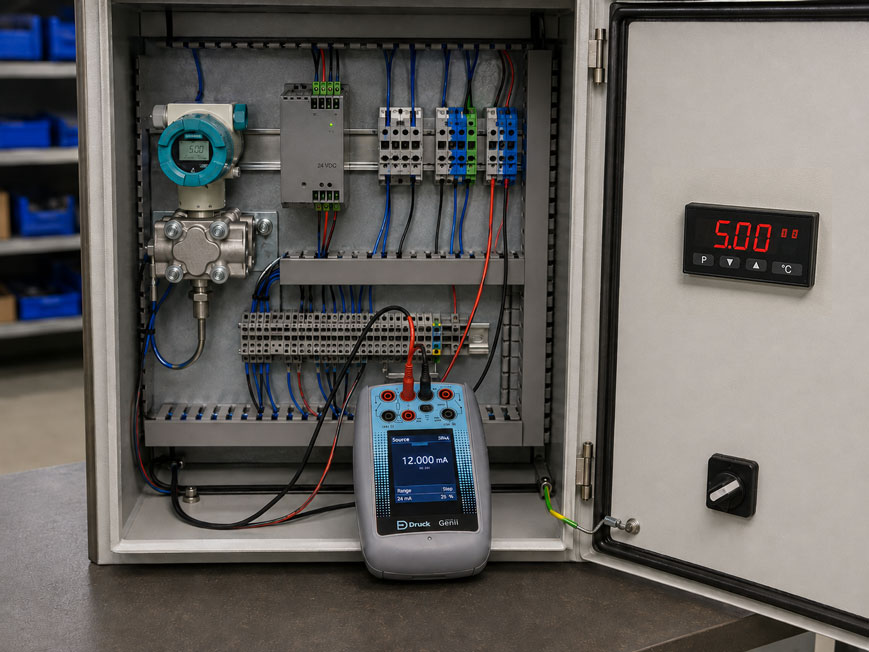
For example, a pressure transmitter has the measuring range:
0 … 10 bar
and provides an output signal of:
4 … 20 mA
However, the connected digital indicator should not display the current value, but directly:
0.00 … 10.00 bar
For this to work, the electrical input signal of the indicator must be scaled to the corresponding process range.
The following applies to the two endpoints:
4 mA = 0 bar
and:
20 mA = 10 bar
An input signal of 12 mA corresponds exactly to the midpoint of the current span and must therefore display:
5 bar
.
When configuring a 4–20 mA digital indicator, the input signal, lower and upper display value, decimal point and, where applicable, engineering unit must therefore be set correctly and independently of one another. It should also be defined how underrange, overrange and fault currents are displayed.
A suitable example from the ICS portfolio is the IM1 – 4-digit digital panel meter, 48 × 24 mm. It directly processes 0/4–20 mA and 0–10 V signals and has a freely configurable display range from -1999 to 9999. For applications requiring higher resolution, an analogue output or additional switching functions, the IM3 – 5-digit digital panel meter, 48 × 24 mm is available, for example.
Further devices can be found under Digital Indicators for DC Voltage and DC Current and under Measuring Instruments for Control Panel Construction at ICS Schneider.
Table of Contents
- What does 4–20 mA mean?
- Why does the signal start at 4 mA?
- How is a 4–20 mA signal scaled?
- Example: scaling 4–20 mA to 0–10 bar
- Scaling measuring ranges with a negative zero point
- Setting the decimal point correctly
- More decimal places do not mean higher accuracy
- Selecting the correct engineering unit
- Connecting a 4–20 mA indicator correctly
- Two-wire transmitters in the current loop
- Considering load and supply voltage
- Considering fault currents and NAMUR NE 43
- Do not confuse underrange with zero point
- Setting limits and alarm indication
- When additional linearisation points are useful
- Checking scaling with a current calibrator
- Practical example: 0–16 bar pressure transmitter
- Typical fault patterns
- Configuring a digital indicator systematically
- Suitable digital indicators from ICS Schneider
- Conclusion
- FAQ
What does 4–20 mA mean?
The current signal:
4 … 20 mA
is one of the most commonly used analogue standard signals in industrial measurement technology.
A transmitter converts a physical measured quantity proportionally into an electrical current.
Pressure example
| Pressure | Output current |
|---|---|
| 0 bar | 4 mA |
| 2.5 bar | 8 mA |
| 5 bar | 12 mA |
| 7.5 bar | 16 mA |
| 10 bar | 20 mA |
The digital indicator therefore initially receives only an electrical current.
It must know which process value corresponds to:
4 mA
and which process value corresponds to:
20 mA
.
Why does the signal start at 4 mA?
A key advantage of 4–20 mA compared with 0–20 mA is the so-called:
Live Zero
The physical lower end of the measuring range is not represented by 0 mA, but by:
4 mA
.
This makes it possible to distinguish between
Measured value = 0% → 4 mA
and, for example:
Current loop interrupted → approximately 0 mA
.
In a 0–20 mA system, a current of 0 mA could represent both a valid measured value and a possible indication of a broken wire.
In addition, a two-wire transmitter can be powered from the current loop
This means that a minimum current is still available to power the transmitter electronics even at the lower end of the measuring range.
4 mA therefore does not mean “no current”, but rather the valid lower endpoint of the measuring range.
How is a 4–20 mA signal scaled?
For a linear measured quantity, the corresponding process value can be calculated using the following relationship:
X = Xmin + ((I - 4 mA) / 16 mA) · (Xmax - Xmin)
Where:
X= process value to be displayed,Xmin= lower measuring range value,Xmax= upper measuring range value,I= measured current.
Why 16 mA?
The usable signal span is:
20 mA − 4 mA = 16 mA
These 16 mA correspond to:
100% of the measuring span
.
Example: scaling 4–20 mA to 0–10 bar
A pressure transmitter has:
Measuring range: 0 … 10 bar
and:
Output: 4 … 20 mA
The following values are configured in the digital indicator
Lower input = 4.000 mA
Lower display value = 0.00 bar
Upper input = 20.000 mA
Upper display value = 10.00 bar
Check at 12 mA
With:
I = 12 mA
the result is:
X = 0 + ((12 - 4) / 16) · 10
therefore:
X = 5.00 bar
Check at 8 mA
X = 0 + ((8 - 4) / 16) · 10
results in:
X = 2.50 bar
This makes it easy to verify the scaling using only a few test points.
Scaling measuring ranges with a negative zero point
The 4–20 mA signal is not limited to measuring ranges that begin at zero.
For example, a pressure transmitter may have:
−1 … +9 bar
.
In this case:
| Current | Pressure |
|---|---|
| 4 mA | −1 bar |
| 12 mA | +4 bar |
| 20 mA | +9 bar |
Important
The input value:
4 mA
is not automatically set to:
0
.
It must be scaled to the actual lower measuring range value:
−1 bar
.
Setting the decimal point correctly
After scaling, it must be decided how the process value should be displayed.
For a measuring range of:
0 … 10 bar
possible display formats include:
0 … 10 bar0.0 … 10.0 bar0.00 … 10.00 bar0.000 … 10.000 bar
The appropriate display depends on the application
For a simple operating pressure indication:
6.3 bar
may be entirely sufficient.
For a more precise process sensor, however:
6.27 bar
may be appropriate.
The decimal point affects interpretation
A value of:
625
may mean, depending on the configured decimal point:
- 625,
- 62.5,
- 6.25,
- 0.625.
An incorrectly positioned decimal point can therefore result in a completely incorrect process display even when the electrical scaling itself is correct.
More decimal places do not mean higher accuracy
A common misconception is:
more displayed digits = more accurate measurement
This is not necessarily the case.
The overall accuracy is determined, among other things, by:
- sensor accuracy,
- transmitter accuracy,
- accuracy of the 4–20 mA input,
- resolution of the A/D converter,
- temperature drift,
- signal interference.
Example
A pressure transmitter may have a measurement error of, for example:
±0.5% of span
for a measuring range of:
0 … 10 bar
This already corresponds to:
±0.05 bar
A display of:
6.2537 bar
would therefore suggest a level of accuracy that the measuring system does not actually provide.
The number of displayed decimal places should therefore correspond to the actual measurement quality of the complete measuring system.
Selecting the correct engineering unit
A digital indicator should not only display numbers, but also provide an understandable process value.
Typical units include, for example:
- bar,
- mbar,
- Pa,
- °C,
- %,
- l/min,
- m³/h,
- mm,
- kg.
Consistency is important
If a transmitter is configured for:
0 … 1000 mbar
but the digital indicator should display:
0.000 … 1.000 bar
this is technically possible without any problem.
The scaling must then be:
4 mA = 0.000 bar
and:
20 mA = 1.000 bar
.
However, the unit used must be clearly recognisable to the operator.
Connecting a 4–20 mA indicator correctly
A current signal fundamentally differs from a voltage signal.
A current receiver is integrated into the current path.
In simplified form
for a current loop with an externally powered two-wire transmitter:
+24 V → transmitter → 4–20 mA input → 0 V
The same loop current flows through all components connected in series.
Multiple current receivers
If multiple devices are explicitly suitable for this configuration, for example:
- digital indicator,
- PLC analogue input,
- recorder
can be connected in the same current loop.
However, the required voltage drops or loads then add together.
Do not confuse this with voltage inputs
A:
0–10 V input
is normally connected in parallel with the signal source.
A:
4–20 mA input
on the other hand, is part of the current path.
Incorrect wiring can lead to:
- incorrect measured values,
- overloading of the signal source,
- failure of the current loop.
Two-wire transmitters in the current loop
With a conventional two-wire transmitter, the power supply and measurement signal are transmitted over the same two conductors.
The transmitter varies its current consumption according to the process value between:
4 … 20 mA
Example
A typical loop consists of:
24 V power supply → pressure transmitter → digital indicator → 0 V
The digital indicator must have a current input intended for this purpose.
Alternative with integrated transmitter supply
Certain digital indicators can themselves provide a power supply for connected sensors or transmitters.
Depending on the version, the IM3, for example, can be configured with an integrated transmitter supply.
The exact connection method must always be checked against the device configuration and terminal assignment.
Considering load and supply voltage
A two-wire transmitter requires a minimum voltage for its electronics.
In addition, every device connected in series causes a voltage drop.
In simplified form, the following must apply:
Usupply ≥ Utransmitter,min + Uindicator + Uadditional receivers + Ucable
Example
With a 24 V supply:
- transmitter,
- digital indicator,
- PLC input,
- cable resistance
must all remain within the available voltage budget.
If the supply voltage is too low
the transmitter may no longer be able to reach the specified:
20 mA full-scale value
at higher currents.
The result may be, for example:
18.7 mA instead of 20 mA
even though the process value has already reached the upper end of the measuring range.
An apparently incorrect scaling can therefore actually be caused by excessive total loop load or insufficient loop supply voltage.
Considering fault currents and NAMUR NE 43
Modern transmitters can output defined current levels for fault detection in addition to the normal 4–20 mA measuring signal.
In devices operating in accordance with NAMUR NE 43, ranges outside the normal measurement signal are typically used for diagnostics.
The following are frequently distinguished, for example:
| Current | Typical interpretation with NE 43 evaluation enabled |
|---|---|
| below 3.8 mA | Underrange |
| above 20.5 mA | Overrange |
| 3.6 mA or below | Fault signal / depending on transmitter |
| 21.0 mA or above | Fault signal / depending on transmitter |
However, the specific fault-current configuration must always be checked for the transmitter being used.
Why this is important for the digital indicator
A current of:
3.6 mA
must not simply be extrapolated as a normal process value if the transmitter is configured accordingly.
With a 0–10 bar measuring range, purely mathematical scaling would otherwise result in a negative pressure value.
Depending on the application, it may be more appropriate to use:
- fault indication,
- flashing display,
- alarm contact,
- underrange indication.
Do not confuse underrange with zero point
The valid zero point of a 4–20 mA measuring range is:
4 mA
A current of:
0 mA
is therefore not a process zero point in a normal 4–20 mA current loop.
Example
Measuring range:
0 … 10 bar
The following then applies:
| Current | Meaning |
|---|---|
| 4 mA | 0 bar |
| 12 mA | 5 bar |
| 20 mA | 10 bar |
| 0 mA | not a valid normal measured value |
If a digital indicator simply displays:
0.00 bar
in the event of a broken wire, this can be dangerously misleading to the operator.
A clear fault indication is preferable for safety- or process-relevant measuring points.
Setting limits and alarm indication
Many digital indicators offer limit functions in addition to simply displaying the process value.
With the IM1, for example:
- upper limit violations,
- lower limit violations
can be indicated by a flashing display. :contentReference[oaicite:0]{index=0}
The IM3 additionally offers, among other features, two PhotoMOS switching outputs and a flexible alarm system. :contentReference[oaicite:1]{index=1}
Pressure monitoring example
Measuring range:
0 … 10 bar
An alarm should be triggered at:
8.0 bar
This limit should be configured directly in the engineering unit:
bar
if the device supports this.
This avoids the need for the operator to first convert:
8 bar → 16.8 mA
.
When additional linearisation points are useful
A conventional pressure, temperature or level transmitter with a linear 4–20 mA output normally requires only two scaling points:
4 mA → lower measuring range value
and:
20 mA → upper measuring range value
Non-linear relationships
For certain applications, however, this linear assignment is not sufficient.
Examples include:
- non-linear tank geometries,
- certain displacement or position measurements,
- customer-specific characteristic curves.
Additional linearisation points can then be used.
The IM1 supports up to ten configurable linearisation points, for example. :contentReference[oaicite:2]{index=2}
The IM3 provides up to 30 additional configurable linearisation points and is therefore suitable for more complex characteristic curves. :contentReference[oaicite:3]{index=3}
Important
Linearisation in the digital indicator should not be used to artificially compensate for a sensor that is actually faulty.
It must first be determined whether:
- sensor,
- transmitter,
- current loop
are operating correctly.
Checking scaling with a current calibrator
After configuration, the digital indicator should be tested independently of the actual sensor.
For this purpose, a suitable current calibrator is connected directly to the 4–20 mA input.
Useful test points
| Signal | Percentage | Expected display for 0–10 bar |
|---|---|---|
| 4 mA | 0% | 0.00 bar |
| 8 mA | 25% | 2.50 bar |
| 12 mA | 50% | 5.00 bar |
| 16 mA | 75% | 7.50 bar |
| 20 mA | 100% | 10.00 bar |
This allows two things to be tested separately
First:
Is the digital indicator configured correctly?
Second:
Does the transmitter subsequently provide the correct current?
Separating these two checks makes troubleshooting considerably easier.
Practical example: 0–16 bar pressure transmitter
A pressure transmitter has:
0 … 16 bar gauge
and:
4 … 20 mA
The digital indicator should display:
0.00 … 16.00 bar
.
1. Select the input
Configure the indicator as:
Input = 4–20 mA
2. Set the lower scaling point
4.000 mA → 0.00
3. Set the upper scaling point
20.000 mA → 16.00
4. Set the decimal point
XX.XX
5. Test at 50%
Current calibrator:
12.000 mA
Expected display:
8.00 bar
6. Test at 25%
8.000 mA → 4.00 bar
7. Test at 75%
16.000 mA → 12.00 bar
If all test points are correct, the linear scaling is correct.
If the actual transmitter subsequently indicates an incorrect value
the cause may no longer be the digital indicator, but rather, for example:
- transmitter configuration,
- process pressure,
- zero shift,
- supply voltage,
- current loop.
Typical fault patterns
| Observation | Possible cause | Recommended check |
|---|---|---|
| Display shows 4.00 at 4 mA | Current value displayed instead of process value | Check input scaling |
| 4 mA displays 0 bar, but 20 mA shows the wrong full-scale value | Upper scaling value incorrect | Reconfigure the upper value |
| Zero point correct, intermediate values incorrect | Incorrect linearisation or linearisation points | Check characteristic curve |
| 12 mA does not correspond to 50% of the measuring range | Scaling or transmitter range incorrect | Test transmitter and indicator separately |
| Display is too high by a factor of 10 | Decimal point incorrectly configured | Correct decimal point |
| Display shows 0 in the event of a broken wire | Fault current interpreted as measured value | Configure fault behaviour |
| Display does not reach the full-scale value | Transmitter does not reach 20 mA | Check loop voltage and load |
| Measured value fluctuates | Interference or unstable current loop | Check wiring, shielding and supply |
| Display permanently too low | Transmitter incorrectly scaled | Check transmitter LRV and URV |
| Digital indicator shows a negative value below 4 mA | Linear extrapolation active | Configure underrange and fault indication |
| Additional receiver causes an incorrect indication | Total loop load too high | Calculate voltage budget |
| Display appears highly precise, but the final digit fluctuates | Too many decimal places | Reduce display resolution appropriately |
Configuring a digital indicator systematically
- Define the measurement task: Which physical quantity is to be displayed?
- Check the transmitter range: Clearly identify the lower and upper measuring range values.
- Check the output signal: Do not confuse 4–20 mA, 0–20 mA or another standard signal.
- Select the input type: Configure the digital indicator for a 4–20 mA current input.
- Set the lower scaling point: Assign 4 mA to the actual lower measuring range value.
- Set the upper scaling point: Assign 20 mA to the actual upper measuring range value.
- Set the decimal point: Choose a format appropriate to the required display and actual measurement accuracy.
- Set the unit: For example bar, °C, %, l/min or m³/h.
- Check fault behaviour: Configure underrange, overrange and fault current appropriately.
- Configure limits: If alarm or switching functions are required.
- Check the current loop: Verify supply voltage and total load.
- Inject the 4 mA point: Check the lower measuring range value.
- Inject the 12 mA point: Check the 50% point.
- Inject the 20 mA point: Check the upper measuring range value.
- Check additional intermediate points: Particularly for critical applications.
- Simulate fault current: If the system uses corresponding diagnostics.
- Document the parameters: Record input, scaling, unit, decimal point and alarm limits.
Suitable digital indicators from ICS Schneider
IM1 – 4-digit digital indicator, 48 × 24 mm
The IM1 is particularly suitable for simple 4–20 mA indication applications.
Key features include:
- 4-digit digital display,
- 48 × 24 mm format,
- 10 mm digit height,
- display range -1999 to 9999,
- 0/4–20 mA input,
- current input measuring range -22 … 24 mA,
- additional 0–10 V input,
- galvanically isolated 24 VDC supply,
- front-panel operation,
- IP65 front protection,
- min./max. recording,
- up to 10 configurable linearisation points,
- tare function,
- visual limit monitoring.
This makes the device suitable, for example, for local indication of:
- pressure,
- temperature,
- level,
- flow,
- position
from a standardised 4–20 mA signal. :contentReference[oaicite:4]{index=4}
IM3 – 5-digit digital indicator, 48 × 24 mm
For applications requiring a wider range of functions, the IM3 is available.
The device offers, among other features:
- 5-digit display,
- display range -19999 to 99999,
- 0/4–20 mA input,
- 0–10 V input,
- up to 30 additional configurable linearisation points,
- two PhotoMOS switching outputs,
- optional 0/4–20 mA or 0–10 V analogue output,
- alternatively integrated transmitter supply,
- min./max. memory,
- alarm functions,
- mathematical functions,
- moving average filtering.
The IM3 is therefore particularly suitable when, in addition to local indication:
- limit monitoring,
- signal retransmission,
- linearisation,
- additional process functions
are required. :contentReference[oaicite:5]{index=5}
Further digital indicators
ICS Schneider offers a wide selection of digital indicators for DC current and DC voltage signals as well as dedicated current-loop indicators. :contentReference[oaicite:6]{index=6}
Conclusion
Scaling a 4–20 mA digital indicator is fundamentally straightforward when the electrical signal quantity and the process value are treated separately and consistently.
4 mA is the lower measuring range value
The so-called Live Zero makes it possible to distinguish a valid process zero from a complete loss of current.
20 mA is the upper measuring range value
Between these two points, a linear measured quantity is scaled proportionally.
The decimal point changes the display, not the measurement accuracy
Too many decimal places can suggest a level of accuracy that the sensor and transmitter do not actually provide.
Fault currents must be handled separately
Currents below or above the normal measuring range may contain diagnostic information in appropriately configured transmitters and should not automatically be displayed as process values.
The current loop itself must also operate correctly
Supply voltage, minimum transmitter voltage, input load and other receivers connected in series determine whether the full 4–20 mA range can actually be achieved.
The configuration should always be checked in practice
Using test points of 4, 8, 12, 16 and 20 mA makes it quick and easy to check the zero point, intermediate values and full-scale value.
For practical applications
Determine transmitter measuring range → check output signal → configure digital indicator for 4–20 mA → assign 4 mA to the lower measuring range value → assign 20 mA to the upper measuring range value → select an appropriate decimal point → define the engineering unit → configure underrange and overrange → consider fault currents → check supply and loop load → verify the 4 mA, 12 mA and 20 mA points with a calibrator → check additional intermediate points → document parameters.
FAQ: Scaling a 4–20 mA Digital Indicator Correctly
How do I scale a 4–20 mA indicator to 0–10 bar?
Set the lower scaling point to 4 mA = 0 bar and the upper scaling point to 20 mA = 10 bar.
What pressure corresponds to 12 mA for a 0–10 bar range?
12 mA corresponds to 50% of the 4–20 mA span and therefore to 5 bar.
What does 8 mA correspond to for a 0–10 bar range?
8 mA corresponds to 25% of the measuring span and therefore to 2.5 bar.
What does 16 mA correspond to for a 0–10 bar range?
16 mA corresponds to 75% of the measuring span and therefore to 7.5 bar.
Why does a 4–20 mA signal not start at 0 mA?
The 4 mA value forms the so-called Live Zero. This makes it possible to distinguish the lower measuring range value from a complete loss of current or a broken wire.
Does 4 mA always mean a process value of zero?
No. 4 mA corresponds to the lower measuring range value. For a measuring range of -1 … +9 bar, for example, 4 mA corresponds to -1 bar.
What does 0 mA mean in a 4–20 mA loop?
0 mA is normally not a valid process value within a 4–20 mA range and may, for example, indicate an interrupted current loop.
What is the scaling formula?
For a linear range: X = Xmin + ((I – 4 mA) / 16 mA) × (Xmax – Xmin).
Can I scale a 4–20 mA sensor to any engineering unit?
Yes. The display range can be shown, for example, in bar, °C, %, l/min, m³/h or another appropriate engineering unit.
Can I scale 4–20 mA to a negative measuring range?
Yes. For example, 4 mA = -50 °C and 20 mA = +150 °C can be configured.
What does the decimal point do?
It determines the position of the decimal separator in the displayed process value. It does not change the physical measuring span.
Do more decimal places mean higher accuracy?
No. The actual accuracy is determined by the complete measuring system consisting of sensor, transmitter and indicator.
Why does my digital indicator show 4.00 at 4 mA?
The input is probably still configured to display the direct current value and has not yet been scaled to the required process range.
Why does the display not show the correct full-scale value at 20 mA?
Possible causes include an incorrectly configured upper scaling value, an incorrectly configured transmitter range or a transmitter that cannot reach 20 mA because of the current-loop conditions.
Why does a 4–20 mA transmitter sometimes fail to reach 20 mA?
One possible cause is insufficient supply voltage or excessive total load in the current loop.
What does load mean in a 4–20 mA loop?
The load is the electrical resistance against which the transmitter must drive its loop current. This includes input resistance and cable resistance, among other things.
Can I connect multiple indicators to a 4–20 mA loop?
Suitable current receivers can generally be connected in series. However, the permissible total loop load and available voltage budget must be observed.
Is a 4–20 mA input connected in parallel?
No. A current receiver is connected in the current path. This differs, for example, from a high-impedance voltage input.
What does NAMUR NE 43 mean?
NAMUR NE 43 describes, among other things, the use of defined current ranges outside the normal 4–20 mA measuring signal for detecting underrange, overrange and fault conditions.
What does a current of 3.6 mA mean?
For transmitters configured accordingly in line with NAMUR NE 43, a value of 3.6 mA or below may be used as a fault signal. The specific transmitter configuration is decisive. :contentReference[oaicite:7]{index=7}
What does a current above 21 mA mean?
For appropriately configured transmitters, a current of 21 mA or above may indicate a fault condition. Here too, the device configuration is decisive. :contentReference[oaicite:8]{index=8}
What is the easiest way to check the scaling?
The best method is to use a suitable current calibrator and apply defined currents such as 4, 8, 12, 16 and 20 mA to the input.
Why should I check 12 mA?
12 mA corresponds exactly to 50% of the 4–20 mA span, making it particularly suitable for quickly checking linear scaling.
When do I need additional linearisation points?
Additional linearisation points are useful when the relationship between the input signal and the required display value is non-linear.
Which ICS digital indicator is suitable for a simple 4–20 mA display?
The IM1 in 48 × 24 mm format has a direct 0/4–20 mA input and a freely configurable display range.
What advantages does the IM3 offer compared with the IM1?
The IM3 offers, among other features, a 5-digit display, additional linearisation points, switching outputs and, depending on the version, an analogue output or transmitter supply.
Where can I find further digital indicators?
Further devices can be found under Digital Panel Meters for DC Current and DC Voltage at ICS Schneider.