


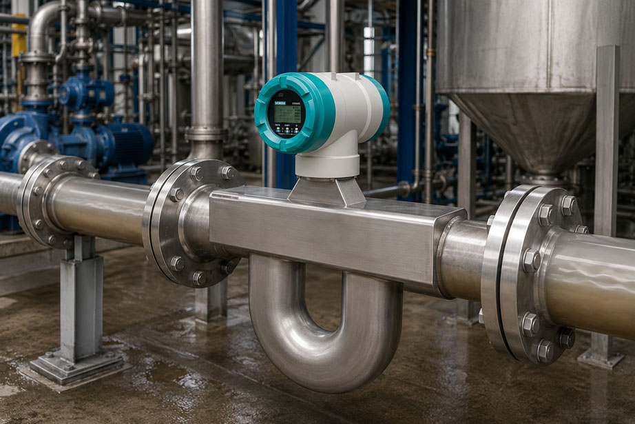
A Coriolis flowmeter has been measuring a solids-laden suspension for several years. The indicated mass flow still appears plausible, and there are no obvious disturbances during normal process operation. However, during regularly performed zero-point checks, it becomes apparent that the documented zero point is slowly changing from one maintenance interval to the next.
Does this already prove that the measuring tubes have been worn by abrasive particles? Not necessarily. Solids can indeed mechanically erode the inner wall of a Coriolis measuring tube and thereby change its wall thickness, stiffness and vibration behavior. At the same time, however, the zero point and other diagnostic parameters can also react to deposits, gas bubbles, pipe stresses, vibration, changing solids concentrations or different temperature conditions.
For this reason, a single process or diagnostic value is only of limited use as a wear indicator. Condition assessment becomes significantly more meaningful when several largely independent parameters are evaluated together over a longer period. These include the zero-point trend, density measurement under defined reference conditions, measuring tube stiffness or Tube Health, drive power and vibration behavior, as well as the complete operating and maintenance history.
The main advantage of such trend monitoring is that changes can be detected before the Coriolis flowmeter produces an obviously incorrect process value. This is particularly important in abrasive applications. A measuring tube can gradually change mechanically while mass flow and density still appear plausible during normal operation.
For a reliable assessment, however, a suitable initial condition must already be documented during commissioning. A later Tube Health value is considerably more useful if it is known how the same sensor behaved when new under the same installation conditions. The same applies to the zero point, density measured with a known reference medium and typical drive values.
The design of the measuring point also has a major influence on future wear. Particle hardness, size, shape and concentration are just as important as flow velocity, measuring tube material, mounting orientation and flow conditions immediately upstream of the sensor. A material with excellent chemical resistance is not automatically the best choice for abrasive loading.
In abrasive Coriolis applications, it is therefore advisable not to wait until a clearly incorrect flow value or mechanical measuring tube damage occurs. A more effective strategy is condition monitoring that establishes a baseline when the instrument is new and then systematically tracks the zero point, density, Tube Health and other diagnostic parameters over its operating life.
Why Is the Measuring Tube So Important in the Coriolis Principle?
In a Coriolis flowmeter, the measuring tube is not simply a hydraulic passage through which the medium flows. It is also a central part of the actual measuring system. Depending on the sensor design, one or more measuring tubes are set into controlled vibration.
When mass flows through these vibrating tubes, the Coriolis force causes characteristic changes in tube movement. Sensors detect the vibration or the phase shift between different sections of the measuring tube. The mass flow is determined from this behavior.
Density measurement is also closely linked to the mechanical condition of the measuring system. The resonant frequency of the filled measuring tubes changes depending on the mass of the medium and therefore allows the density to be determined.
This same principle also makes the system particularly sensitive to mechanical changes. If the measuring tube wall becomes thinner because of abrasion or corrosion, if material builds up on the inside or if the mechanical installation conditions change, a component of the actual measuring principle is altered.
| Change in the Measuring System | Possible Influence | Typical Diagnostic Approach |
|---|---|---|
| Abrasion / erosion | reduced wall thickness and altered stiffness | Tube Health, zero-point and density trends |
| Corrosion | material loss and possibly local weakening | material evaluation and condition diagnostics |
| Deposits | additional mass and altered vibration damping | drive level, density and cleaning verification |
| Mechanical pipe stress | changed vibration boundary conditions | check zero point and installation conditions |
| Gas bubbles | unstable vibration and density measurement | compare process conditions and diagnostic values |
In demanding applications, a Coriolis sensor should therefore not be assessed only by its current flow reading. The development of its mechanical condition is equally important.
How Does Abrasion Develop Inside the Measuring Tube?
Abrasion refers to the mechanical removal of material caused by solid particles in the flowing medium. Typical applications include mineral suspensions, slurries, drilling fluids, sand-water mixtures, lime or chalk suspensions, and liquids containing metal, mineral or crystalline particles.
During flow, these particles repeatedly strike the inner wall of the measuring tube. Depending on particle size, shape, hardness, concentration, flow velocity and impact angle, material can gradually be removed.
Wear does not necessarily occur uniformly over the entire tube length. Areas with flow deflection or locally increased particle concentration can be subjected to greater loading. In curved measuring tubes, local flow conditions can therefore have a major influence on the wear pattern.
The carrier liquid also plays a role. A viscous medium can transport particles differently from a low-viscosity liquid. This changes both particle velocity and impact behavior.
Which Particle Properties Influence Wear?
The general statement “the medium contains solids” is not sufficient for reliable instrument selection. Two suspensions with the same solids content can have completely different abrasive characteristics.
Fine, relatively soft particles in a viscous carrier liquid behave differently from sharp-edged quartz sand in water, for example. Particularly relevant parameters include solids content, average and maximum particle size, particle-size distribution, hardness, particle shape and density, as well as the viscosity of the liquid.
The stability of the suspension must also be considered. If heavy particles settle at low flow velocity, an uneven solids distribution can develop inside the sensor. This can result in both measurement errors and locally increased mechanical loading.
| Influencing Parameter | Tendency Under Abrasive Conditions | Practical Significance |
|---|---|---|
| Particle hardness | hard particles can cause greater material removal | do not select material based only on corrosion resistance |
| Particle shape | sharp-edged particles can be more aggressive | consider the actual particle geometry |
| Solids concentration | more particle contacts with the tube wall | evaluate cumulative loading over operating time |
| Flow velocity | higher relative velocity can increase abrasion | do not undersize the sensor unnecessarily |
| Viscosity | influences particle movement and sedimentation | include the carrier fluid in the design |
| Particle-size distribution | coarse and fine fractions behave differently | do not consider only the average particle size |
Why Flow Velocity Is Critical
With abrasive media, the highest possible flow velocity is not automatically advantageous. A certain minimum velocity may be necessary to keep a suspension homogeneous and prevent sedimentation. At the same time, however, increasing relative velocity between particles and the measuring tube wall can significantly increase mechanical material removal.
A Coriolis flowmeter should therefore not be selected unnecessarily small simply to operate at a high percentage of its nominal measuring range. A smaller nominal diameter results in a higher average flow velocity at the same volumetric flow and may therefore increase abrasive loading.
The optimum design is therefore a compromise between measurement performance, pressure loss, flow velocity, self-cleaning behavior, sedimentation risk and expected service life.
For highly abrasive applications, the permissible or recommended flow velocity should be coordinated with the instrument manufacturer based on the actual process and particle data.
Consider Inlet Flow Conditions and Pipe Bends
Coriolis flowmeters often do not require long conventional upstream and downstream straight runs for their basic measuring function. However, this does not mean that the flow conditions are completely irrelevant when abrasive media are involved.
If a 90° pipe bend, control valve, reducer or pump outlet is located immediately upstream of the sensor, strongly asymmetric or turbulent flow profiles can develop.
Abrasive particles may then strike certain areas of the measuring tubes at an unfavorable angle or with locally increased concentration. This can increase material removal in these areas even though the measuring principle itself continues to function correctly.
For particularly abrasive applications, calmer and more symmetrical inlet flow conditions can therefore be beneficial. The question is not only what the measuring principle requires, but also what type of flow guidance minimizes mechanical attack on the measuring tubes.
Choosing the Correct Mounting Orientation for Suspensions
For solids-laden liquids, the mounting orientation should be selected so that neither sedimentation nor gas accumulation is encouraged. Particularly with heavy solids, a sensor may otherwise remain partially filled with settled material during low or interrupted flow.
A vertical installation with upward flow can be advantageous for settling suspensions. It supports the transport of heavy particles and reduces the risk of solids remaining permanently in lower areas of the sensor.
The exact mounting orientation always depends on the sensor design and the manufacturer’s specifications. Curved measuring tubes may have different requirements from straight-tube geometries.
An unsuitable orientation can promote not only deposits but also trapped gas. Both can affect density measurement, zero-point stability and vibration behavior.
Selecting the Correct Measuring Tube Material
When selecting the measuring tube material, chemical corrosion and mechanical abrasion must be considered separately. A material can have excellent chemical resistance to a process medium and still exhibit unfavorable abrasive wear when exposed to hard particles.
Conversely, a mechanically robust material may be chemically unsuitable. The selection must therefore be based on the combination of process medium, temperature, solids type, particle hardness, concentration, flow velocity and process pressure.
For the SITRANS FCS600, for example, wetted versions are available in AISI 316L and Alloy 22. Alloy 22 provides high chemical corrosion resistance for many applications. However, this must not automatically be interpreted as meaning that it offers greater abrasion resistance in every suspension.
The more corrosion-resistant material is not automatically the more wear-resistant material. In abrasive applications, chemical and mechanical loading must always be evaluated together.
What Changes When the Measuring Tube Wall Becomes Thinner?
If the wall of a measuring tube becomes thinner because of abrasion or corrosion, not only its mechanical strength changes. The mechanical properties of the vibrating measuring system also change.
Possible effects include changes in tube stiffness, mass, natural frequency, resonance behavior, mechanical symmetry and response to the electromagnetic drive. Local material removal can additionally create mechanical asymmetry.
These changes can in turn affect mass flow measurement, density determination and the zero point. The important point, however, is that initial wear does not necessarily produce an obviously incorrect flow reading immediately.
This is exactly where condition diagnostics become valuable. Mechanical changes may become visible as a trend before the normal process indication becomes abnormal.
What Does the Zero-Point Trend Indicate?
The zero point of a Coriolis flowmeter describes the behavior of the sensor when the measuring system is completely filled and the actual flow is zero. Under reproducible conditions, this value should remain as stable as possible over a long period.
If the zero-point check is repeated regularly under comparable conditions, its development over time can become a useful diagnostic parameter.
| Time | Observation | Assessment |
|---|---|---|
| Commissioning | record reference value | baseline for future comparison |
| after 6 months | value almost unchanged | normal development |
| after 12 months | slight reproducible shift | continue monitoring the trend |
| after 18 months | further change in the same direction | compare additional diagnostic parameters |
| later, clearly outside initial condition | trend confirmed | investigate cause and evaluate maintenance action |
A continuous change can indicate that the mechanical or process-related conditions of the sensor have changed. The zero point is therefore useful for trend monitoring, but it is not specific enough on its own to justify the conclusion that the measuring tube is worn.
Why Zero-Point Drift Does Not Automatically Mean Wear
The zero point does not respond exclusively to the wall thickness of the measuring tubes. Mechanical pipe stresses, changed supports, vibration, gas bubbles, deposits, inhomogeneous suspensions and temperature conditions can also influence the value.
A zero-point check is particularly problematic if the process only appears to be stationary. If an isolation valve is not fully closed or a small residual flow remains, the measuring system may interpret this actual flow as an apparent zero error.
For a reproducible test, the sensor must be completely filled with medium and free from trapped gas bubbles. The flow must actually be zero, and the temperature and process condition should remain as stable as possible.
A changed zero point is therefore a diagnostic indication, but not proof by itself of measuring tube wear.
Can Density Measurement Indicate Measuring Tube Wear?
Density measurement in a Coriolis instrument is based on the resonance behavior of the filled measuring tube. If the mechanical structure of the tube changes, the calculated density can therefore also change in principle.
A long-term density trend can consequently be useful for condition monitoring. At the same time, density is also a genuine process variable. In a suspension, it changes if the solids concentration, composition, temperature or gas content changes.
A density deviation therefore becomes a useful instrument-condition indicator only when it is evaluated under known and reproducible reference conditions.
If, for example, the same reference medium is used repeatedly during maintenance at a comparable temperature and the instrument shows a systematic density shift over several years, this trend is considerably more relevant diagnostically than a density change during a variable production process.
Measuring Tube Stiffness as a Condition Parameter
For monitoring measuring tube wear, diagnostic functions that evaluate mechanical properties of the vibrating system as directly as possible are particularly useful. If the measuring tube wall becomes thinner, its stiffness changes.
Modern Coriolis systems can monitor such changes using Tube Health or Tube Integrity functions. These functions do not simply evaluate the current flow value. Instead, they compare the current mechanical condition of the sensor with a previously stored reference condition.
A long-term change can therefore indicate erosion, corrosion or other material loss. The information is particularly valuable when the reference condition was recorded during commissioning under the actual installation conditions.
This is important because not only the measuring tube itself but also the mechanical installation can influence the vibration behavior of the sensor.
Monitoring Drive Power and Vibration Condition
The measuring tubes of a Coriolis sensor must be maintained in controlled vibration. For this purpose, the measuring system uses an electromagnetic drive. The required drive power or drive level can provide additional information about the operating condition.
A significant increase in energy demand can, for example, be associated with gas bubbles, high viscosity, strongly damping media, solids deposits or changed mechanical conditions.
This parameter is therefore also not a unique wear indicator. However, when combined with Tube Health, zero point, reference density and sensor signals, it provides a much more complete picture.
Especially when several independent diagnostic parameters drift in the same direction over several maintenance cycles, the probability of an actual sensor change becomes significantly higher.
Distinguishing Abrasion from Deposits
Abrasive suspensions can cause two opposite types of changes in the measuring system. With abrasion, material is removed from the measuring tube wall. The wall thickness decreases and the mechanical stiffness may change.
With deposits, the opposite occurs: additional material accumulates on the inner wall. This increases the mass of the vibrating system, may reduce the free internal cross-section and can increase vibration damping.
Both effects can influence resonance behavior, density measurement, zero point and drive demand. A general diagnostic indication that the measuring system has changed must therefore not automatically be interpreted as direct proof that the measuring tube wall has become thinner.
Depending on the process, crystallization, product buildup or other deposits must also be ruled out. Cleaning followed by repeated diagnostics can help distinguish deposits from permanent material loss.
Why Baseline Values from the New Condition Are Important
Trend monitoring only works reliably if a defined initial condition is available. The diagnostic parameters relevant to future condition assessment should therefore ideally be documented during commissioning.
These include in particular the zero point, density of a known reference medium, available Tube Health or stiffness values, typical drive values and, where relevant, sensor signals. Temperature, installation conditions, typical flow and solids concentration should also be recorded.
These values form the baseline for the specific sensor. Later inspections can then be compared not only with general limits but with the actual initial condition of the same measuring point.
Especially with slowly progressing wear, the change relative to the baseline is often considerably more meaningful than one isolated absolute diagnostic value.
Trend Monitoring Instead of Individual Values
A single diagnostic value provides only limited information. A slightly changed Tube Health value may initially be caused by process or installation conditions. If the same deviation occurs during several inspections and continues to increase, however, a clear trend develops.
For predictive maintenance, not only the current value but especially the absolute change since commissioning, the change since the previous inspection and the rate of change are therefore important.
The trend should also be correlated with operating data. In abrasive applications, for example, the cumulative mass of solids that has passed through the sensor may be a much more meaningful loading parameter than calendar time alone.
A sensor that has operated for only a few hundred hours under low solids loading within twelve months has experienced a completely different mechanical load from an instrument that has operated continuously for several thousand hours.
Defining Maintenance Intervals Based on Risk
There is no universal maintenance interval for abrasive media. A suitable inspection strategy depends on particle hardness, particle size, solids content, flow velocity, operating hours, measuring tube material and process risk.
For a new application that is not yet sufficiently understood, relatively short diagnostic intervals may initially be appropriate. For example, a reference check could be performed at commissioning and then after three, six and twelve months.
If the zero point, Tube Health, reference density and other diagnostic parameters remain stable, the interval can subsequently be extended. If a reproducible trend appears early, however, the inspection interval should be shortened and the process conditions investigated at the same time.
Possible measures include reducing flow velocity, selecting a different sensor size, optimizing the mounting orientation or improving the inlet flow conditions upstream of the meter.
When Recalibration Is Useful
Internal condition diagnostics do not replace metrological calibration. The two methods answer different questions. Diagnostics investigate whether the condition of the sensor or its vibrating measuring system has changed. A traceable calibration determines the actual measurement deviation of the flowmeter relative to a reference.
Recalibration is particularly useful when a significant diagnostic trend is observed, the zero point has changed permanently or a reference comparison becomes abnormal. Prescribed calibration intervals may of course also apply independently of condition diagnostics.
With abrasive media, material removal can eventually change measurement performance. Conversely, severe deposits can also influence the balance and vibration behavior of the measuring system. Calibration then determines whether the mass flow measurement still remains within the required tolerance.
In simplified terms: diagnostics = monitor sensor condition and calibration = determine measurement deviation.
Practical Example: Abrasive Suspension in a Process Line
In a production plant, a mineral suspension is measured using a Coriolis flowmeter. The medium contains approximately 20% solids, and the sensor has been operating mainly continuously for two years.
During commissioning, the zero point, density with a defined reference medium, a tube-condition value and typical drive parameters were documented. These values serve as the baseline.
During the first maintenance inspections, the diagnostic values remain largely stable. After approximately 18 months, however, the zero point begins to show an increasing deviation from its initial value. During normal production, mass flow and density still appear plausible.
The first step is therefore to determine whether the changed zero point is reproducible. The sensor is completely filled, flow is stopped reliably and checks are made for trapped gas bubbles, unstable temperature and unusual pipe vibration. The zero-point deviation remains.
Additional diagnostic parameters are then compared with the baseline. The Tube Health value or tube-condition diagnostic also shows a progressive change. At the same time, the indicated density of a defined reference medium has shifted slightly.
Several independent indications are therefore developing in the same direction. During inspection of the installation, it is also found that a pipe bend is located immediately upstream of the flowmeter and that the flow velocity is relatively high. The solids may therefore be striking the sensor under unfavorable flow conditions.
During a planned shutdown, the sensor is removed and inspected. The examination confirms increased material loss. For the replacement installation, not only the sensor and measuring tube material are reconsidered, but also nominal size, flow velocity, mounting orientation and inlet conditions.
Regular tube-condition diagnostics are also permanently incorporated into the maintenance strategy.
The key advantage of condition monitoring in this example is that the change was detected before a complete sensor failure, a major measurement error or, in the worst case, leakage from the measuring tube occurred.
Planning and Inspection Checklist
- Record the complete chemical composition of the medium and possible corrosion exposure.
- Determine the type, concentration, hardness and shape of the solids.
- Consider average and maximum particle size as well as particle-size distribution.
- Evaluate the measuring tube material for both chemical and mechanical suitability.
- Do not undersize the sensor unnecessarily and verify the resulting flow velocity.
- Consider pressure loss, sedimentation risk and required minimum velocity together.
- Evaluate unfavorable flow deflections immediately upstream of the sensor in abrasive applications.
- For settling suspensions, select a suitable mounting orientation according to the manufacturer’s specifications.
- Avoid gas accumulation and undefined two-phase conditions wherever possible.
- Document the zero point under defined conditions during commissioning.
- Store the available Tube Health or tube-condition reference.
- If useful for the application, document the density of a known reference medium.
- Store typical drive values and other relevant diagnostic parameters as a baseline.
- Carry out repeat inspections under conditions that are as similar as possible.
- Evaluate diagnostic values as trends rather than only as current individual values.
- Correlate changes with operating hours and cumulative solids throughput.
- If abnormal trends occur, shorten inspection intervals and investigate process conditions.
- If necessary, perform a traceable flow calibration.
- Document limits, warning criteria and required actions for the specific application.
Common Mistakes
- Treating all solids-laden media as equally critical: Particle size, shape, hardness and concentration have a major influence on abrasion.
- Selecting the smallest possible Coriolis sensor: The resulting higher flow velocity can significantly increase wear.
- Selecting the material solely on corrosion resistance: Chemical resistance does not automatically mean high abrasion resistance.
- Ignoring a pipe bend immediately upstream of the sensor: Turbulent particles can strike the measuring tubes more aggressively in localized areas.
- Allowing sedimentation inside the measuring system: Deposits can influence density, zero point and vibration behavior.
- Immediately interpreting zero-point drift as measuring tube wear: Gas bubbles, vibration, pipe stress and deposits can also alter the zero point.
- Setting the zero point with residual flow present: The actual flow is incorrectly stored as a zero correction.
- Automatically interpreting density changes as sensor wear: In suspensions, a change in solids concentration alone can change the actual process density.
- Looking only at the current Tube Health value: The long-term change relative to the baseline is usually more meaningful.
- Failing to store reference values during commissioning: Later changes become considerably more difficult to evaluate.
- Treating Tube Health Check as equivalent to calibration: Condition diagnostics and determination of measurement deviation are different tasks.
- Confusing deposits with material removal: Both influence the vibrating system but require different corrective measures.
- Planning maintenance solely by calendar intervals: For abrasive media, operating hours or cumulative solids throughput may be more meaningful load indicators.
Suitable Coriolis Flowmeter
For demanding industrial Coriolis applications, the Siemens SITRANS FC640, for example, is a suitable option. The measuring system combines the SITRANS FCS600 sensor with the SITRANS FCT040 transmitter.
| Feature | Importance for Abrasive or Demanding Applications |
|---|---|
| SITRANS FCS600 sensor | Coriolis sensor for mass flow, density and temperature measurement |
| Measuring tube materials | versions available in AISI 316L and Alloy 22, among others |
| Nominal sizes | versions up to DN 65 |
| Process temperature | versions for high temperatures up to 350 °C |
| Process pressure | high-pressure versions up to 700 bar |
| SITRANS FCT040 | advanced transmitter with diagnostic and verification functions |
| Tube Health Check | comparison of the mechanical tube condition with a reference state |
| Additional measured variables | mass flow, density, temperature and volumetric flow |
For the condition monitoring described here, the SITRANS FCT040 is particularly relevant. The advanced transmitter supports a tube-condition check or Tube Health Check as well as additional diagnostic and verification functions.
During the tube-condition check, the mechanical stiffness of the measuring tube or vibrating system is evaluated, among other parameters. A reduction in wall thickness caused by erosion or corrosion can change this stiffness and therefore become diagnostically visible in comparison with the stored reference condition.
Such a function does not replace correct material selection or suitable hydraulic sizing of the measuring point. However, it provides an additional method for detecting changes at an early stage and planning maintenance more closely according to the actual condition of the sensor.
Further Coriolis systems can be found under Coriolis Flow Measurement at ICS Schneider.
Further electromagnetic, ultrasonic, vortex, Coriolis and mechanical flowmeters can be found under Flow Measurement Technology.
Conclusion
Coriolis flowmeters can provide accurate mass flow and density information even for solids-laden media. With abrasive particles, however, it must be considered that the measuring tubes themselves are part of the vibrating measuring system and may be subject to long-term mechanical wear.
The rate at which this wear progresses does not depend only on solids content. Particle hardness, particle size and shape, flow velocity, flow conditions, material and operating duration together determine the actual loading.
A zero-point shift can be a valuable first indication of a changed sensor condition. However, it is not specific to abrasion. Gas bubbles, deposits, mechanical pipe stresses, vibration and different test conditions can also influence the zero point.
The same applies to density measurement. A systematic density trend measured with a known reference medium can be diagnostically useful. A density change during normal production, on the other hand, may simply result from a different solids concentration or composition of the medium.
Condition assessment becomes more meaningful when mechanical diagnostic parameters such as Tube Health or tube stiffness are added. If the zero point changes at the same time, the reference density shifts and the mechanical condition value also develops a trend, the overall picture becomes considerably more reliable.
The foundation for this must be established during commissioning. Without a documented baseline, it is difficult to determine later whether a diagnostic value has actually changed or whether it has been typical for the specific installation from the beginning.
For abrasive applications, the most important strategy is therefore: Do not wait until measuring tube wear becomes visible as an incorrect flow reading. Document the zero point, reference density and available condition diagnostics while the sensor is new, and then systematically monitor their development in relation to operating hours and abrasive loading.
FAQ: Coriolis Flowmeters in Abrasive Applications
Can Coriolis flowmeters measure abrasive media?
In principle, Coriolis instruments can also measure solids-laden liquids and suspensions. Whether a particular sensor is suitable for long-term operation depends, among other things, on particle size, solids concentration, particle hardness, flow velocity, measuring tube geometry and material.
How does a Coriolis measuring tube wear?
Hard solid particles can remove material when they strike the inner wall. This abrasive or erosive wear can occur locally or over larger areas and can gradually reduce the measuring tube wall thickness.
Can measuring tube wear be detected from the zero point?
A long-term and reproducible change in the zero point can indicate a changed sensor condition. However, it is not conclusive because vibration, gas bubbles, deposits, pipe stress and unsuitable test conditions can also affect the zero point.
What is a Tube Health Check?
A tube-condition check compares mechanical properties of the vibrating measuring system with a reference condition. One of these properties can be measuring tube stiffness. If wall thickness changes because of erosion or corrosion, the stiffness can also change.
Does a Tube Health Check replace calibration?
No. Condition diagnostics investigate mechanical changes in the sensor. Calibration, by contrast, determines the actual measurement deviation relative to a traceable reference. The two methods serve different and complementary purposes.
Can abrasion also influence density measurement?
Yes. Density measurement is based on the resonance behavior of the measuring tube. Mechanical changes can therefore also influence the calculated density. For reliable condition assessment, however, density should be checked under known reference conditions.
Why can a suspension make the zero point unstable?
Heavy particles can settle at low flow velocity and create an uneven distribution inside the sensor. Gas bubbles or an inhomogeneous suspension can also influence vibration behavior.
Which mounting orientation is suitable for solids?
For settling suspensions, vertical installation with upward flow can be advantageous. This supports the transport of heavy particles. However, the installation instructions for the specific sensor always remain decisive.
Why can a pipe bend upstream of the Coriolis sensor be problematic with abrasive media?
A pipe bend can create asymmetric or turbulent flow. Solid particles may then strike certain areas of the measuring tubes at an unfavorable angle or with higher local concentration, increasing material removal.
Is Alloy 22 automatically better for abrasive media than stainless steel?
No. Alloy 22 is primarily used because of its chemical corrosion resistance. Abrasion resistance is a different material property. The selection must therefore consider both chemical and mechanical loading.
How often should a Coriolis flowmeter be inspected in abrasive applications?
There is no universally applicable interval. Shorter inspection intervals are advisable initially for a new application. Based on the observed trends, the intervals can later be adapted to operating hours, cumulative solids throughput and process risk.
Why should a reference measurement be stored immediately after commissioning?
Slowly progressing changes can only be assessed reliably when the initial condition has been documented. Baseline values for the zero point, density under reference conditions, Tube Health and other available diagnostic parameters are particularly useful.
Which is more meaningful: a single diagnostic value or the trend?
In most cases, the trend is considerably more meaningful. A one-time small deviation may result from process conditions. A reproducibly increasing change over several inspections provides much stronger information for condition monitoring and predictive maintenance.