


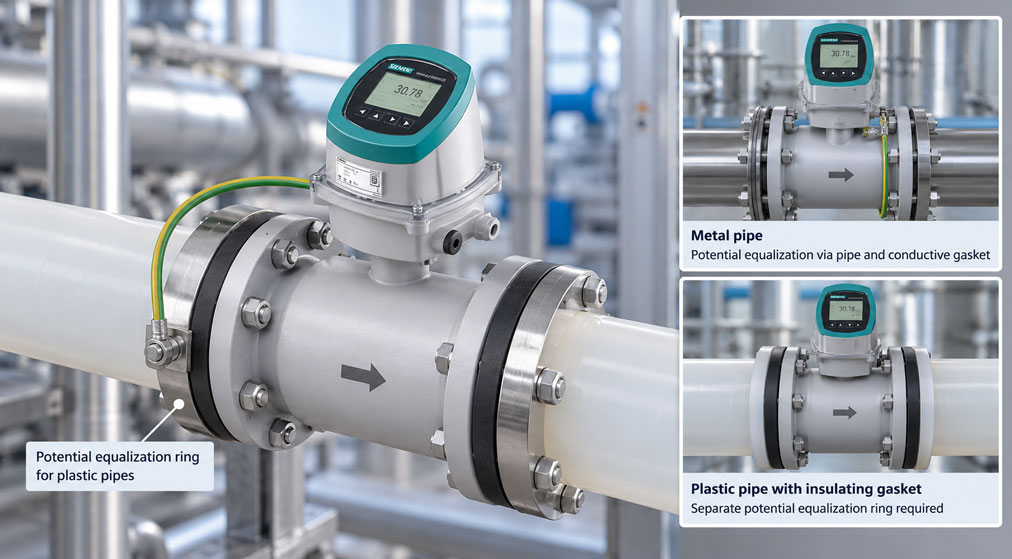
A SITRANS FMS100 is installed in a plastic pipeline. The flow is stable, the pipe is completely filled and the conductivity of the medium is well above the minimum requirement. Nevertheless, the indicated flow fluctuates more than expected and the zero point appears unstable. Could the cause actually be related to grounding?
Yes. An electromagnetic flowmeter requires a defined electrical reference potential between the sensor and the conductive medium. In a metallic pipeline, this potential can be established under suitable conditions via the pipe, flanges, gaskets and equipotential bonding.
In plastic pipes, however, this conductive path is not available. A similar situation occurs in a metallic pipeline whose internal lining electrically isolates the process medium completely from the pipe body.
With the SITRANS FMS100, it must therefore be checked what material the pipeline is made of, which gaskets are used and how electrical equipotential bonding to the medium is actually established.
The decisive factor is not whether a protective conductor exists somewhere outside the process. For electromagnetic flow measurement, the sensor and the conductive measuring medium must be at a defined common electrical potential.
Why does an electromagnetic flowmeter require equipotential bonding?
An electromagnetic flowmeter operates according to Faraday’s law of induction.
The sensor generates a magnetic field perpendicular to the direction of flow. When an electrically conductive liquid moves through this magnetic field, an electrical voltage is generated.
In simplified form:
U ∝ B × v × D
Where:
U= measuring voltage detected at the electrodes,B= magnetic flux density,v= flow velocity,D= effective pipe diameter.
The electrodes detect a very small electrical voltage directly from the medium.
To evaluate this voltage with minimal interference, the measuring electronics require a defined reference potential to the process medium.
For the SITRANS FMS100, Siemens explicitly states that the sensor must have the same electrical potential as the measured liquid in order to achieve optimum measurement results.
What does equal potential between sensor and medium mean?
Electrical potential describes, in simplified terms, the voltage level of a point relative to a reference.
For electromagnetic flow measurement, the following should not shift uncontrollably relative to one another:
sensor potential
and:
potential of the conductive medium
.
If the medium is not electrically connected clearly to the reference potential of the sensor, additional interference voltages can occur at the measuring electrodes.
The problem is not that no magnetic field is generated. Rather, the very small actual flow voltage can be superimposed by unwanted electrical potentials.
Possible consequences include:
- unstable zero point,
- fluctuating flow value,
- increased signal scatter,
- unstable measurement at low flow velocity,
- apparent flow values at standstill.
Why do plastic pipes require special attention?
Plastics such as:
- PVC,
- PE,
- PP,
- PVDF
are electrically non-conductive.
The pipe itself can therefore not provide electrical equipotential bonding between the process medium and the flow sensor.
A metallic flow sensor installed between two plastic pipe sections may have a conductive housing and metallic components, but this does not automatically mean that the medium is electrically at the same potential.
Especially when insulating gaskets are used, the conductive medium can be electrically isolated to a large extent from the external piping system.
In this case, the sensor requires a deliberate electrical contact to the medium.
A typical solution is a potential equalization or grounding ring.
Why can a metal pipe also behave electrically as a non-conductive pipe?
A pipeline can be made entirely of steel on the outside and still behave electrically like a plastic pipe from the point of view of electromagnetic flow measurement.
This can occur, for example, when the pipe is internally lined with an electrically insulating material.
Typical linings may consist of:
- plastic,
- rubber,
- PTFE,
- other corrosion-resistant coatings.
The metallic pipe body then has no direct electrical contact with the process medium.
For assessment, the decisive question is therefore not simply:
Is the pipe made of metal?
but:
Does the medium have a defined conductive connection to the equipotential bonding system?
If this contact is missing, the installation must be treated electrically as a non-conductive pipeline from the point of view of the measuring principle.
What role do graphite, EPDM and PTFE gaskets play?
For the SITRANS FMS100, Siemens explicitly takes the gasket material into account.
This is important because a gasket can either form part of the conductive potential path or interrupt it electrically.
For installation, Siemens essentially specifies the following combinations:
| Pipeline | Graphite gasket | EPDM or PTFE gasket |
|---|---|---|
| Electrically conductive pipeline | Equipotential bonding via electrically conductive graphite gasket | Equipotential bonding via the designated grounding strap |
| Electrically non-conductive pipeline | Equipotential bonding via electrically conductive graphite gasket | Separate potential equalization ring required |
This demonstrates why the pipe material alone must not be considered during planning.
An insulating gasket can interrupt an otherwise available conductive path.
When is a potential equalization ring required for the FMS100?
For electrically non-conductive pipelines, Siemens specifies a separate potential equalization ring when EPDM or PTFE gaskets are used.
The ring is positioned between the sensor or gasket and the pipe connection and is electrically in contact with the medium.
This gives the process medium a defined reference potential to the measuring system.
The function can be represented in simplified form as:
Medium → potential equalization ring → equipotential bonding → sensor
The ring is therefore not merely an arbitrary mechanical accessory.
Under these installation conditions, it is directly part of the electrical function of the measuring point.
Material, gasket, process compatibility, pressure rating and nominal diameter must match the specific FMS100 version.
Why are two rings specified for bidirectional measurement?
The SITRANS FMS100 can also be used for bidirectional flow measurements.
For a non-conductive pipeline with insulating gaskets, Siemens specifies the use of two grounding rings for bidirectional flow.
This provides a defined electrical connection to the medium on both sides of the sensor.
In simplified form:
Pipe → ring → FMS100 → ring → pipe
The installation should be carried out in accordance with the current Siemens operating instructions and the specific sensor version.
A second metallic ring should not simply be installed without considering material, installation position and electrical connection.
How is equipotential bonding implemented with conductive metal pipes?
With an electrically conductive pipeline, the pipe itself can generally form part of the equipotential bonding system.
Even here, however, it must be checked whether a suitable conductive path actually exists between medium, pipe and sensor.
According to Siemens, conductive graphite gaskets can provide equipotential bonding through the gasket itself.
If electrically insulating EPDM or PTFE gaskets are used instead, Siemens specifies equipotential bonding via the supplied grounding strap.
This electrically connects the conductive pipe sections or flanges to the sensor.
Important:
An installation that is metallic on the outside is not automatically electrically correct. Paint, coatings, insulating gaskets or non-conductive intermediate sections can interrupt the intended potential path.
Do not confuse equipotential bonding with protective grounding
The terms grounding, protective conductor and equipotential bonding are often used interchangeably in everyday practice.
For flow measurement, however, they serve different purposes.
| Function | Primary purpose |
|---|---|
| Protective conductor / PE | Electrical safety |
| Equipotential bonding of the measuring point | Defined reference potential between sensor and medium |
| Potential equalization ring | Electrical contact to the conductive process medium in an insulating pipe environment |
A protective conductor connected to the transmitter therefore does not automatically mean that equipotential bonding to the medium has also been implemented correctly.
Conversely, a potential equalization ring does not replace the required protective measures of the electrical installation.
Both requirements must be fulfilled in accordance with the manufacturer specifications and applicable electrical regulations.
Special case: DN 2 to DN 10
For certain small FMS100 versions, Siemens specifies an important special case.
For nominal sizes:
DN 2 ... DN 10
with Hastelloy or stainless-steel adapters, equipotential bonding can already be provided via these adapters.
This does not mean, however, that a general rule can be derived for all FMS100 versions.
During planning, the following must therefore always be taken into account for the actual ordered version:
- nominal size,
- process connection version,
- adapter version,
- gasket and
- pipeline type.
How does poor equipotential bonding affect the measurement?
Insufficient equipotential bonding does not necessarily result in a complete measurement failure.
This can make troubleshooting more difficult.
Possible symptoms include:
| Observation | Possible cause |
|---|---|
| Unstable zero point | Electrical reference potential not clearly defined |
| Measured value fluctuates despite constant process conditions | Potential or EMC influence |
| Error particularly visible at low flow | Useful signal small compared with interference signal |
| Indication reacts to nearby electrical equipment | Possible potential or EMC influence |
| Measurement becomes unstable after piping modification | Equipotential bonding interrupted during modification |
However, these symptoms do not automatically prove a grounding problem.
Similar effects can also be caused by:
- insufficient medium conductivity,
- partially empty measuring tube,
- air bubbles,
- electrode deposits,
- strongly pulsating flow,
- electrical interference.
Troubleshooting must therefore be carried out systematically.
Distinguishing equipotential bonding from minimum conductivity
For electromagnetic flow measurement, the medium must in principle have sufficient electrical conductivity.
For the SITRANS FMS100, Siemens specifies a minimum conductivity greater than:
5 µS/cm
This requirement must not be confused with equipotential bonding.
A medium may, for example, have a conductivity of:
500 µS/cm
and therefore be electrically very suitable for electromagnetic flow measurement.
However, if it is located in a plastic pipeline without the required equipotential bonding, the measuring point can still be electrically unfavourable.
Conversely, a perfectly installed grounding ring cannot make a medium with physically insufficient conductivity suitable for electromagnetic flow measurement.
These are therefore two separate requirements:
- The medium has sufficient electrical conductivity.
- The medium and sensor have a defined common reference potential.
What must be considered with remote installation?
The SITRANS FMS100 can be installed together with the SITRANS FMT020 in compact or remote configuration.
With remote installation, additional electrode and coil cables are used between sensor and transmitter.
Correct shielding and grounding of the signal connection therefore also become part of the measuring point.
For the sensor connection, Siemens specifies that grounding of the electrode cable is routed via the centre connection.
An additional black wire can be used for equipotential bonding in certain configurations, for example:
- with a 24 V DC supply without PE,
- with a sensor without grounding electrode.
This wire function should only be used in accordance with the specific wiring diagram of the device version being used.
An improvised additional ground can create unwanted parallel paths and is therefore not a substitute for correctly planned equipotential bonding.
Which diagnostic values help with troubleshooting?
The FMS100 is operated with a compatible transmitter. Together with the SITRANS FMT020, it forms the complete SITRANS FM120 flow measurement system.
The FMT020 can, among other things, measure or provide:
- volumetric flow,
- flow velocity,
- electrical conductivity,
- empty-pipe diagnostics,
- device self-test,
- additional diagnostic information.
If the measurement is abnormal, several variables should therefore be assessed together.
Example:
- conductivity stable and sufficient,
- pipe completely filled,
- process flow stable,
- measured value nevertheless highly unstable.
In this case, the electrical equipotential bonding of the installation should be checked specifically.
Conversely, if conductivity or empty-pipe diagnostics are also fluctuating significantly, the process side should first be investigated as well.
Practical example: FMS100 in a plastic pipeline
A SITRANS FMS100 is installed in a plastic pipeline in a process plant.
The medium is a conductive aqueous solution.
The pipeline is completely filled and the process operates at constant flow.
Initially, insulating EPDM gaskets are used for installation.
After commissioning, it becomes apparent that the indicated flow fluctuates more than expected, particularly at low flow velocity.
The following points are confirmed during inspection:
- medium conductivity sufficient,
- no visible air bubbles,
- pipe completely filled,
- sensor correctly sized,
- no defined electrical contact between medium and pipeline.
The installation is checked against the Siemens specifications.
Because:
- the pipeline is electrically non-conductive and
- EPDM gaskets are used,
the required potential equalization ring is integrated into the measuring point.
The medium then has a defined reference potential to the sensor.
The measurement is checked again for zero-point stability and reproducibility.
This example shows that even with sufficient medium conductivity, a non-conductive pipeline can require additional equipotential bonding.
Planning equipotential bonding systematically
- Determine the pipe material.
- Check whether the medium actually has electrical contact with the pipe.
- Take internal linings and coatings into account.
- Determine the gasket material.
- Check FMS100 nominal size and process connection.
- Apply the Siemens equipotential-bonding table for the specific combination.
- For non-conductive pipelines with EPDM/PTFE, provide the required potential equalization ring.
- For bidirectional measurement, take the requirement for two grounding rings into account.
- Check the special case DN 2 … DN 10 with suitable metal adapters.
- Consider protective grounding and metrological equipotential bonding separately.
- For remote installation, implement cable shielding and sensor grounding according to the wiring diagram.
- After commissioning, check the zero point at standstill.
- Evaluate conductivity and empty-pipe diagnostics as well.
- Check measurement stability under several flow conditions.
- Document the grounding or potential equalization ring arrangement.
Common mistakes
- Treating a plastic pipe like a metal pipe: The electrically conductive reference to the medium is missing.
- Considering only the material of the outer pipe wall: An insulating internal lining can electrically isolate the medium from the metal pipe.
- Ignoring gasket material: Graphite, EPDM and PTFE have different significance for equipotential bonding.
- Considering existing PE as sufficient equipotential bonding to the medium: Protective grounding and metrological equipotential bonding serve different purposes.
- Using any metal ring as a grounding ring: Material, process compatibility and sensor connection must match.
- Using only one ring in a bidirectional application: Siemens specifies two grounding rings for non-conductive pipelines with the corresponding insulating gasket in bidirectional flow applications.
- Assuming integrated grounding electrodes are always present: The actual sensor, adapter and connection version must be checked.
- Confusing a potential problem with low conductivity: Both causes are electrical, but physically different.
- Trying to “smooth out” the measured value with strong damping: Damping does not correct an incorrect electrical installation.
- Connecting shields and ground wires arbitrarily in remote installation: The Siemens connection specifications must be followed.
- Failing to recheck equipotential bonding after piping modifications: New gaskets or plastic intermediate sections can interrupt the original path.
SITRANS FMS100 and FMT020 as a flow measurement system
The Siemens SITRANS FMS100 is an electromagnetic flow sensor for electrically conductive liquids.
It is available in nominal sizes from:
DN 2 ... DN 100
and designed for flow velocities up to:
10 m/s
.
The standard measurement accuracy is:
±0.4 % of the flow reading
.
An optional high-accuracy calibration up to:
±0.2 % of the flow reading
is available.
Depending on the version, available options include:
- PFA or ceramic lining,
- Hastelloy C22 or platinum electrodes,
- various process connections,
- high-temperature versions up to 200 °C.
According to Siemens, the required minimum conductivity of the medium is greater than:
5 µS/cm
.
In combination with the SITRANS FMT020, the FMS100 forms the complete SITRANS FM120 electromagnetic flow measurement system.
The FMT020 provides, among other functions:
- flow and flow-velocity measurement,
- conductivity measurement,
- empty-pipe monitoring,
- device self-diagnostics,
- compact or remote installation.
Depending on the version, communication options such as HART, PROFINET, EtherNet/IP or Modbus RTU are available.
Further information can be found under SITRANS FMT020 transmitter, under electromagnetic flow measurement and under Siemens process instrumentation at ICS Schneider.
Conclusion
An electromagnetic flowmeter requires more than a sufficiently conductive medium. The sensor and process medium must also be at a defined common electrical potential.
With conductive metal pipes, this equipotential bonding can be established via suitable pipe connections, conductive gaskets or designated grounding straps.
With plastic pipes or electrically insulating lined pipelines, this natural conductive path is often missing.
For the SITRANS FMS100, the required solution therefore depends both on the electrical conductivity of the pipeline and on the gasket material.
For electrically non-conductive pipelines with EPDM or PTFE gaskets, Siemens specifies a separate potential equalization ring. For bidirectional measurements under these conditions, two grounding rings are specified.
Conductive graphite gaskets, on the other hand, can themselves form part of the equipotential bonding depending on the installation.
Protective grounding and metrological equipotential bonding must not be confused. A correctly connected PE does not indicate whether the medium actually has the same electrical reference potential as the sensor.
For stable FMS100 measurement, the following therefore applies: check pipe and liner material, take gasket material into account, establish the potential path specified by Siemens and, after commissioning, check the measuring point not only for flow but also for zero-point stability, conductivity and diagnostic status.
FAQ: SITRANS FMS100 in plastic and lined pipelines
Why does a SITRANS FMS100 require equipotential bonding?
The electromagnetic sensor measures a very small electrical voltage in the conductive medium. For low-interference measurement, sensor and medium must have a defined common electrical reference potential.
Does an FMS100 in a plastic pipeline require a grounding ring?
For electrically non-conductive pipelines with EPDM or PTFE gaskets, Siemens specifies a separate potential equalization ring.
Why is plastic problematic?
Plastic is electrically non-conductive and therefore cannot provide natural equipotential bonding between the process medium and the measuring system.
Does the same problem apply to lined metal pipes?
Yes. If an electrically insulating internal lining completely separates the medium from the metal pipe, the pipeline can behave electrically like a non-conductive pipeline from the point of view of the measuring principle.
What role does the gasket play?
A conductive graphite gasket can form part of the equipotential bonding. EPDM and PTFE gaskets are electrically insulating, so depending on the pipe type, a grounding strap or potential equalization ring is required.
Why are two grounding rings used for bidirectional flow?
For non-conductive pipelines with corresponding insulating gaskets, Siemens specifies two grounding rings for bidirectional flow so that the medium is connected to the equipotential bonding system in a defined manner on both sides of the sensor.
Is protective grounding the same as equipotential bonding of the measuring medium?
No. The protective conductor primarily serves electrical safety. Metrological equipotential bonding establishes a defined reference potential between the liquid and the sensor.
Does a metal pipeline always mean that no grounding ring is required?
No. Even with metal pipes, gaskets, coatings and the actual electrical contact must be considered. A metallic external construction does not guarantee a suitable potential path to the medium.
What applies to small FMS100 versions?
For DN 2 to DN 10 with certain Hastelloy or stainless-steel adapters, Siemens specifies equipotential bonding via the adapters. The specific device version must therefore be checked.
Can poor grounding cause a fluctuating flow value?
Yes. An undefined reference potential can cause interference voltages at the measuring electrodes and appear, for example, as an unstable zero point or fluctuating flow value.
Can stronger damping solve the problem?
Stronger damping can visually reduce fluctuations, but it does not correct faulty equipotential bonding. The electrical installation should first be implemented correctly.
Is sufficient conductivity the same as correct equipotential bonding?
No. The liquid must have sufficient electrical conductivity and must also have a defined electrical reference potential to the sensor. Both conditions must be checked separately.
What minimum conductivity does the SITRANS FMS100 require?
Siemens specifies a minimum medium conductivity greater than 5 µS/cm for the FMS100.
Which transmitter is used with the FMS100?
The SITRANS FMS100 can be combined with the SITRANS FMT020. Together, they form the SITRANS FM120 electromagnetic flow measurement system.