


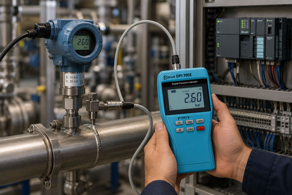
When a pressure transmitter shows incorrect values, the sensor itself is often suspected first. In practice, however, the cause is often found elsewhere in the measuring chain: wrong measuring range, wrong pressure type, shifted zero point, clogged process connection, unfavorable installation position, air in the measuring system, faulty wiring, incorrect 4–20 mA scaling or an incorrectly parameterized PLC.
A pressure transmitter does not measure in isolation. It is part of a measuring chain consisting of process connection, medium, pressure type, measuring cell, electronics, output signal, cable, power supply, analog input and display in the control system. If an error occurs at any point in this chain, the displayed pressure value may appear incorrect even though the actual sensor is technically in good condition.
This article shows how faults in pressure transmitters can be systematically narrowed down. The aim is not to replace the device immediately, but to check the cause step by step: process, installation, signal, scaling and reference measurement. This helps avoid unnecessary downtime, misdiagnoses and incorrect spare part orders.
Table of contents
- Basics: why pressure transmitters can show incorrect values
- Clarify the fault pattern first: offset, jumps, drift or completely wrong value?
- Check measuring range, pressure type and unit correctly
- Zero point, tare and overload: small shift with major impact
- Process connection, clogging and media influence
- Installation position, pressure line and hydrostatic effects
- 4–20 mA signal, wiring and PLC scaling
- Comparison measurement with a reference device: sensor or system?
- Practical example: pressure transmitter permanently shows 0.4 bar too much
- Which measuring instruments / products are suitable?
- Conclusion: do not replace the sensor before checking the measuring chain
- FAQ: frequently asked questions about incorrect pressure transmitter values
Basics: why pressure transmitters can show incorrect values
A pressure transmitter converts a process pressure into an electrical output signal. The 4–20 mA signal is particularly common, but depending on the device, voltage outputs, digital interfaces or fieldbus variants may also be used. The control system, PLC or data logger then converts this signal back into a pressure value.
For the displayed value to be correct, several things must match. The measuring range of the transmitter must suit the application. The pressure type must be correct, i.e. gauge pressure, absolute pressure or differential pressure. The process connection must transfer the actual pressure cleanly to the measuring cell. In addition, power supply, output signal, wiring and scaling in the control system must be correctly implemented.
An incorrect value therefore does not automatically mean that the measuring cell is defective. A transmitter may correctly output 12 mA while the PLC calculates an incorrect pressure value from it. Conversely, the PLC may be scaled correctly, but the process connection may be partially clogged. Or the zero point may have been adjusted while process pressure was present, shifting the entire measurement.
Systematic troubleshooting therefore always considers the entire measuring chain. Only once process, connection, installation, signal and scaling have been checked can it be reliably decided whether the pressure transmitter is actually defective or whether the cause lies outside the device.
| Fault pattern | Possible cause | First useful test step |
|---|---|---|
| Value is constantly too high or too low | Zero point shift, incorrect scaling, wrong pressure type | Check zero point, measuring range and PLC scaling. |
| Value jumps or is unstable | Process pulsation, air bubbles, EMC, loose terminal, unstable power supply | Measure the signal directly and examine process conditions. |
| Value responds very slowly | Clogged pressure connection, damping, long pressure line, viscous medium | Check process connection and pressure transmission. |
| PLC value does not match local display | Incorrect 4–20 mA scaling, wrong analog input, wiring fault | Measure mA signal and check scaling in the target system. |
| Value remains at minimum or maximum value | Cable break, overload, input outside range, faulty power supply | Check supply voltage, current signal and diagnostic messages. |
Clarify the fault pattern first: offset, jumps, drift or completely wrong value?
Before a pressure transmitter is removed, the fault pattern should be described as precisely as possible. A constant offset usually has different causes than a jumping value. Slow drift over several weeks indicates different problems than a suddenly completely incorrect measured value after maintenance or modification.
A constant offset is often caused by zero point shift, incorrect tare, installation position, hydrostatic pressure components or incorrect scaling. If a transmitter does not show zero when the system is depressurized, this is an important indication. However, it must be clear what “depressurized” means in the specific system. Gauge pressure, absolute pressure and differential pressure have different reference points.
Jumping or strongly fluctuating values can originate from the process itself. Pumps, compressors, fast valves, pressure surges or pulsating media create real pressure changes. In that case, the transmitter is not displaying incorrectly, but showing a dynamic process situation. However, there may also be an electrical cause, such as EMC coupling, a loose terminal, poor shielding or an unstable power supply.
If the fault occurs after a sensor replacement, PLC change, parameterization or maintenance, it should be checked very carefully what exactly was changed. In such cases, the cause is often not in the process, but in the measuring range, wiring, scaling or device version.
Check measuring range, pressure type and unit correctly
The measuring range is one of the first specifications that should be checked. A pressure transmitter with 0–10 bar provides a different scaling with a 4–20 mA output than a device with 0–16 bar or 0–25 bar. If the sensor has been replaced and the new measuring range does not match the old PLC parameterization, the controller will inevitably display incorrect values.
The pressure type is just as important. A gauge pressure transmitter measures relative to ambient pressure. An absolute pressure transmitter measures relative to vacuum. A differential pressure transmitter measures the difference between two pressure connections. If these pressure types are confused, measured values may appear incorrect even though the sensor is measuring exactly what it was designed for.
A typical example is confusing absolute pressure and gauge pressure. An absolute pressure sensor shows approximately 1 bar absolute at atmospheric pressure. A gauge pressure sensor shows 0 bar gauge under the same conditions. If the system expects a gauge pressure value but an absolute pressure transmitter has been installed, an apparent offset of about one bar occurs.
The unit must also be checked. bar, mbar, kPa, MPa, PSI and mmH₂O can easily be confused. Especially in international systems, replacement devices, data sheets or parameterizations in control systems, errors occur when a measuring range looks numerically correct but is stored in a different unit.
| Test point | Typical error | Practical effect |
|---|---|---|
| Measuring range | Sensor 0–16 bar, PLC still scaled to 0–10 bar | PLC systematically displays incorrect pressure values. |
| Pressure type | Absolute pressure used instead of gauge pressure | Value appears shifted by atmospheric pressure. |
| Unit | MPa, bar or PSI confused | Measured value is shifted by a factor or conversion error. |
| Output signal | 0–10 V expected, 4–20 mA supplied | Analog input processes the signal incorrectly or not at all. |
| Differential pressure connections | High and low side swapped | Sign or measuring direction is incorrect. |
Zero point, tare and overload: small shift with major impact
A shifted zero point is a common cause of incorrect pressure values. The error often appears unspectacular, but can have major consequences. If, for example, a transmitter shows 0.2 bar in a depressurized state, the entire measuring range is shifted by this amount. In control loops, level applications, filter monitoring or test benches, this can lead to incorrect decisions.
When adjusting the zero point, it must be clear which condition should actually be considered the zero point. With a gauge pressure transmitter, depressurized usually means open to atmosphere. With an absolute pressure transmitter, however, the zero point is vacuum, not ambient pressure. With a differential pressure transmitter, both sides must be correctly relieved or brought to the same reference pressure.
An accidentally activated tare function or digital zero point correction can also falsify a measurement. In some devices or displays, the zero point can be adjusted on site. This is practical if small installation effects need to be corrected. However, if this function is used incorrectly or not documented, implausible values may occur later.
Overloads or pressure peaks can also lead to permanent deviations. If a sensor has briefly been loaded significantly beyond its permissible range, the measuring cell may shift or become damaged. For recurring zero point problems, it should therefore be checked whether pressure shocks, valve impacts, pump starts or unsuitable measuring ranges are occurring.
Process connection, clogging and media influence
The process connection is the link between the process and the measuring cell. If this connection does not work properly, the transmitter can only record a distorted pressure. Especially with viscous, contaminated, crystallizing, sticky or particle-laden media, pressure channels may become partially or completely clogged.
Partial clogging is particularly deceptive. The transmitter does not necessarily show a constantly incorrect value, but reacts with delay, damping or only to larger pressure changes. In maintenance, this sometimes looks like a sluggish or defective sensor. In reality, however, the process pressure is no longer transmitted directly and quickly enough to the measuring cell.
Air or gas bubbles in liquid lines can also falsify measured values. In hydraulic or water-carrying systems, trapped air can lead to compressible behavior. Pressure builds up with delay, pressure peaks are transmitted differently and comparison measurements may deviate from one another.
With aggressive media, material compatibility must also be checked. Corrosion, deposits, damaged diaphragms or attacked seals can lead to drift, leakage or mechanical damage. In such cases, a flush process connection, suitable diaphragm seal, flushing connection or different installation method may be required.
Installation position, pressure line and hydrostatic effects
The installation position of a pressure transmitter can influence measured values. Especially with small measuring ranges, low pressures or sensitive differential pressure measurements, the position of the measuring cell may play a role. Some transmitters allow zero point adjustment after installation in order to compensate for position-related effects. However, this adjustment must be performed under the correct conditions.
In pressure lines, another effect is added: the liquid column. If a transmitter is installed below or above the actual measuring point, the hydrostatic pressure component of the line can shift the measured value. With water, a height difference of about one meter already corresponds to roughly 100 mbar. For very low measuring ranges, this is significant.
In differential pressure applications, such effects are even more critical. Different heights, impulse lines that are not completely filled, gas bubbles on one side or condensate in a line can distort the differential pressure. The transmitter then measures a real pressure difference, but not the process value that the operator actually expects.
The position in the process is also important. Directly downstream of pumps, valves, bends or throttling points, local pressure fluctuations, turbulence or pulsations can occur. A transmitter at an unfavorable location may then show a different value than a reference device at a calmer measuring point. For a good comparison measurement, the measuring points must therefore be selected carefully.
4–20 mA signal, wiring and PLC scaling
With many pressure transmitters, the measured value is transmitted via a 4–20 mA signal. This signal is robust and widely used in process automation. Nevertheless, many errors occur here because current loop, power supply, load resistance, analog input and scaling do not match correctly.
The basic logic is simple: 4 mA corresponds to the lower end of the measuring range, 20 mA to the upper end of the measuring range. For a measuring range of 0–10 bar, this means: 4 mA = 0 bar, 12 mA = 5 bar and 20 mA = 10 bar. However, if the PLC is scaled to 0–16 bar, it will display a different pressure value for the same current signal.
For this reason, the actual mA signal should always be measured when pressure values are incorrect. If the transmitter works plausibly locally or with reference pressure, but the PLC displays an incorrect value, the cause is often the scaling or analog input. Swapped channels, wrong signal type, missing loop supply or excessive load resistance can also cause problems.
The UPS4E loop calibrator is particularly helpful for this troubleshooting. It can be used to measure 4–20 mA signals, simulate defined mA values and power current loops. This makes it possible to check whether the PLC displays the correct pressure value at 4 mA, 12 mA and 20 mA – regardless of whether the pressure transmitter is currently working correctly or not.
| mA signal at 0–10 bar | Expected pressure value | Typical test |
|---|---|---|
| 4 mA | 0 bar | Check lower measuring range limit and zero point in the PLC. |
| 8 mA | 2.5 bar | Use intermediate value for plausibility check. |
| 12 mA | 5 bar | Use 50% point for quick scaling check. |
| 16 mA | 7.5 bar | Check linear behavior of display and PLC. |
| 20 mA | 10 bar | Check upper measuring range limit and limit value logic. |
Comparison measurement with a reference device: sensor or system?
A comparison measurement is often the fastest way to clarify whether the transmitter itself is measuring incorrectly or whether the fault lies in the process, installation or signal processing. For this purpose, a suitable reference device is connected as close as possible to the same pressure point. It is important that measuring range, accuracy, pressure type and medium suit the application.
A digital pressure gauge or test gauge can show on site which pressure is actually present. If the reference device and transmitter use the same pressure connection and still differ significantly, the cause is more likely to be the transmitter, zero point, measuring range or output signal. If both devices show the same value but the PLC displays something else, electrical signal processing is more likely.
In dynamic processes, comparison measurement must be interpreted carefully. A slow reference pressure gauge and a fast pressure transmitter may show different values under pulsating pressure, even though both are working correctly. Min/max functions, filter settings or measurement under stable process conditions can help here.
For a reliable statement, the measurement should ideally be performed at several pressure points, not just at one point. This helps determine whether it is a zero point error, span error, non-linearity or process problem. For quality-relevant applications, documented calibration of the measuring chain is useful.
Practical example: pressure transmitter permanently shows 0.4 bar too much
In a production plant, a pressure transmitter in the control system permanently shows about 0.4 bar more than expected. The process is running stably, and the operator initially suspects a defective sensor. The transmitter is to be replaced because the displayed value does not match experience from the plant.
Before replacement, a comparison measurement is carried out with a digital pressure gauge. The reference device is connected to a nearby test connection. This shows that the actual pressure is significantly closer to the transmitter value than to the expected value. The sensor is therefore not obviously defective. On closer inspection, however, it becomes apparent that the transmitter is installed below the actual measuring point and that the filled pressure line creates an additional hydrostatic pressure component.
The 4–20 mA signal is also measured. The loop current matches the pressure applied to the transmitter. The PLC scaling is also correct. The apparent error is therefore not caused by the electrical system, but by installation position and pressure line. After evaluating the hydrostatic correction, the measuring point is documented and the zero point is reassessed under defined conditions.
This example shows that an incorrect pressure value is not automatically a sensor fault. In this case, process connection, installation height and expected value were the decisive points. Without comparison measurement and mA testing, a functioning transmitter would have been replaced unnecessarily.
Which measuring instruments / products are suitable?
For selecting suitable pressure transmitters, ICS Schneider Messtechnik offers the category pressure sensors / differential pressure sensors. There you will find solutions for gauge pressure, absolute pressure and differential pressure as well as various measuring ranges, process connections, output signals and designs. In the case of recurring measurement problems, not only the measuring range should be evaluated, but also medium, connection type, pressure type, temperature, dynamics and installation situation.
Digital pressure gauges / test gauges are suitable for comparison measurements on site. They help to check the actual process pressure independently of the permanently installed transmitter. Depending on the application, accuracy, measuring range, pressure connection, resolution, min/max function and calibration certificate are decisive.
For service, maintenance and quick pressure diagnostics, the DPI705E precision pressure/temperature measuring instrument is also a suitable solution. Functions such as leak test, min/max hold, tare function, filter and alarm support troubleshooting when pressure values fluctuate, slowly drop or only become noticeable under certain operating conditions.
If a pressure transmitter provides a 4–20 mA output signal, the current loop should always be checked as well. The UPS4E loop calibrator is suitable for measuring and simulating mA signals and checking the scaling of PLC, data logger or control system. Especially when answering the question “sensor fault or PLC scaling?”, this test instrument is particularly helpful.
| Product / area | Typical use | Particularly relevant for |
|---|---|---|
| Pressure sensors / differential pressure sensors | Selection of suitable pressure transmitters and pressure sensors | Gauge pressure, absolute pressure, differential pressure, process connection and output signal |
| Digital pressure gauges / test gauges | Comparison measurement and reference pressure testing on site | Maintenance, service, plant testing, zero point check and plausibility check |
| DPI705E precision pressure/temperature measuring instrument | Pressure diagnostics, leak testing and mobile reference measurement | Pressure drop, pressure peaks, min/max values, tare function and stable on-site testing |
| UPS4E loop calibrator | Testing and simulation of 4–20 mA signals | PLC scaling, current loop, wiring, commissioning and troubleshooting |
Conclusion: do not replace the sensor before checking the measuring chain
If a pressure transmitter shows incorrect values, the sensor should not be replaced too quickly. The cause is often found in measuring range, pressure type, zero point, process connection, installation position, pressure line, medium, wiring or PLC scaling. As a result, a functioning transmitter may appear to be defective.
The most important recommendation is: first describe the fault pattern, then check process and installation, then measure the output signal and verify the scaling. A comparison measurement with a suitable digital pressure gauge or test instrument shows whether the error originates at the pressure point itself or only in the electrical processing.
Especially with 4–20 mA transmitters, the current loop is a central test point. If mA signal and reference pressure match, the fault is often in the display, PLC parameterization or scaling. Only once these points have been ruled out should replacement or calibration of the pressure transmitter be considered as the next step.
FAQ: frequently asked questions about incorrect pressure transmitter values
Why does my pressure transmitter show incorrect values?
Common causes include wrong measuring range, wrong pressure type, shifted zero point, clogged process connection, unfavorable installation position, air in the pressure line, incorrect wiring, unstable power supply, faulty 4–20 mA signal or incorrect PLC scaling.
Is the sensor always defective when pressure values are incorrect?
No. Very often the sensor is not defective. The error may be in the process connection, pressure line, zero point adjustment, parameterization or electrical signal processing. For this reason, the entire measuring chain should always be checked.
How do you check whether the measuring range is correct?
The measuring range on the nameplate, data sheet or parameterization is compared with the PLC scaling and the actual process pressure. If a sensor with a different measuring range has been installed, the scaling in the control system must be adjusted accordingly.
What happens if absolute pressure and gauge pressure are confused?
An absolute pressure sensor measures relative to vacuum, while a gauge pressure sensor measures relative to atmosphere. At atmospheric pressure, an absolute pressure sensor shows approximately 1 bar absolute, while a gauge pressure sensor shows 0 bar gauge. Confusing the two therefore leads to a significant offset.
Why does the transmitter not show zero when the system is depressurized?
Possible causes include zero point shift, wrong pressure reference, installation position, residual pressure in the system, hydrostatic pressure components or active tare. First, it should be clarified whether the sensor is truly depressurized and which pressure type is being used.
Can a clogged process connection cause incorrect values?
Yes. Deposits, crystallization, viscous media or dirt can narrow or block the pressure channel. The transmitter then reacts with delay, damping or displays an old pressure state. This is a common cause, especially with contaminated or viscous media.
Why does the pressure value fluctuate strongly?
Fluctuations can be caused by real process pulsations, pumps, valves, pressure surges or air bubbles. However, electrical causes such as EMC, loose terminals, unstable power supply or poor shielding may also be present. Direct measurement of the mA signal helps narrow down the cause.
How do you test a 4–20 mA signal from a pressure transmitter?
The loop current is measured with a suitable measuring instrument or loop calibrator. It is then checked whether the mA value matches the expected pressure. In addition, a defined mA value can be simulated in order to test PLC scaling independently of the transmitter.
Why does the PLC show a different value than the transmitter?
The cause is often the scaling of the analog input. If the measuring range of the transmitter does not match the PLC parameterization, the correct mA signal is converted into an incorrect pressure value. Swapped channels or wrong signal types are also possible.
What role does the installation position play?
The installation position can have an influence, especially with small measuring ranges and differential pressure measurements. In addition, height differences in filled pressure lines can generate hydrostatic pressure components. These must be considered when evaluating the measured value.
How does a liquid column affect the pressure value?
A liquid column generates hydrostatic pressure. With water, a height difference of approximately one meter corresponds to about 100 mbar. If the transmitter is mounted significantly above or below the measuring point, this component can shift the measured value.
When is a comparison measurement useful?
A comparison measurement is useful when it is unclear whether the transmitter or the system is the cause. A suitable reference device is connected as close as possible to the same pressure point. This makes it possible to check which pressure is actually present at the process connection.
Which reference device is suitable for testing a pressure transmitter?
Digital pressure gauges, test gauges or mobile pressure measuring instruments with a suitable measuring range, sufficient accuracy and appropriate process connection are suitable. For service and diagnostics, devices with min/max function, tare function or leak test are particularly helpful.
Can an incorrect unit be the cause?
Yes. If bar, mbar, kPa, MPa or PSI are confused, the value can deviate significantly. Especially in international projects, replacement devices and PLC parameterization, the unit should be checked carefully.
When should a pressure transmitter be calibrated?
Calibration is useful when reference measurements show deviations, quality requirements exist, the transmitter has been overloaded or measured values are no longer plausible. Depending on the application, not only the sensor but the entire measuring chain should be considered.
When should the pressure transmitter be replaced?
Replacement is useful if the transmitter is mechanically damaged, no longer measures stably, the measuring cell has been overloaded, the output signal or electronics are faulty, or calibration confirms unacceptable deviations. Before that, process, installation, signal and scaling should be checked.