


When testing electrical installations, the measuring instrument is not the only factor that determines a correct result. The existing network system is just as important. Whether TT system, TN-S system, TN-C-S system or IT system: protective measure, earthing, fault current path, RCD use and evaluation of measured values differ significantly. Anyone who does not take the network system into account may misinterpret measurement results or apply a test procedure that does not fit the installation.
In existing installations, industrial plants, medical areas, mobile installations, special networks or systems with their own power supply, it often happens that the network system is not clearly documented. The installation tester then displays measured values, but the evaluation remains uncertain. A loop impedance measurement, RCD test or earth resistance measurement has a different meaning in a TT system than in a TN system. In IT systems, special conditions apply because the first fault does not necessarily have to lead to immediate disconnection.
This article explains in practical terms why TT, TN and IT systems are tested differently, which measurements are particularly important and why an installation tester must always be used according to the network system, the protective measure and the specific installation. Work and testing on electrical installations may only be carried out by qualified personnel in compliance with the applicable standards, rules and manufacturer specifications.
Table of contents
- Basics: why the network system is decisive for testing
- Testing a TT system: earthing system and RCD at the center
- Testing TN-S and TN-C-S systems: loop impedance, protective conductor and short-circuit current
- Testing an IT system: insulation monitoring instead of classic disconnection logic
- Which measurements are particularly important for each network system
- Typical misinterpretations in existing installations
- Using installation testers correctly: measurement function is not the same as evaluation
- Practical example: loop measurement delivers apparently implausible values
- Which measuring instruments / products are suitable?
- Conclusion: the test procedure starts with assessing the network system
- FAQ: frequently asked questions about testing TT, TN and IT systems
Basics: why the network system is decisive for testing
The network system describes how the power source, active conductors, neutral conductor, protective conductor and earthing are connected to each other. This is decisive for protection against electric shock. In the event of a fault, for example a fault to exposed conductive parts of equipment, a sufficiently safe condition must be created. Depending on the network system, this is achieved via different fault current paths and different protective devices.
In a TN system, the protective conductor is connected to the earthed point of the power source. A fault current can therefore flow back to the source via the protective conductor or PEN conductor. The decisive factor is often whether the loop impedance is low enough for the fuse, circuit breaker or RCD to disconnect within the required time.
In a TT system, the consumer installation has its own earthing system, which is not returned directly to the power source via a protective conductor. The fault current path runs via earth and earthing systems. As a result, the fault current is often significantly smaller than in a TN system. This is why RCDs and earth resistance values play a particularly important role here.
In an IT system, the power source is not directly earthed or is connected to earth only via a high impedance. The first insulation fault therefore does not automatically lead to a high fault current. This is intentional in certain applications because the supply should be maintained after the first fault. For this reason, the insulation condition must be monitored, and a first fault must be detected and eliminated.
| Network system | Basic principle | Typical focus during testing |
|---|---|---|
| TT system | Installation has its own earthing system; fault current flows back via earth | Evaluate earth resistance, RCD function, touch voltage and protective measure |
| TN-S system | Neutral conductor and protective conductor are routed separately | Check protective conductor continuity, loop impedance, short-circuit current and disconnection conditions |
| TN-C-S system | Common PEN up to one point, then separate N and PE conductors | Check PEN/PE routing, separation, loop impedance and possible neutral/protective conductor problems |
| IT system | Power source not directly earthed or only earthed via high impedance | Evaluate insulation monitoring, first fault, second fault and special protective measures |
Testing a TT system: earthing system and RCD at the center
In a TT system, the earthing system of the consumer installation is a central part of the protective measure. In the event of a fault to an exposed conductive part, the fault current does not flow back to the source via a low-impedance protective conductor path as in a TN system, but via the installation earth electrode and the soil. As a result, fault currents are often limited. In many TT installations, a circuit breaker alone would not reliably disconnect quickly enough in the event of a fault.
For this reason, TT systems are very often protected by RCDs in practice. Testing then focuses not only on the mere existence of a protective conductor, but on the effectiveness of the entire protective measure: earth resistance, RCD tripping current, RCD tripping time, touch voltage and correct assignment of the circuits must be evaluated together.
Misinterpretations can occur during measurement if a tester mentally treats a TT system as a TN system. A loop impedance measurement can produce higher values without this automatically having the same meaning as in a TN system. The decisive question is whether the protective measure in the existing TT system is effective. This usually includes evaluating the earthing system in conjunction with the residual current protection used.
Particular caution is required in existing installations. Earthing systems may have corroded, been modified later or no longer match the documentation due to conversions. RCDs installed later may also be incorrectly assigned, unsuitable or affected by neutral conductor faults. A simple socket test without understanding the network system is therefore not sufficient.
Testing TN-S and TN-C-S systems: loop impedance, protective conductor and short-circuit current
In TN systems, the fault current path is generally lower in impedance than in TT systems because the protective conductor or PEN conductor is connected to the earthed point of the power source. In the event of a fault to an exposed conductive part, a sufficiently high fault current should flow so that the protective device disconnects within the prescribed time. Loop impedance, short-circuit current and protective conductor continuity are therefore central measured variables.
In a TN-S system, neutral conductor and protective conductor are routed separately. From the perspective of measurement and troubleshooting, this is usually clearer because PE and N do not perform the same function. Nevertheless, protective conductor connections, equipotential bonding, loop impedance and RCDs, if present, must be tested professionally.
In a TN-C-S system, there is the additional feature that part of the installation is operated with a combined PEN conductor and only separated into neutral conductor and protective conductor from a certain point onward. This transition is particularly important. Faults in the PEN conductor, unclear bridges between N and PE or additional connections downstream of the separation can lead to dangerous conditions and difficult-to-interpret measured values.
In TN-C sections, it must also be noted that the neutral conductor and protective conductor functions are combined in the PEN. Testing must therefore be carried out very carefully. After separation into TN-S, N and PE must not be reconnected arbitrarily. In practice, such subsequent connections are a common cause of nuisance RCD tripping, stray currents or implausible measurement results.
Testing an IT system: insulation monitoring instead of classic disconnection logic
IT systems differ fundamentally from TT and TN systems. They are used where high supply continuity is important, for example in certain industrial plants, medical areas, mobile power supplies, laboratories or special applications. In the event of the first insulation fault, a large fault current normally does not occur because the power source is not directly earthed or is connected to earth only via a high impedance.
This means that a test procedure designed in a TN system for fast disconnection by a high short-circuit current cannot simply be evaluated in the same way in an IT system. In an IT system, insulation monitoring is decisive. The first fault must be detected, reported and specifically corrected. Only a second fault on another active conductor can lead to dangerous fault currents and make disconnection conditions relevant.
When testing an IT system, it must therefore first be clarified whether an IT system actually exists, how the insulation monitoring is implemented, which loads are connected and which protective measures have been documented. Installation testers can support certain measurements, but evaluation requires a precise understanding of the network type and the specific installation.
It is particularly important that measurements do not unintentionally affect the IT system. Certain test methods can trigger insulation monitoring devices or be distorted by connected electronics. In medical areas and special installations, additional requirements apply and must always be checked against the relevant standards, manufacturer information and installation documentation.
Which measurements are particularly important for each network system
Many measuring functions of an installation tester are used in several network systems. These include protective conductor testing, insulation measurement, voltage measurement, phase sequence testing, loop impedance measurement, line impedance measurement, RCD testing and documentation. The difference lies not only in which measurement is carried out, but in how the result is evaluated.
An insulation measurement is relevant in all network systems, but depending on connected loads, electronics and installation condition, it may need to be prepared differently. An RCD test is often central in a TT system, while in a TN system it may also be important depending on the protection concept. A loop impedance measurement is particularly meaningful in TN systems for disconnection conditions, while in a TT system RCD effectiveness and the earthing system are often the main focus.
| Measurement | TT system | TN-S / TN-C-S | IT system |
|---|---|---|---|
| Protective conductor / equipotential bonding test | Important for exposed conductive parts, extraneous conductive parts and earthing system | Very important for a low-impedance fault current path | Important for exposed conductive part connections and protection concept |
| Insulation measurement | Basic test of the installation and circuits | Basic test of the installation and circuits | Particularly important in connection with insulation monitoring |
| RCD test | Usually a central part of the protective measure | Relevant when RCDs are used | Evaluate only in the appropriate protection concept and according to the installation structure |
| Loop impedance / short-circuit current | Do not interpret in the same way as in a TN system; consider fault current path via earth | Central for disconnection conditions and short-circuit current evaluation | Only comparable to a limited extent for the first fault; consider the second fault separately |
| Insulation monitoring | Normally not a typical focus | Normally not a typical focus | Central part of the protection concept |
Typical misinterpretations in existing installations
In existing installations, many testing problems are not caused by a defective measuring instrument, but by unclear or modified network structures. A building has been extended, a sub-distribution board added, a machine connected or an old installation partially modernized. The documentation may still state one network system, while the actual implementation differs from it.
A common mistake is the assumption that the same network type applies everywhere in the building. In reality, network sections can be structured differently. A supply may be TN-C-S, a sub-distribution board may be continued as TN-S, while certain parts of the installation are operated with their own transformers or special networks. Anyone who applies the test procedure across the entire property without differentiation may overlook such differences.
Neutral/protective conductor connections also often lead to misinterpretations. Bridges added later, incorrectly connected conductors or shared return conductors can trip RCDs, falsify measured values or cause dangerous touch voltages. Especially in TN-C-S installations, the separation of the PEN and the further separation of N and PE must be clearly traceable.
In TT installations, earth resistance values are sometimes underestimated. An RCD can disconnect fault currents, but the earthing system remains a safety-relevant part of the overall system. In IT systems, by contrast, it is a mistake to evaluate the absence of a high fault current at the first fault as a defect of a TN system. The IT system deliberately follows a different protection and availability concept.
| Practical situation | Possible misinterpretation | Better approach |
|---|---|---|
| Loop impedance in the TT system is significantly higher than expected | Measuring point is evaluated like a TN system | Evaluate TT protection concept with earthing system and RCD. |
| RCD trips unpredictably in certain circuits | RCD is suspected to be defective | Check N/PE connections, leakage currents and circuit assignment. |
| IT system shows no high short-circuit current at the first fault | Disconnection is expected as in a TN system | Evaluate insulation monitoring and behavior at the first and second fault. |
| Existing installation has inconsistent documentation | Test procedure is applied universally | Identify the network system section by section and adapt measurements accordingly. |
| TN-C-S installation contains subsequent N/PE bridges | Measured values are considered in isolation | Systematically check PEN separation, protective conductor routing and neutral conductor currents. |
Using installation testers correctly: measurement function is not the same as evaluation
Modern installation testers support many measuring functions in one device. Among other things, they measure protective conductor resistance, insulation resistance, line and loop impedance, RCD tripping time, RCD tripping current, short-circuit current, phase sequence, voltage and sometimes also voltage drop or power quality. This is very helpful in practice, but it does not replace professional evaluation of the network system.
A measuring instrument can display loop impedance or short-circuit current. Whether this value is sufficient for the existing protective measure depends on the network system, protective device, circuit, cable length, RCD use and normative requirements. This is exactly why it must be clear before evaluation whether the measurement is being carried out in a TT, TN or IT system.
Auto sequences can speed up test procedures, especially when many similar circuits are being tested. Nevertheless, the user must know what the sequence measures and whether the automatic order fits the existing installation. An auto sequence that is very practical in a typical TN or TT installation cannot simply be applied without critical assessment in special networks or IT systems.
The network type is particularly important when testing RCDs. In a TT system, the RCD is often central to the protective measure. In a TN system, an RCD may be used additionally or as part of the protection concept. In IT systems, the protection philosophy of the specific installation must be considered. The installation tester provides measured values, but the professional decision remains the responsibility of the qualified electrician.
Practical example: loop measurement delivers apparently implausible values
A maintenance technician tests an older installation in a commercial building. In several circuits, loop impedances are measured with the installation tester that appear significantly higher than expected. Initially, it is assumed that the protective conductor connection is faulty or that the tester is measuring incorrectly.
Further testing, however, shows that the circuits concerned are not operated in a continuous TN-S system as assumed. Part of the installation is designed as a TT system and protected by RCDs. The loop measurement was initially interpreted as if a high short-circuit current, as in a TN system, had to lead to disconnection. However, this did not match the actual protection concept.
After clarifying the network type, the earthing system, RCD tripping values, protective conductor connections and documentation are tested specifically. The measured values are now evaluated in the correct context. At the same time, it is discovered that some circuits had been incorrectly designated in the documentation. The installation is recorded section by section again so that future tests can be carried out more clearly.
The example shows that an implausible measured value is not automatically a device error. Often, the clear assignment of the network system is initially missing. Only when network type, protective measure and measurement function are considered together can the result be evaluated correctly.
Which measuring instruments / products are suitable?
For testing electrical installations according to VDE 0100 and related test tasks, ICS Schneider Messtechnik offers suitable measuring instruments in the field of installation testers / installation testing VDE 0100. The selection should be based on the required measuring functions, the type of installation, the RCD types to be tested, the documentation requirement and possible special applications.
The EASYTEST installation tester is interesting when recurring test procedures in electrical installations need to be carried out in a structured and efficient way. For classic installation tests with auto sequence, it can be a practical solution, provided that the measuring functions and protection concept match the respective installation.
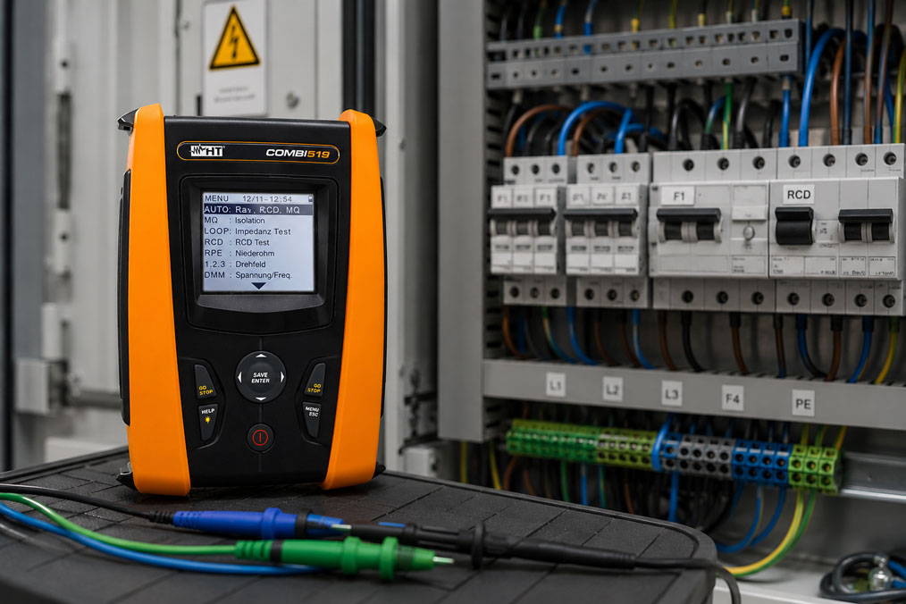
The COMBI519 installation tester is suitable for more extensive test tasks requiring, among other things, protective conductor testing, insulation measurement, RCD testing, line and loop impedance, short-circuit current display, phase sequence and documentation. It is particularly relevant when RCD Type B or EV must be taken into account in addition to standard tests.
The COMBI521 installation tester is a suitable choice when modern documentation and communication functions as well as EVSE test procedures for charging infrastructure also play a role. In installations where classic installation tests and tests on charging points are combined, such a device can significantly structure the test procedure.
However, for TT, TN and IT systems, one point remains important: the measuring instrument must fit the task, but evaluation depends on the network system. Especially in IT systems, medical areas, industrial special networks or unclear existing installations, it should always be clarified before testing which protective measure is actually applied and which additional test equipment or documentation is required.
| Product / area | Typical use | Particularly relevant for |
|---|---|---|
| Installation testers / installation testing VDE 0100 | Selection of suitable test instruments for electrical installations | VDE testing, protective measures, existing installations, industry and documentation |
| EASYTEST installation tester | Installation tester with auto sequence function | Recurring test procedures, electrical installations and structured on-site testing |
| COMBI519 installation tester | Multifunction installation tester with RCD Type B and auto sequence | Protective conductor, insulation measurement, RCD testing, loop impedance, short-circuit current and phase sequence |
| COMBI521 installation tester | Installation tester with auto sequence, RCD Type B, Wi-Fi and EVSE test procedure | Charging infrastructure, extensive documentation, modern test procedures and installation testing |
Conclusion: the test procedure starts with assessing the network system
TT, TN and IT systems differ not only in their wiring, but above all in their protection philosophy. For this reason, a test procedure must not be transferred blindly from one installation to another. Loop impedance, RCD testing, earth resistance, insulation measurement and insulation monitoring have different meanings depending on the network system.
In the TT system, the earthing system and RCD effectiveness are particularly in focus. In TN-S and TN-C-S systems, protective conductor continuity, loop impedance and short-circuit current are central variables. In the IT system, insulation monitoring is decisive because the first fault is deliberately treated differently than in earthed systems.
The most important recommendation is: before testing, the network system must be clearly identified and documented. Only then can the measuring functions of the installation tester be selected appropriately and the results evaluated correctly. Especially in existing installations, industrial plants and special networks, this preliminary work saves a great deal of troubleshooting and prevents dangerous misinterpretations.
FAQ: frequently asked questions about testing TT, TN and IT systems
Why does the network system affect the test procedure?
The network system determines how the fault current flows and which protective measure becomes effective. In a TN system, loop impedance is particularly important for automatic disconnection. In a TT system, the focus is usually on the combination of earthing system and RCD. In an IT system, insulation monitoring is decisive.
What is the most important difference between TT and TN systems?
In a TN system, the protective conductor or PEN conductor is connected to the earthed power source, creating a low-impedance fault current path. In a TT system, the consumer installation has its own earthing system, and the fault current flows back via earth. This makes RCDs particularly important in TT systems.
Why is loop impedance measurement so important in a TN system?
Loop impedance influences the fault current in the event of a fault to an exposed conductive part. If the impedance is low enough, a sufficiently high current can flow so that a fuse or circuit breaker disconnects within the required time. It is therefore a central value for evaluating disconnection conditions in TN systems.
Why is an RCD often required in a TT system?
In a TT system, the fault current is often too small due to the earth path to trip a fuse or circuit breaker quickly enough. An RCD detects the residual current and disconnects when the rated residual operating current is exceeded. This makes RCD testing particularly important in TT systems.
What is particularly critical in TN-C-S installations?
The critical point is the separation of the PEN conductor into neutral conductor and protective conductor. After this separation, N and PE must not be reconnected arbitrarily. Faulty N/PE bridges, PEN problems or stray currents can lead to dangerous conditions and implausible measured values.
Can an installation tester automatically detect whether TT, TN or IT is present?
An installation tester can measure many electrical quantities and partly provide indications. However, safe evaluation of the network system requires visual inspection, documentation, knowledge of the supply, protective conductor routing, earthing and installation structure. The network type should not be derived from a single measured value alone.
Why is testing different in an IT system?
In an IT system, the first insulation fault normally does not lead to a high fault current and does not necessarily result in immediate disconnection. Instead, insulation monitoring must detect and report the fault. Only at the second fault can other disconnection conditions become relevant. Therefore, an IT system must not be evaluated like a TN system.
What is tested particularly in an IT network?
Particularly important are the insulation condition, function of the insulation monitoring device, reporting of the first fault, protective conductor and equipotential bonding connections and behavior in the fault case according to the documented protection concept. Depending on the installation, additional tests and special standard requirements may apply.
Why can measured values in existing installations appear implausible?
Existing installations have often been extended, converted or partially modernized. Documentation and actual implementation do not always match. Different network sections, subsequent N/PE connections, old PEN routing or additional earth connections can make measured values appear contradictory at first.
What does high loop impedance mean in a TT system?
High loop impedance in a TT system must not automatically be evaluated in the same way as in a TN system. Since the fault current path runs via earth, the earthing system and RCD effectiveness are the main focus. The decisive factor is whether the protective measure in the TT system is effective as a whole.
May the same auto sequence be used in every network system?
Not without checking. Auto sequences can be very helpful when they match the installation and the protection concept. In special networks, IT systems or unclear existing installations, however, it must be checked whether the automatic order and evaluation of measured values fit the network system.
What role does insulation measurement play?
Insulation measurement is important in all network systems because it provides indications of insulation faults, moisture, damaged cables or faulty equipment. In IT systems, the insulation condition is particularly closely linked to the protection philosophy because the first fault must be detected and corrected.
Why do RCDs sometimes trip unexpectedly during testing or operation?
Causes can include real fault currents, leakage currents from several devices, N/PE connections, incorrectly assigned neutral conductors, EMC filters, moisture or an unsuitable selection of RCD type. Troubleshooting should always include circuit assignment, neutral conductor routing and connected loads.
Which documents are helpful before testing?
Helpful documents include circuit diagrams, distribution board plans, network system information, earthing and equipotential bonding documentation, information on RCDs, protective devices, transformers, insulation monitoring and special areas. In existing installations, these documents should be compared with the actual implementation.
Which installation tester is suitable for TT, TN and IT systems?
This depends on the installation and the required measuring functions. For many VDE 0100 test tasks, multifunction installation testers with protective conductor testing, insulation measurement, RCD test, loop impedance and documentation are useful. In IT systems or special installations, it must also be checked whether the device and the test procedure fit the protective measure.
What is the most important rule when testing different network systems?
The most important rule is: first clearly identify the network system and the protective measure, then measure and evaluate. A measured value is meaningful only in the correct network system context. Without this classification, even correctly measured values can be misinterpreted.