


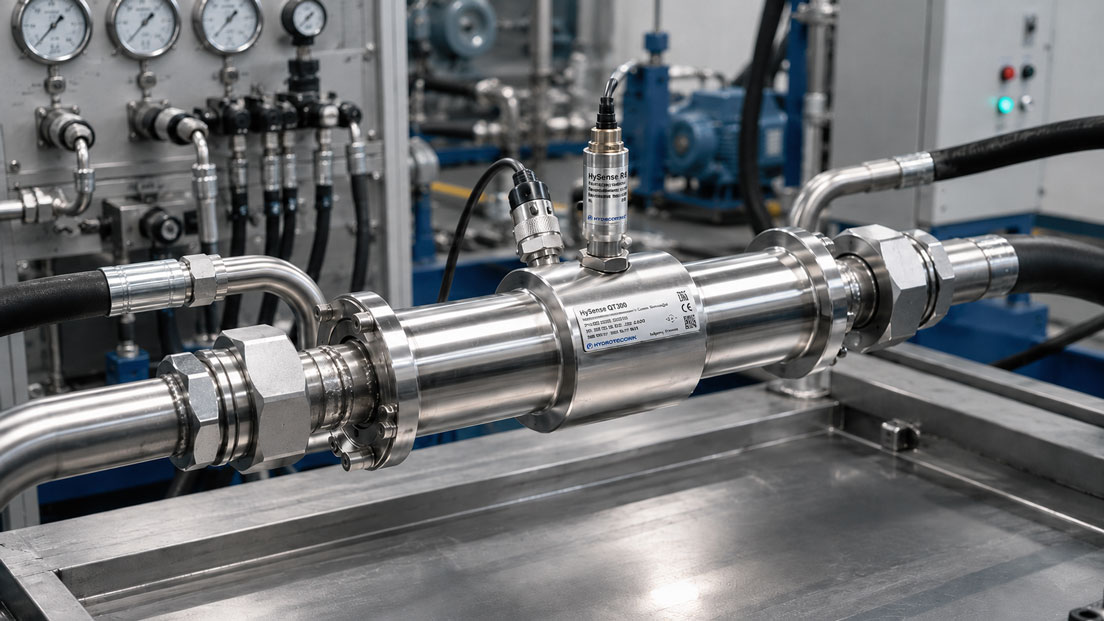
Turbine flow meters are frequently used for fast volumetric flow measurement in hydraulic systems, test benches and mobile machinery. In many applications, the medium flows continuously in one defined direction. However, there are numerous circuits in which the direction of flow reverses during operation.
Typical examples include the testing of double-acting hydraulic cylinders, reversible pumps, hydrostatic drives and test benches with changing load conditions. In these applications, knowing only the magnitude of the volumetric flow is not always sufficient. For the evaluation, it may be equally important to know whether the oil is currently flowing forwards or backwards through the measuring point.
However, a turbine whose rotor can turn in both directions does not automatically provide an unambiguous direction signal. At the same volumetric flow rate, a single frequency output usually generates the same frequency regardless of the direction in which the medium is flowing.
For genuine bidirectional measurement, the mechanical suitability, calibration and electrical direction detection must therefore be considered together.
Table of contents
- What bidirectional flow measurement means
- How a turbine flow meter measures volumetric flow
- When forward and reverse flow are relevant
- Distinguishing mechanical suitability from direction detection
- Which output signals can transmit the direction
- Direction detection using two phase-shifted signals
- K-factor and calibration for both directions
- Installation direction and straight pipe runs
- Considering pressure loss and measuring range
- Rapid direction changes and zero crossing
- Evaluating bidirectional signals in the PLC
- Systematic commissioning
- Typical errors and misinterpretations
- Practical example: Hydraulic cylinder on a test bench
- Which measuring instruments / products are suitable?
- Conclusion
- Frequently asked questions about bidirectional turbine flow meters
What bidirectional flow measurement means
At a bidirectional measuring point, the medium can flow through the sensor in both directions. The evaluation must detect at least the current volumetric flow and, where required, the respective direction of flow.
Depending on the application, different results may be required:
- only the absolute volumetric flow, irrespective of direction
- volumetric flow with a positive or negative sign
- separate totalisation of forward and reverse flow
- a net totaliser calculated from forward flow minus reverse flow
- a separate direction signal for control or diagnostics
These requirements should be defined before the sensor is selected. A turbine that may be hydraulically exposed to flow in both directions does not necessarily support all of the evaluation methods listed above.
How a turbine flow meter measures volumetric flow
In a turbine flow meter, the flow energy of the medium sets a turbine rotor in motion. Within the specified range, the rotational speed of the rotor is approximately proportional to the volumetric flow.
A magnetic or electronic pickup detects the passing turbine blades and generates a sequence of electrical pulses. The instantaneous volumetric flow can be calculated from the frequency:
Q = f ÷ K
Where:
- Q is the volumetric flow
- f is the measured frequency
- K is the calibration or K-factor in pulses per unit of volume
If the pulses are counted over time, the total volume that has passed through the sensor can also be determined.
However, a single pickup initially detects only how fast the turbine rotor is turning. If it rotates at the same speed in the opposite direction, the output frequency may be almost identical. The direction information is missing.
When forward and reverse flow are relevant
Bidirectional flow measurement is particularly useful in hydraulic circuits whose working direction changes regularly.
Typical applications include:
- test benches for double-acting hydraulic cylinders
- reversible hydraulic motors and hydrostatic drives
- pump test benches with changing operating conditions
- steering and drive hydraulics in mobile machinery
- accumulator charging and discharging processes
- cooling and lubrication circuits with reverse flow
- flushing processes with alternating flow direction
- measurement of leakage or return-flow quantities
On a cylinder test bench, for example, forward flow may represent the extension movement and reverse flow the retraction movement. If both directions are recorded separately, the cylinder speed, volume balance and internal leakage can be assessed more accurately.
Distinguishing mechanical suitability from direction detection
When selecting a product, three different characteristics must be distinguished from one another.
1. Flow in both directions
The sensor may be exposed mechanically to flow from either side. The bearings, turbine rotor and internal flow path must be suitable for this.
2. Measurement in both directions
The sensor has defined measuring ranges and calibration characteristics for both forward and reverse flow. A rotor may be capable of rotating backwards without the specified measuring accuracy being guaranteed in that direction.
3. Detection of the flow direction
The electrical signal contains information about the direction in which the medium is flowing. This may require two frequency channels, a separate direction signal or a digital measured value with a sign.
The description “suitable for bidirectional operation” should therefore always be clarified technically. The decisive question is whether only alternating flow through the sensor is permitted or whether a direction-dependent measured value is also required.
Which output signals can transmit the direction
| Output signal | Volumetric flow | Direction detection |
|---|---|---|
| Single frequency signal | Very suitable for dynamic measurements | Normally not unambiguous |
| Two phase-shifted frequency signals | High temporal resolution | Possible through the signal sequence |
| 4–20 mA | Simple analogue transmission | With conventional 4–20 mA scaling, usually only the magnitude |
| Separate switching output | Volumetric flow via the main signal | Direction as an additional binary state |
| CAN or another bus signal | Digital measured value and diagnostics | As a sign or status, depending on the device protocol |
A conventional 4–20 mA signal is only suitable to a limited extent for genuine positive and negative scaling. If 4 mA represents maximum reverse flow, 12 mA represents zero flow and 20 mA represents maximum forward flow, only part of the signal range is available for each direction.
For this reason, a magnitude signal combined with a separate direction signal or a digital interface is often used instead.
Direction detection using two phase-shifted signals
A common direction-detection principle uses two pickup channels. Both generate frequency signals that are phase-shifted by approximately 90 degrees relative to one another.
In the first direction of flow, the rising edge of channel 1 occurs before the corresponding edge of channel 2. If the rotor turns in the opposite direction, channel 2 leads.
The evaluation therefore determines:
- the volumetric flow from the frequency
- the direction from the sequence of the signal edges
This method is frequently referred to as a quadrature or A/B signal. It is comparable to direction detection with rotary encoders.
The PLC or evaluation unit must be capable of recording both channels at a sufficiently high speed. A conventional slow digital input module may be unsuitable at high pulse frequencies. In that case, a high-speed counter, frequency input or dedicated measuring module is required.
K-factor and calibration for both directions
Even with symmetrically designed sensors, the measuring characteristics in the forward and reverse directions may differ slightly. Possible causes include manufacturing tolerances, the bearing arrangement, internal flow guidance and the position of the pickups.
For precise measurements, a separate K-factor for each direction may therefore be useful:
- K-factor for forward flow
- K-factor for reverse flow
If the sensor is calibrated in only one direction and the same factor is used for reverse flow, the achievable accuracy in the reverse direction may be lower.
When ordering, it should therefore be clarified whether:
- only the preferred direction of flow is calibrated
- calibration in both directions is possible
- separate calibration data are supplied for both directions
- the medium and viscosity of the subsequent application are taken into account
Viscosity has a particular influence on the starting behaviour and characteristic curve of turbine flow meters. Calibration with a low-viscosity fluid may produce different results when the sensor is later used with more viscous hydraulic oil.
Installation direction and straight pipe runs
Even a turbine flow meter suitable for bidirectional operation often has a preferred direction of flow or a direction marked on the rating plate. This may be relevant for the standard calibration or the electrical sign convention.
When the direction of flow changes, the inlet and outlet sides also change. A pipe section that serves as an upstream straight run during forward flow is located downstream of the sensor during reverse flow.
To achieve comparable measuring quality in both directions, the installation should therefore be designed as symmetrically as possible. Strong flow disturbances immediately upstream of only one side of the sensor should be avoided.
Particularly critical conditions include:
- tight pipe bends directly next to the sensor
- partially opened valves
- large changes in cross-section
- pump connections that generate swirl
- air bubbles or incompletely filled pipes
The specific requirements for upstream and downstream straight pipe runs depend on the respective turbine flow meter and the manufacturer’s documentation.
Considering pressure loss and measuring range
The turbine rotor must be accelerated by the flow. A turbine flow meter therefore causes a certain pressure loss, which increases with volumetric flow, viscosity and sensor size.
A sensor selected too small may provide high resolution but can cause an unacceptably high differential pressure at maximum flow.
A sensor selected too large reduces the pressure loss but may operate outside its calibrated range at low volumetric flow rates. The rotor may then start unevenly or remain stationary.
For bidirectional applications, at least the following must therefore be checked:
- minimum volumetric flow in both directions
- maximum volumetric flow and short-term peaks
- viscosity at the minimum and maximum temperature
- permissible operating pressure
- pressure loss at maximum volumetric flow
Rapid direction changes and zero crossing
When the direction changes, the turbine rotor is first decelerated, briefly comes to a standstill and is then accelerated in the opposite direction.
During this transition, the displayed volumetric flow may temporarily deviate from the actual dynamic flow. The inertia of the rotor, bearing friction and pickup principle determine how quickly the sensor can follow the direction change.
Individual pulses or alternating direction signals may also occur directly around the zero point. The evaluation should therefore include a suitable zero zone or temporal plausibility check.
However, a zero zone that is too large suppresses genuine small reverse flows. A zero zone that is too small may cause the signal to switch continuously between forward and reverse flow when pulsations occur.
For highly dynamic test benches, the response time, minimum frequency and behaviour during direction changes should therefore be checked explicitly.
Evaluating bidirectional signals in the PLC
A suitable PLC evaluation should process the magnitude and direction separately.
With two phase-shifted frequency channels, the sequence can be simplified as follows:
- Record the edges of channel A and channel B.
- Determine which channel is leading.
- Convert the frequency into a volumetric flow.
- Assign a positive or negative sign depending on the direction.
- Totalise forward and reverse flow separately.
- If required, calculate the net volume from both totals.
Different K-factors can be stored for the calculation:
Qforward = f ÷ Kforward
Qreverse = −f ÷ Kreverse
Diagnostic states should also be provided. Implausible conditions would include a frequency on only one channel, a permanently undefined phase relationship or a signal outside the specified frequency range.
Systematic commissioning
- Define the direction of flow: Specify which direction is considered positive.
- Check the sensor: Verify the measuring range, medium, viscosity, pressure and signal version.
- Check the installation: Verify the markings, straight pipe runs and complete filling of the pipe.
- Test the electrical signals: Check the frequency channels, power supply and, where applicable, CAN communication.
- Generate forward flow: Compare the measured value, sign and K-factor with a known operating point.
- Generate reverse flow: Check the direction change and the K-factor applicable to reverse flow.
- Check the zero crossing: Observe the behaviour at standstill and during a slow direction reversal.
- Test the totalisers: Check the plausibility of forward, reverse and net volume.
Commissioning should not be performed only at maximum flow. Low volumetric flow rates and the range around the direction change are particularly important for determining whether the sensor and evaluation are suitable for the measuring task.
Typical errors and misinterpretations
| Error | Possible consequence | Better approach |
|---|---|---|
| A single frequency channel is used as a bidirectional signal | Forward and reverse flow cannot be distinguished | Use two direction channels or a digital direction signal |
| Mechanical reverse rotation is treated as calibrated reverse measurement | Unknown measuring deviation during reverse flow | Request calibration for both directions |
| Only one K-factor is stored | One direction may show a systematic deviation | Use direction-specific calibration data |
| 4–20 mA is evaluated without a direction signal | Reverse flow appears as positive volumetric flow | Transmit the direction separately or use a bus signal |
| A straight pipe run is provided on only one side | Different measuring quality depending on the direction | Design the measuring point as symmetrically as possible |
| Pulsation is interpreted as a genuine direction change | Unstable sign and incorrect totalisation | Define a zero zone and temporal plausibility check |
| Sensor selected too large | Small reverse flows are not detected | Consider the minimum volumetric flow during selection |
Practical example: Hydraulic cylinder on a test bench
A double-acting hydraulic cylinder is to be tested on a test bench. The turbine flow meter is installed in a line through which oil flows towards the cylinder during extension and in the opposite direction during retraction.
Initially, a turbine flow meter with a single frequency output is used. The test software displays positive values in both directions of movement. The volumetric flow values are plausible, but automatic assignment to the cylinder movement is not possible.
For the revised measuring point, a sensor and evaluation combination suitable for bidirectional operation with direction detection is selected. The software receives a positive volumetric flow during extension and a negative volumetric flow during retraction.
In addition, the forward and reverse volumes are integrated separately. This reveals that the returning volume differs slightly from the supplied volume. Together with the piston-rod geometry and an additional pressure measurement, it can then be assessed whether the difference is due to the design or indicates internal leakage.
When the directional control valve is switched slowly, brief small direction changes occur. A suitably defined zero zone suppresses individual pulsation pulses without eliminating the genuine reverse flow during the cylinder movement.
Which measuring instruments / products are suitable?
The turbine flow meters category contains turbine flow sensors for mobile and stationary measurements in hydraulic, test-bench and industrial applications.
Further measuring principles and solutions can be found in the flow measurement technology category.
HySense® QT3xx for high volumetric flow rates with an SAE flange
The HySense® QT3xx is designed for larger hydraulic lines and has a 2-inch SAE flange connection.
The series is suitable for dynamic volumetric flow measurements with low flow resistance. The required output and direction-detection version must be selected to match the evaluation system.
HySense® QT4xx for robust heavy-duty applications
The HySense® QT4xx is a robust turbine flow meter designed for high mechanical and hydraulic loads.
Depending on the version, frequency, analogue or CAN signals are available. Whether separate direction detection is required and supported must be checked for the specific ordered version.
HySense® QT5xx for different measuring ranges and media
The HySense® QT5xx is available in aluminium and stainless-steel versions and is suitable for precise volumetric flow measurements in hydraulic applications.
For changing flow directions, the measuring range, calibration viscosity, output signal and required direction information must be defined.
HySense® QT6xx for dynamic hydraulic measurements
The HySense® QT6xx series is designed for precise and fast volumetric flow measurements with different hydraulic fluids and varying temperatures.
Its short response time and low flow resistance make it suitable for mobile measurements and test benches, among other applications. For bidirectional use, the specific sensor, calibration and evaluation combination must be defined together.
When another measuring principle may be more suitable
If very low volumetric flow rates, high viscosity or particularly unambiguous direction detection are the main priorities, a gear or positive-displacement flow sensor may be more suitable than a turbine flow meter.
ICS Schneider Messtechnik assists with selecting the measuring principle, measuring range, output signal and evaluation instrument. The medium, viscosity, temperature, pressure, minimum and maximum volumetric flow, pipe connection and requirements concerning direction detection and response time are required for the design.
Conclusion: Bidirectional flow capability alone is not sufficient
A turbine flow meter can be mechanically suitable for forward and reverse flow without electrically detecting the direction of flow. A single frequency or standard signal frequently transmits only the magnitude of the volumetric flow.
Unambiguous direction detection requires, for example, two phase-shifted frequency channels, a separate direction signal or a digital measured value with a sign.
For precise applications, the turbine flow meter should be calibrated in both directions. Different K-factors for forward and reverse flow can compensate for possible differences between the two characteristic curves.
The installation must also be suitable for both directions. Flow disturbances, straight pipe runs, viscosity, pressure loss and minimum volumetric flow influence the measuring quality.
Particular attention must be paid to direction changes. Rotor inertia, pulsations and signals near the zero point can result in false direction changes or incorrect totaliser values without suitable evaluation logic.
The appropriate solution therefore consists of the complete system comprising the turbine flow meter, calibration, signal transmission and PLC or measuring-instrument evaluation.
Frequently asked questions about bidirectional turbine flow meters
Can every turbine flow meter measure in both directions?
No. The manufacturer must confirm the mechanical suitability, measuring range and, where applicable, calibration for both directions.
Can a single frequency output detect the direction of flow?
Normally not. At the same rotor speed, the same frequency can be generated in both directions.
How is the direction detected using two frequency signals?
The two signals are phase-shifted relative to one another. The evaluation detects the direction of rotor rotation from the sequence of their edges.
Can a 4–20 mA signal represent forward and reverse flow?
Only with a dedicated scaling or an additional direction signal. A conventional 4–20 mA signal usually represents only the positive magnitude.
Are different K-factors required for both directions?
This may be useful for higher accuracy requirements because the measuring characteristics in the forward and reverse directions can differ.
What happens when the direction changes?
The turbine rotor is first decelerated and then accelerated in the opposite direction. During this process, the measured value may be briefly delayed or unstable.
How can false direction changes caused by pulsations be prevented?
The evaluation can use a suitable zero zone, minimum frequency or temporal plausibility check. However, this must not suppress genuine small reverse flows.
Are straight pipe runs required on both sides?
For changing flow directions, an installation that is as symmetrical as possible is advantageous because each side alternately becomes the inlet side.
Which PLC inputs are required for quadrature signals?
Two high-speed counter or frequency inputs that can reliably detect the sequence of the signal edges are generally required.
When is a gear flow sensor more suitable?
A gear or positive-displacement flow sensor may be advantageous for very low volumetric flow rates, higher viscosity or particularly demanding requirements concerning direction detection and volumetric resolution.
Which information does ICS Schneider require for selection?
The medium, viscosity, temperature, operating pressure, minimum and maximum volumetric flow in both directions, connection, required output signal, response time and requirements concerning calibration and direction detection are needed.