


In injection moulding, the melt pressure changes within fractions of a second. During injection, switchover and holding pressure, rapid pressure increases and sometimes high pressure peaks occur. A melt pressure sensor in the nozzle or hot-runner area must measure these processes reproducibly, even though very high temperatures act on its sensor tip at the same time.
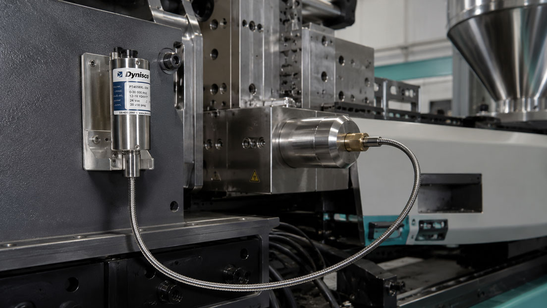
The measuring point differs significantly from a conventional pressure measurement on an extruder. Installation space in the mould and around the machine nozzle is often severely restricted. Compact sensors with a small diaphragm, slim sensor tip, flexible capillary line and protected connecting cable are therefore used.
A small diaphragm improves access to the melt and can reproduce rapid pressure changes effectively. However, it is more sensitive to installation errors, lateral forces, hardened plastic residues and mechanical overload. A correctly manufactured measuring bore and the proper installation depth are therefore just as important as the measuring range, output signal and temperature limit.
This article explains how melt pressure sensors for hot runners, nozzles and injection moulds are selected, installed and used to monitor the process window.
Table of contents
- Where pressure can be measured in injection moulding
- What information the pressure profile provides
- Why a small diaphragm presents special requirements
- Capturing rapid pressure increases and pressure peaks
- High melt temperatures and temperature compensation
- Selecting the measuring range and overload resistance
- Measuring bore, installation depth and mounting
- Capillary line, cable protection and electronics temperature
- Selecting mV/V, voltage or 4–20 mA
- Process window and cycle monitoring
- Correctly interpreting typical fault patterns
- Cleaning, zero-point check and maintenance
- Practical example: Fluctuating switchover pressure in the hot runner
- Which measuring instruments / products are suitable?
- Conclusion
- Frequently asked questions about melt pressure sensors in hot runners
Where pressure can be measured in injection moulding
Different pressure variables are considered in injection moulding. They must not be confused with one another.
| Measuring point | Measured variable | Typical information |
|---|---|---|
| Hydraulic system of the machine | Hydraulic or injection pressure | Load and function of the machine drive |
| Machine nozzle | Melt pressure upstream of the mould | Pressure build-up, material flow and reproducibility of the injection process |
| Hot runner | Melt pressure within the manifold or nozzle area | Pressure losses, flow resistance and function of the hot-runner system |
| Mould cavity | Internal mould pressure or cavity pressure | Mould filling, holding-pressure effect and component quality |
A melt pressure sensor in the machine nozzle does not automatically measure the actual pressure in the cavity. Between the two measuring points are the sprue, hot runner, nozzles, gates and the progressively filling mould. Each of these points causes a pressure loss that depends on time and material.
A nozzle or hot-runner sensor is very useful for monitoring the melt as it enters the mould. If the behaviour directly inside the moulded part is to be assessed, however, a measuring system specifically designed for cavity pressure is normally required.
What information the pressure profile provides
A single maximum pressure value shows only a small part of the process. The complete pressure curve over the injection cycle is more informative.
Typical phases include:
- pressure increase during injection
- switchover point from velocity control to pressure control
- holding-pressure phase
- pressure reduction during solidification and cooling
- pressure-free phase before the next cycle
Deviations in the pressure profile can indicate:
- fluctuating material viscosity
- different melt temperatures
- changed injection velocity
- blocked or restricted hot-runner nozzles
- worn non-return valves
- deviating switchover points
- insufficient mould venting
For a reliable assessment, pressure, screw position, velocity and other process variables must be recorded synchronously. Only then can it be determined whether a pressure change is the cause or the result of another process deviation.
Why a small diaphragm presents special requirements
Only limited space is often available in nozzles and hot runners. A small diaphragm mounted as flush as possible with the internal contour enables direct pressure transmission without unnecessarily restricting the flow channel.
The compact diaphragm responds to very small changes in volume. At the same time, it can be sensitive to mechanical influences.
Particularly critical conditions include:
- a measuring bore that is too deep, causing the diaphragm to protrude
- a bore that is too short, creating a dead volume in front of the diaphragm
- lateral loading during installation
- excessive tightening torque
- hardened plastic residues in the measuring bore
- cleaning with hard or pointed tools
A protruding diaphragm can be subjected directly to the melt flow and mechanical stress during cleaning. A diaphragm mounted too far back, on the other hand, creates a small cavity in which material remains, ages or solidifies. This can slow down the response.
The measuring bore must therefore be manufactured according to the dimensional drawing of the specific sensor model and checked using suitable gauges.
Capturing rapid pressure increases and pressure peaks
Injection-moulding processes are significantly more dynamic than many continuous extrusion processes. During injection, the pressure can rise from almost zero to several hundred or more than one thousand bar within a very short time.
For capturing such processes, not only the sensor accuracy but also the following characteristics are important:
- mechanical response time of the diaphragm
- signal bandwidth of the sensor and amplifier
- sampling rate of the data-acquisition system
- filter settings in the control system or software
- time synchronisation with the machine cycle
Very strong averaging produces a stable measured value but can suppress brief pressure peaks. Unfiltered recording at a high sampling rate, on the other hand, can make electrical interference and mechanical vibrations more visible.
The filtering should therefore suit the actual evaluation task. Moderate smoothing may be useful for basic process monitoring. Higher temporal resolution is required for investigating pressure peaks, switchover processes or rapid valve movements.
High melt temperatures and temperature compensation
The sensor tip is in direct contact with the hot plastic melt. However, the strain-gauge electronics or the actual measuring element usually must not be exposed continuously to this temperature.
In conventional melt pressure sensors, the pressure is therefore transmitted through a filled capillary from the hot diaphragm to a thermally isolated measuring element. The length and design of the stem or flexible capillary line protect the more sensitive electronics from the process temperature.
Temperature nevertheless influences the measurement. Possible effects include:
- zero-point shift during heating
- changed sensitivity
- slow drift during thermal stabilisation
- different output values after cold and warm starts
Zero adjustment should therefore only be performed after the mould, hot runner and sensor have reached a stable operating condition and no process pressure is acting on the diaphragm.
Adjustment with a cold mould may result in a visible zero-point shift after heating. However, the sensor should not simply be set to zero while residual pressure is present, as this would mathematically suppress the actual process pressure.
Selecting the measuring range and overload resistance
The measuring range should be selected as low as possible but as high as necessary. A measuring range that is too large reduces the usable resolution for the normal process pressure. A measuring range that is too small can be overloaded by pressure peaks.
At least the following must be known for selection:
- typical injection or melt pressure
- maximum expected process pressure
- brief pressure peaks
- possible pressure with a blocked nozzle
- permissible sensor overpressure
The overpressure specification must not be used as the regular operating range. Repeated pressure peaks above the nominal measuring range can permanently stress the diaphragm and transmission medium, even if the sensor does not fail immediately.
Fatigue loading is also relevant in highly cyclic processes. An application involving thousands or millions of load cycles presents different requirements from an occasional static pressure test.
Measuring bore, installation depth and mounting
The mounting quality directly affects the measuring behaviour and service life. The bore must be aligned, clean and free from burrs. In particular, the sealing seat and the front section of the measuring bore must comply with the manufacturer’s specification.
The following points are important during mounting:
- Check the bore: Verify the diameter, depth, thread and sealing seat.
- Clean the measuring channel: Remove plastic residues and metal chips completely.
- Insert the sensor straight: Do not apply lateral forces to the tip or capillary.
- Use the locknut: Secure the sensor in accordance with the intended design.
- Observe the tightening torque: Do not exceed the manufacturer’s value.
- Check the installation position: Position the diaphragm flush and without a disruptive dead volume.
Installing the sensor by turning the electronics housing or twisting the flexible capillary line can damage it. The designated spanner flats and locknuts must be used.
When replacing a sensor, the existing measuring bore should be checked again. Plastic deposits or damage to the sealing seat may cause the new sensor to be subjected to incorrect loading during installation.
Capillary line, cable protection and electronics temperature
In the mould area, the sensor is exposed not only to high temperatures but also to vibrations, moving machine parts, cleaning work and tight bending radii.
The flexible line between the sensor tip and electronics must therefore not:
- be kinked or crushed
- rub against sharp mould edges
- lie directly against heating elements
- be loaded by moving platens or ejectors
- be installed under tensile stress
The specified minimum bending radius must be observed. A tight loop directly behind the sensor tip can damage the internal capillary.
The electronics housing also requires sufficient distance from the hot mould. If the permissible ambient temperature is exceeded, the zero point, sensitivity and service life may be affected even though the diaphragm temperature itself is still within specification.
Selecting mV/V, voltage or 4–20 mA
Conventional melt pressure sensors frequently provide an mV/V signal from a strain-gauge measuring bridge. This signal requires a suitable measuring amplifier but enables direct and fast acquisition.
Versions with an integrated amplifier provide, for example:
- 0–5 V
- 0–10 V
- 4–20 mA
An amplified signal simplifies connection to a PLC, data-acquisition system or process-monitoring system. A 4–20 mA signal is particularly resistant to interference over longer cable runs. For very fast pressure curves, however, the transmitter bandwidth and sampling rate of the analogue input must also be checked.
For a 4–20 mA sensor, the complete measuring chain should be checked before commissioning. The UPS4E loop calibrator can be used to check or simulate the PLC input, scaling and cable function.
However, a loop check does not test the mechanical function of the melt pressure diaphragm. The sensor itself must be assessed using the zero point, shunt calibration and, where necessary, a pressure calibration.
Process window and cycle monitoring
A melt pressure sensor can provide characteristic values for every injection cycle. These include:
- maximum melt pressure
- pressure at the switchover point
- pressure integral over the injection or holding-pressure phase
- rate of pressure increase
- time of maximum pressure
- residual pressure at the end of the cycle
Reference cycles are first determined from a stable process. Upper and lower tolerance limits can then be derived from them. If a later cycle deviates significantly, the moulded part can be rejected or the process adjusted automatically.
Limit values should not be taken from a single sample cycle alone. The material batch, mould temperature, machine condition and permissible component tolerances must be taken into account.
Trend comparison is particularly valuable. A slowly increasing pressure peak, for example, can indicate growing deposits, a narrowing nozzle or changed material viscosity.
Correctly interpreting typical fault patterns
| Observation | Possible cause | Check |
|---|---|---|
| Zero point changes during heating | Thermal influence or adjustment in the cold condition | Allow thermal stabilisation and verify the pressure-free condition |
| Pressure profile responds unusually slowly | Dead volume, solidified melt or strong signal filtering | Check the measuring bore and data acquisition |
| Peak occurs only in individual cycles | Process deviation, electrical interference or mechanical impulse | Compare with screw position and machine condition |
| Sensor continuously shows high residual pressure | Material in front of the diaphragm, zero-point error or diaphragm damage | Allow the mould to cool safely and inspect the measuring point professionally |
| Signal fails completely | Cable damage, connector, power supply or sensor failure | Check the electrical measuring chain and shunt signal |
| Measured value jumps when the mould moves | Crushed cable, loose connector or mechanical loading | Check the cable routing and strain relief |
Cleaning, zero-point check and maintenance
The diaphragm must not be cleaned with screwdrivers, drills, wire brushes or other hard tools. Even small scratches or deformations can impair the measurement.
Plastic residues should only be removed using a method approved by the manufacturer. The material type, cleaning temperature and diaphragm material must be taken into account.
A recurring check should include:
- visual inspection of the tip and thread
- inspection of the cable, protective hose and connectors
- zero-point check in a pressure-free condition
- check of the internal shunt calibration, where available
- comparison of typical cycle values with reference data
The shunt calibration generates an electrical reference signal and checks a large part of the signal chain. However, it does not replace a complete pressure calibration and does not detect every form of mechanical diaphragm damage.
Practical example: Fluctuating switchover pressure in the hot runner
In a multi-cavity mould, the moulded-part weight fluctuates even though the machine parameters and metering stroke appear unchanged. A melt pressure sensor in the nozzle area shows that the pressure at the switchover from injection velocity to holding pressure varies from cycle to cycle.
A sensor fault is initially suspected. However, the zero point and shunt calibration are stable. The pressure signal also behaves reproducibly during the remaining phases of the cycle.
Joint evaluation of the pressure curve and screw position shows that the pressure deviation occurs shortly before the switchover point in each case. Inspection of the machine identifies a worn non-return valve.
After maintenance, the pressure increase and switchover point are significantly more consistent. At the same time, the variation in moulded-part weight is reduced.
The example shows that a hot-runner or nozzle pressure sensor does more than provide a maximum value. The pressure curve over time can reveal process deviations that would not be visible from the configured machine parameters alone.
Which measuring instruments / products are suitable?
The sensors for injection moulding category contains sensors for measuring melt pressure as well as hydraulic machine and injection pressures.
Further versions for plastics processing and extrusion are available in the Dynisco melt pressure sensors category.
Dynisco PT465XL for nozzles and hot runners
The Dynisco PT465XL is specifically designed for measuring plastic melt pressure at injection-moulding nozzles and in hot-runner applications.
The compact design with a flexible, protected line simplifies installation in confined mould and nozzle areas. The mV/V output signal is suitable for fast measurements using an appropriate strain-gauge amplifier.
Dynisco PT4654XL with 4–20 mA output
The Dynisco PT4654XL has an integrated measuring amplifier and provides a standardised 4–20 mA signal.
This version is particularly suitable when the melt pressure is to be transmitted directly to a PLC, process control system or industrial data-acquisition system.
Dynisco PT467XL for particularly restricted installation space
The Dynisco PT467XL is designed for applications with very limited installation space. Its flexibly positionable capillary line simplifies integration into compact moulds and machine areas.
Do not confuse hydraulic-pressure sensors with melt pressure sensors
The Dynisco PT130, PT140, PT150 and PT160 sensors measure the hydraulic pressure of the injection-moulding machine. They are suitable for monitoring the injection ram, hydraulic system and clamping system but are not in direct contact with the hot plastic melt.
ICS Schneider Messtechnik assists with selecting the measuring range, output signal, insertion length and accessories. The melt temperature, expected pressure, measuring point, thread, available installation depth, cable route and required signal processing are needed for the design.
Conclusion: The sensor must match the dynamics and installation conditions of the hot runner
Melt pressure sensors on nozzles and hot runners capture rapid pressure changes directly upstream of or inside the mould. They therefore provide important information about injection, switchover, holding pressure and the stability of the injection-moulding process.
The small diaphragm enables compact and dynamic measurement but is sensitive to incorrect bore depth, lateral loading, excessive tightening torque and improper cleaning.
High melt temperatures are managed by the design comprising the diaphragm, capillary and thermally isolated measuring element. Nevertheless, both the diaphragm and electronics temperatures as well as thermal zero-point shift must be taken into account.
The measuring range and overload resistance must suit both the normal process pressure and possible pressure peaks. Signal bandwidth, sampling rate and filtering are also decisive for process analysis.
The most reliable measuring point is achieved when the sensor, measuring bore, cable route, output signal and data acquisition are defined together during the mould-design phase.
Frequently asked questions about melt pressure sensors in hot runners
What does a melt pressure sensor measure in a hot runner?
It measures the pressure of the plastic melt in the hot runner, at the nozzle or immediately before the melt enters the mould.
Is melt pressure the same as cavity pressure?
No. Pressure losses occur between the hot runner or nozzle and the cavity. Cavity pressure is measured at a separate measuring point in the mould cavity.
Why is a small diaphragm sensitive?
It can be subjected more easily to mechanical stress caused by incorrect installation depth, lateral forces, hard plastic residues or improper cleaning.
Why does the zero point drift during heating?
Temperature changes affect the diaphragm, transmission medium and measuring element. The zero point should only be checked after thermal stabilisation and with the measuring point pressure-free.
How should the measuring range be selected?
It should cover the normal process pressure with sufficient reserve for realistic pressure peaks but should not be unnecessarily large.
Can a sensor with a 4–20 mA output measure rapid pressure peaks?
In principle, yes, provided that the sensor bandwidth, output stage, PLC input and sampling rate are sufficiently fast. The standard signal alone does not guarantee a particular dynamic response.
What does the internal shunt calibration check?
It generates a defined electrical reference signal and checks the sensor bridge, cable and evaluation system. It does not fully test the mechanical diaphragm function.
May the diaphragm be cleaned using a tool?
No. Hard or pointed tools can scratch or deform the diaphragm. Only a suitable cleaning method approved by the manufacturer may be used.
Which information does ICS Schneider require for selection?
The measuring point, melt temperature, normal and maximum pressure, measuring bore, thread, insertion length, available installation space, output signal and requirements concerning temporal resolution are needed.