


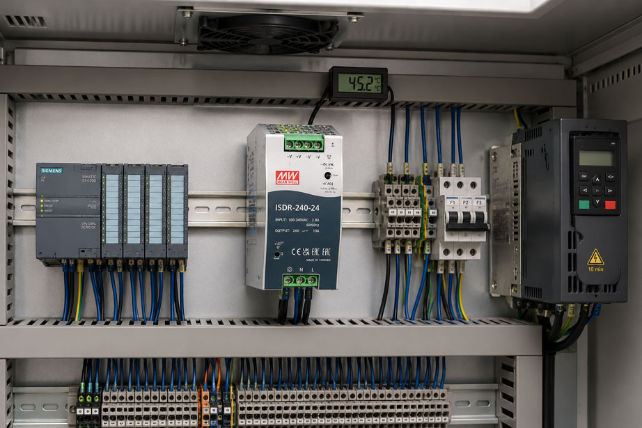
A switching power supply can deliver its rated power without any problems in an air-conditioned test room and still reach its thermal operating limit inside a closed control cabinet during high summer temperatures.
A typical 24 V power supply, for example, may be rated at:
24 V / 10 A = 240 W
.
However, this rated power does not automatically apply at every ambient temperature, mounting position and installation condition. Above a certain temperature, many industrial power supplies may only be operated at a reduced percentage of their rated power.
This is where so-called:
derating
comes into play.
If the temperature around the power supply rises above the range specified for full-load operation, the permissible continuous load decreases according to the derating curve specified by the manufacturer. If this limitation is ignored during control cabinet design, a power supply that appears adequately sized on paper may become thermally overloaded in actual operation.
For a reliable 24 V supply, it is therefore not sufficient to calculate only the required output power. The actual ambient temperature directly at the power supply, the specified mounting position, free convection areas, distances from adjacent heat sources and the total power dissipation inside the control cabinet are equally important.
Suitable devices from the ICS portfolio include, for example, the IDR series – AC/DC power supplies for DIN rail mounting and the more powerful ISDR series. The corresponding technical data explicitly include temperature-dependent derating curves that must be taken into account during system design.
Further solutions can be found under Power Supplies at ICS Schneider and under Measuring Instruments for Control Panel Construction.
Table of Contents
- What does derating mean for a power supply?
- Why must output power be reduced at high temperatures?
- Which ambient temperature is relevant?
- How to read a derating curve correctly
- Practical example with a 24 V DIN rail power supply
- Why mounting position matters
- Ensuring natural convection correctly
- Considering distances to other devices
- Calculating power supply losses
- Considering total control cabinet power dissipation
- How much power reserve is appropriate?
- Distinguishing continuous load from short-term peak load
- Input voltage can also cause derating
- What happens during thermal overload?
- When control cabinet ventilation becomes necessary
- Checking temperature in the finished control cabinet
- Typical design errors
- Practical case: power supply fails only in summer
- Recommended design procedure
- Suitable power supplies from ICS Schneider
- Conclusion
- FAQ
What does derating mean for a power supply?
Derating means that an electrical device may no longer be operated at its full rated power under certain operating conditions.
For a switching power supply, this commonly applies to:
- high ambient temperatures,
- unsuitable mounting positions,
- insufficient convection,
- low input voltages,
- high altitudes above sea level,
- certain combinations of these conditions.
Example
A power supply is rated at:
24 V / 2.5 A
or:
60 W
.
However, the derating curve allows only:
80% load
at the actual ambient temperature.
The permissible continuous output power is therefore only:
60 W × 0.80 = 48 W
and accordingly:
48 W / 24 V = 2.0 A
Under these conditions, the device can therefore no longer be continuously loaded with 2.5 A.
Why must output power be reduced at high temperatures?
A switching power supply does not operate without losses.
Part of the electrical power it consumes is converted into heat inside the device.
Heat is generated, among other things, in:
- power semiconductors,
- transformers and inductors,
- rectifiers,
- capacitors,
- PCB tracks and terminals.
The higher the ambient temperature already is, the smaller the temperature difference between the hot internal components and their surroundings becomes.
This reduces the ability to dissipate heat into the surrounding air.
In simplified terms
A power semiconductor, for example, can be significantly hotter internally than the surrounding air.
If the air temperature around the power supply rises from:
25 °C
to:
55 °C
considerably less thermal reserve remains available.
The manufacturer therefore limits the permissible output power before critical internal component temperatures are reached.
Derating is therefore not merely a precautionary safety margin, but part of the specified operating conditions of the power supply.
Which ambient temperature is relevant?
A particularly common planning error is to assume that the room temperature is the same as the ambient temperature of the power supply.
Example
The temperature in a production hall may be:
30 °C
However, inside a closed control cabinet:
- frequency converters,
- power supplies,
- contactors,
- transformers,
- PLC components,
- signal conditioners
generate additional heat losses.
As a result, the temperature in the upper section of the control cabinet may reach, for example:
48 °C
or more.
For the derating curve, the relevant value is generally the ambient temperature at the device as defined by the manufacturer, not simply the temperature outside the control cabinet.
The upper section of the control cabinet is particularly critical
Warm air rises.
A power supply mounted above:
- a frequency converter,
- a high-power DC/DC converter,
- a transformer
may therefore be exposed to a significantly higher air temperature than an identical device installed further down.
How to read a derating curve correctly
The permissible load is often shown as a graph.
One axis shows:
ambient temperature
and the other:
permissible load in %
Typical characteristic
Up to a certain temperature, the power supply may deliver:
100%
of its rated power.
Above this point, the permissible load decreases.
For example:
| Ambient temperature | Permissible load |
|---|---|
| 40 °C | 100% |
| 45 °C | 100% |
| 50 °C | depending on the specific curve |
| 60 °C | significantly reduced |
These values must not be transferred indiscriminately from one power supply to another. The derating curve of the specific model being used is always decisive.
Practical example with a 24 V DIN rail power supply
For the 24 V version of the IDR-60 series, the rated power is:
60 W
with a rated current of:
2.5 A
The datasheet specifies full-load operation with vertical mounting up to approximately:
45 °C
.
Above this temperature, the permissible load decreases along the derating curve and reaches only approximately:
60%
at:
60 °C
At 60 °C, the full 60 W are therefore no longer available
Instead, only approximately:
60 W × 0.60 = 36 W
At 24 V, this corresponds to:
36 W / 24 V = 1.5 A
A connected continuous load of, for example:
2.2 A
would therefore be too high under these ambient conditions, even though it remains below the 2.5 A rated current stated on the nameplate.
This is exactly why the rated power must always be considered together with the derating curve.
Why mounting position matters
Many DIN rail power supplies are designed for a defined mounting orientation.
With natural convection cooling, the intended arrangement normally allows the heated air to flow:
from bottom to top
through or along the device.
If the power supply is mounted in a different orientation
the internal airflow conditions may change.
Possible consequences include:
- poorer heat dissipation,
- local heat accumulation,
- higher component temperatures,
- additional derating requirements.
The derating curve specified by the manufacturer therefore generally applies only under the defined mounting conditions.
A power supply must not be mounted horizontally or upside down simply because it can mechanically be attached to the DIN rail in that position.
Ensuring natural convection correctly
Many industrial DIN rail power supplies are cooled without a fan.
Heat is dissipated by:
free air convection
Air must be able to circulate
Cool air must be able to reach the device, while heated air must be able to escape upwards.
The following situations can therefore be problematic:
- cable ducts mounted directly above the power supply,
- devices mounted too closely together,
- covers blocking ventilation openings,
- horizontally enclosed assemblies,
- heat accumulation near the top of the control cabinet.
Free installation space is part of the thermal design
A control cabinet can be electrically well designed and still have thermal problems if components are installed too close together without sufficient airflow paths.
Considering distances to other devices
For higher-power DIN rail power supplies, specific minimum or recommended distances may be specified.
For devices in the ISDR series, for example, the following clearances are recommended for continuous full-load operation:
- above: 40 mm,
- below: 20 mm,
- left and right: 5 mm.
If an adjacent device is itself a heat source, a larger lateral distance of:
15 mm
is recommended.
Why the upper clearance is particularly important
The heated air leaves the area around the power supply in an upward direction.
A closed cable duct mounted immediately above the device can obstruct this natural airflow.
Clearance is not wasted control cabinet space
The space required for cooling is functionally part of the device installation.
If planning is based only on:
power supply width in mm
this thermally required installation space can easily be overlooked.
Calculating power supply losses
A power supply with an efficiency below 100% releases heat into the control cabinet.
In simplified form, the power loss can be calculated as:
PV = Pin − Pout
If only the efficiency is known:
η = Pout / Pin
then:
PV = Pout × (1 / η − 1)
Example
The power supply delivers:
Pout = 200 W
with an assumed efficiency of:
η = 92%
The input power is therefore:
200 W / 0.92 ≈ 217.4 W
and the power loss is:
217.4 W − 200 W ≈ 17.4 W
These approximately 17 W are primarily converted into heat inside the control cabinet.
This may not sound like much at first
However, the heat losses from multiple components add up.
For example:
| Component | Example power loss |
|---|---|
| Power supply | 17 W |
| PLC and I/O | 20 W |
| Frequency converter | 60 W |
| Measurement and communication devices | 15 W |
| Other components | 20 W |
This already results in:
132 W power dissipation
inside the enclosure.
Considering total control cabinet power dissipation
The temperature of a power supply is not determined solely by its own power dissipation.
The thermal environment of the entire control cabinet is decisive.
The heat balance includes, among other things
- power supplies,
- PLCs,
- relays and contactors,
- frequency converters,
- servo drives,
- transformers,
- braking resistors,
- measuring instruments,
- communication components.
The total power loss from these devices must be dissipated through:
- the control cabinet surface,
- natural convection,
- filter fans,
- air-to-air heat exchangers,
- control cabinet cooling units.
Also consider the external ambient temperature
A control cabinet that operates without problems at:
20 °C room temperature
does not necessarily do so at:
35 °C hall temperature
.
The design should therefore be based on a realistic worst-case operating condition.
How much power reserve is appropriate?
A blanket statement such as:
always provide 20% reserve
is too simplistic for proper system design.
The required reserve depends, among other things, on:
- maximum continuous load,
- inrush currents of connected loads,
- short-term peak loads,
- ambient temperature,
- derating curve,
- future system expansions,
- required availability.
The available power at the worst operating point is decisive
Assume the connected loads require a maximum of:
180 W
The selected power supply is nominally rated at:
240 W
However, at the specified maximum temperature, the derating curve allows only:
75%
The actually available power is therefore:
240 W × 0.75 = 180 W
This leaves practically no power reserve.
A larger power supply may therefore be required
Not because the connected loads require more than 240 W at room temperature, but because the thermally permissible output power is reduced under real control cabinet conditions.
Distinguishing continuous load from short-term peak load
Some industrial power supplies can provide more than their rated power for a short period of time.
This is useful, for example, for:
- motor starting,
- valves,
- capacitive loads,
- control systems with temporarily high power consumption.
Peak power does not replace sufficient continuous power
A short-term overload capability of, for example:
150% for a few seconds
does not mean that the power supply may be operated continuously above its rated or temperature-reduced output power.
Certain devices in the ISDR series are designed to provide short-term peak power. However, the permissible average or continuous output power remains limited.
Peak capability and thermal derating must therefore be considered separately.
Input voltage can also cause derating
Temperature is not the only factor that can affect the available output power.
For certain power supplies, derating is also required at low input voltages.
Why?
For the same output power, a lower input voltage requires a higher current on the input side.
This can increase the load on components such as:
- rectifiers,
- power semiconductors,
- input filters,
- PCB tracks.
The ISDR documentation therefore also specifies a reduction in output power at low input voltage.
For applications with strongly fluctuating supply voltage, both the temperature derating curve and the input voltage derating curve must therefore be checked.
What happens during thermal overload?
Modern power supplies often provide protection functions against:
- overload,
- short circuit,
- overvoltage,
- overtemperature.
However, a protection function must not be treated as a normal operating mode.
A thermally overloaded power supply may, for example
- reduce its output voltage,
- shut down,
- cycle on and off,
- restart only after cooling down.
The exact behaviour depends on the particular device.
For the machine, the symptoms may look completely different
A PLC may, for example, experience:
24 V → 19 V → restart
and the operator may initially suspect:
- a defective PLC,
- a loose connection,
- a short circuit,
- EMC interference.
In reality, the power supply may simply be operating outside its permissible continuous thermal operating range.
When control cabinet ventilation becomes necessary
If passive heat dissipation from the control cabinet is no longer sufficient, the power loss must be removed in a controlled manner.
Possible measures
- larger control cabinet enclosure,
- improved component arrangement,
- larger spacing,
- filter fans,
- air-to-air heat exchangers,
- control cabinet cooling unit.
Filter fans
They are particularly suitable when the ambient air temperature is sufficiently below the desired internal control cabinet temperature.
Active cooling
If the ambient temperature is already very high, or if the control cabinet must remain closed or protected against dust, an active cooling unit may be required.
Internal air circulation alone is not always sufficient
A recirculation fan distributes heat within the control cabinet.
However, it does not automatically remove heat from the enclosure.
For thermal design, the decisive factor is therefore how the power loss is actually transferred from the control cabinet to the surrounding environment.
Checking temperature in the finished control cabinet
A calculated thermal design should be verified in the finished control cabinet for critical applications.
Useful measuring points include
- air inlet below the power supply,
- the immediate surroundings of the power supply,
- the area above the power supply,
- the upper section of the control cabinet,
- the surroundings of high-power heat sources.
Do not measure only under no-load conditions
A meaningful test should preferably be carried out under:
- typical or maximum system load,
- closed control cabinet conditions,
- realistic ambient temperature,
- sufficient thermal stabilisation time.
A temperature measured immediately after switch-on says little about the later steady-state condition.
Long-term recording may be useful
In systems with varying loads, data logging can reveal whether, for example:
afternoon temperature peaks
coincide with:
24 V supply failures
.
Typical design errors
| Observation | Possible cause | Recommended check |
|---|---|---|
| Power supply operates in the test room but fails inside the control cabinet | higher ambient temperature inside the control cabinet | measure temperature directly at the power supply |
| Failures occur only on hot summer days | derating limit is exceeded | compare maximum temperature with the derating curve |
| Power supply shuts down at high load | temperature-dependent reduction in output power | determine permissible load at the operating point |
| Device becomes unusually hot | insufficient convection | check mounting position and clearances |
| Power supply mounted directly next to a frequency converter | additional heat exposure | increase spacing or change arrangement |
| Cable duct mounted immediately above the power supply | hot air cannot escape adequately | observe manufacturer clearances |
| 240 W power supply feeds a 220 W continuous load but fails at 60 °C | rated power considered without derating | determine permissible output at 60 °C |
| Output voltage fluctuates during mains undervoltage | additional input-voltage derating | check input voltage and datasheet |
| Control cabinet fan is running but temperature remains high | insufficient air exchange or warm ambient air | check airflow and heat dissipation |
| Power supply continuously operates near 100% load | no reserve for temperature or system expansion | prepare a worst-case power balance |
| Power supply mounted sideways | different convection conditions | check permissible mounting orientation |
Practical case: power supply fails only in summer
A machine operates without problems during winter.
During summer, however, sporadic PLC restarts occur.
Installed power supply
24 V / 10 A
Measured continuous load
8.5 A
At first glance, this appears to provide a reserve of:
1.5 A
or:
15%
Temperature measurement
Room temperature:
34 °C
Temperature directly at the power supply:
58 °C
Cause
According to its specific derating curve, the power supply may no longer be operated at full rated power at this temperature.
The nominal reserve therefore no longer exists under real operating conditions.
Additional investigation
A frequency converter is located directly below the power supply.
A closed cable duct runs immediately above it.
This combines several unfavourable factors:
- high hall temperature,
- additional heat source below the device,
- restricted convection above the device,
- high continuous load.
Possible corrective measures
- move the power supply to a thermally more favourable position,
- increase spacing,
- improve control cabinet ventilation,
- use a power supply with a greater thermal power reserve.
The problem was therefore not an insufficient rated power value on the nameplate, but an incorrect assessment of the actually available output power at the real ambient temperature.
Recommended design procedure
- Determine 24 V loads: Calculate the continuous current of all connected loads.
- Determine peak loads: Take inrush currents and temporary additional loads into account.
- Calculate rated power: Combine supply voltage and maximum continuous current.
- Determine maximum ambient temperature: Do not use only the room temperature.
- Consider the position inside the control cabinet: Evaluate heat sources and heat accumulation.
- Check the power supply derating curve: Determine the permissible load at maximum temperature.
- Check mounting position: Follow the manufacturer’s specification.
- Allow sufficient clearances: Provide adequate space above, below and to the sides.
- Consider adjacent heat sources: Increase spacing where required.
- Determine power supply losses: Take efficiency into account.
- Calculate total control cabinet power dissipation: Include all relevant components.
- Evaluate heat dissipation: Size enclosure surface, ventilation or cooling accordingly.
- Check the input voltage range: Consider additional derating at low mains voltage.
- Check the power reserve: Compare available power at the worst operating point.
- Check peak power separately: Do not confuse peak capability with continuous output power.
- Inspect the physical installation: Check airflow paths and cable ducts.
- Measure temperature under load: Thermally verify the finished control cabinet.
- Document the results: Record temperature assumptions, load and power reserve.
Suitable power supplies from ICS Schneider
IDR series – compact DIN rail power supplies
The IDR series includes industrial DIN rail power supplies in the power range of:
15 … 100 W
with a wide AC input range.
The devices are designed for DIN rail mounting and are cooled by free air convection.
IDR-60 with 24 V output
The 24 V version offers:
- 24 V DC output voltage,
- 2.5 A rated current,
- 60 W rated power,
- free air convection,
- mounting on TS-35 DIN rail,
- short-circuit, overload and overvoltage protection.
The derating curve specified in the datasheet is particularly relevant to the topic of this article.
With vertical mounting, 100% load is available up to approximately 45 °C. Above this temperature, the output power must be reduced; at 60 °C, the permissible load is only approximately 60%.
ISDR series – higher power levels for control cabinets
For applications requiring higher output power, the ISDR series is available.
The series includes devices with:
- 88 … 264 VAC input,
- 124 … 370 VDC input,
- power ratings from 75 to 960 W,
- DIN rail mounting,
- free air convection for the corresponding versions,
- overload, overvoltage and overtemperature protection.
Example: ISDR-240-24
The 24 V version provides:
24 V / 10 A = 240 W
and can supply a higher peak power for a short period of time.
The specified operating temperature range extends up to:
+70 °C
but only when the corresponding derating curve is taken into account.
For continuous full-load operation, specific clearances above, below and to the sides of the device are also recommended.
A maximum operating temperature of +70 °C therefore expressly does not mean that full rated power is automatically available at +70 °C.
Further power supplies can be found under Power Supplies at ICS Schneider.
Conclusion
When sizing a control cabinet power supply, it is not sufficient to simply add up the load current and then select a power supply with a slightly higher rated current.
Rated power applies only under defined conditions
If the ambient temperature rises above the full-load operating range of the device, the permissible output power must be reduced according to the derating curve.
The temperature directly at the power supply is decisive
The hall or outdoor temperature can be significantly lower than the air temperature inside a loaded control cabinet.
Mounting position affects cooling
For convection-cooled devices, the airflow specified by the manufacturer must be able to develop freely.
Clearances are part of the device design
Cable ducts and adjacent heat sources must not unnecessarily obstruct heat dissipation.
Power reserve must remain available after derating
The decisive factor is not the nominal reserve at 25 °C, but the remaining reserve at the thermally most unfavourable realistic operating point.
Total control cabinet power dissipation matters
Not only the power supply itself, but all installed devices contribute to heating the control cabinet.
For practical applications
Determine continuous load → identify peak loads → define maximum control cabinet temperature → check the specific derating curve → consider mounting position and clearances → evaluate adjacent heat sources → calculate available output power at the worst operating point → determine total control cabinet power dissipation → size ventilation or cooling → thermally verify the installation under real load.
FAQ: Considering Power Supply Derating in Control Cabinets Correctly
What does derating mean for a power supply?
Derating means that under certain operating conditions, the power supply may only be operated at a reduced percentage of its rated power.
Why must a power supply be derated at high temperature?
As the ambient temperature increases, the power supply becomes less able to dissipate its internal heat losses. The maximum permissible output power is therefore reduced in order to keep internal component temperatures within their specified limits.
Does the rated output power apply up to the maximum operating temperature?
Not automatically. A power supply may, for example, be approved for operation up to +70 °C while providing only a reduced percentage of its rated power at high temperatures.
Where can I find the permissible derating?
The relevant information can be found in the datasheet or derating curve of the specific power supply.
Which temperature should I use for derating?
The relevant value is the ambient temperature at the device as defined by the manufacturer, not simply the room temperature outside the control cabinet.
Can it be significantly hotter inside the control cabinet than in the room?
Yes. Heat losses from the installed components can raise the internal temperature well above the surrounding room temperature.
Why is the upper section of a control cabinet often hotter?
Warm air rises. Heat can therefore accumulate particularly in the upper section of a poorly ventilated enclosure.
Why is the mounting position of a power supply important?
Convection-cooled power supplies are designed for a specific airflow pattern. A different mounting orientation can reduce heat dissipation.
Can I mount a DIN rail power supply horizontally?
Only if the manufacturer allows this mounting orientation. Otherwise, additional derating may be required or the installation may not be permitted.
Why does a power supply need clearance from other devices?
Free space allows the required airflow and prevents adjacent heat sources from additionally heating the power supply.
Can I install a cable duct directly above a power supply?
Only if the specified or recommended clearances are maintained. Insufficient spacing can obstruct natural convection.
How do I calculate the power loss of a power supply?
If the efficiency is known, the approximate formula PV = Pout × (1/η − 1) can be used.
Is a power supply with 95% efficiency loss-free?
No. Even with high efficiency, part of the input power is converted into heat.
What must be considered when calculating control cabinet power dissipation?
The power losses of all installed devices should be taken into account, including power supplies, frequency converters, PLCs, relays, transformers and measuring instruments.
How much reserve should a 24 V power supply have?
A fixed percentage is not appropriate for every application. The required reserve should be derived from maximum continuous load, peak loads, derating, temperature and, where applicable, future system expansions.
Why is a 20% reserve sometimes insufficient?
If the power supply must already be derated by 25% at high temperature, for example, a nominal 20% reserve may disappear completely.
Can an oversized power supply cause problems?
A larger power reserve is generally possible, but efficiency, inrush current, space requirements, costs and behaviour at low loads should also be considered.
What is the difference between continuous power and peak power?
Continuous power may be supplied continuously. Peak power is only permissible for a limited period of time.
Can peak power compensate for temperature derating?
No. Short-term overload capability does not replace sufficient thermally permissible continuous output power.
Can low input voltage also cause derating?
Yes. With certain power supplies, the permissible output power is reduced at low input voltage. The corresponding input-voltage derating curve must therefore also be considered.
What happens if a power supply is thermally overloaded?
Depending on the device, overtemperature protection, current limiting or shutdown may occur. The specific behaviour can be found in the relevant datasheet.
Why does a PLC suddenly restart when it gets hot?
One possible cause is a thermally overloaded 24 V power supply whose output voltage collapses or whose protection function is triggered.
When is a control cabinet fan required?
If passive heat dissipation is insufficient to maintain the required internal temperature, active ventilation or cooling may be necessary.
Does an internal recirculation fan automatically reduce the control cabinet temperature?
Not necessarily. It initially only distributes heat within the enclosure. To reduce the internal temperature, the heat must ultimately be transferred to the surrounding environment.
How can I verify the thermal design in practice?
The temperature should be measured in the closed control cabinet under realistic or maximum load and after sufficient thermal stabilisation.
Which ICS power supply is suitable for smaller 24 V applications?
The IDR series includes compact industrial DIN rail power supplies. The 60 W version is available, among other variants, with 24 V and 2.5 A output.
Which ICS series is suitable for higher power levels?
The ISDR series includes DIN rail power supplies in higher power ranges up to 960 W.
Where can I find further power supplies?
Further devices can be found under Power Supplies at ICS Schneider.