


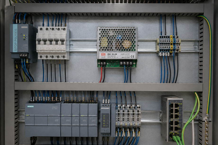
Two circuits can both operate at 24 V DC and still have different ground potentials that can lead to measurement errors, equalizing currents or difficult-to-trace EMC problems when directly connected.
This is exactly where the decision between a galvanically isolated and a non-isolated DC/DC converter becomes technically important.
A non-isolated converter changes the voltage level but still maintains an electrically conductive connection between the input and output sides. For example, input negative and output negative are often directly connected.
A galvanically isolated DC/DC converter, on the other hand, transfers energy between two electrically separated circuits. This allows the output side to establish its own reference potential.
Galvanic isolation is therefore not only a matter of voltage conversion. It determines whether ground potentials are coupled, equalizing currents can flow and interference from one supply circuit can be transferred directly into another circuit.
A suitable example from the ICS portfolio is the ISD series DC/DC converters. The corresponding isolated versions provide galvanic isolation between input and output and are designed with high I/O isolation for industrial DC power supplies.
As a contrasting example, the DC/DC converter model 2218.52 shows that stable voltage conversion is also possible without galvanic isolation. In this device, the input and output sides are galvanically connected.
Further solutions can be found under DC/DC converters and under power supplies at ICS Schneider.
Table of Contents
- What does galvanic isolation mean?
- How does a non-isolated DC/DC converter work?
- How does a galvanically isolated DC/DC converter work?
- Distinguishing 0 V, ground, GND, FE and PE
- How do different ground potentials arise?
- What is a ground loop?
- How do ground potential differences cause measurement errors?
- When is galvanic isolation useful?
- When is a non-isolated converter sufficient?
- Why can 24 V to 24 V conversion also be useful?
- Evaluating isolation voltage correctly
- Does the isolated output have to remain floating?
- Using single-point grounding correctly
- How can galvanic isolation be unintentionally bypassed?
- Galvanic isolation and EMC
- Considering cable shields correctly
- Supplying 4–20 mA measuring circuits correctly
- Remote control cabinets and sensors
- Checking galvanic isolation in practice
- Why a multimeter may still show voltage between isolated grounds
- Practical example: analogue signal jumps when a motor starts
- Typical planning and wiring errors
- Recommended selection procedure
- Suitable DC/DC converters from ICS Schneider
- Conclusion
- FAQ
What does galvanic isolation mean?
Galvanic isolation means that there is no direct electrically conductive connection between two circuits.
In an isolated DC/DC converter, energy and control information are transferred between the input and output sides, for example via:
- transformers,
- magnetic coupling,
- optocouplers or other isolated feedback methods.
This gives the output side its own reference potential.
In simplified terms
In an isolated converter, there is no direct connection between input negative and output negative.
The output side can therefore float electrically relative to the input side or be deliberately referenced to another potential.
In a non-isolated converter
the input and output are electrically connected.
A typical example is:
Vin− = Vout−
This automatically transfers the input reference potential to the output side.
How does a non-isolated DC/DC converter work?
A non-isolated DC/DC converter changes the DC voltage without electrically separating the reference potentials.
Typical circuit topologies include:
- buck converters for reducing voltage,
- boost converters for increasing voltage,
- buck-boost converters for variable input ranges.
A common reference point is normally retained.
Example
A converter reduces:
48 V DC → 12 V DC
If input negative and output negative are connected together:
0 V input = 0 V output
The voltage has changed, but the ground potential has not been isolated.
This is not inherently a disadvantage
If both circuits are intentionally intended to use the same reference potential and no problematic equalizing currents are expected, a non-isolated converter can be:
- simpler,
- more compact,
- more powerful,
- more economical.
A non-isolated converter is therefore not the inferior option. It simply performs a different electrical task.
How does a galvanically isolated DC/DC converter work?
A galvanically isolated DC/DC converter has an electrical isolation barrier between the primary and secondary sides.
The input DC voltage is first switched electronically and then transferred to the secondary side through an isolated transmission stage.
A regulated DC voltage is then generated again on the output side.
This allows, for example
the input side to operate with:
24 V / 0 VA
and the output side with:
24 V / 0 VB
.
The two 0 V potentials do not have to be connected to each other.
This makes it possible to supply a circuit that is to be electrically decoupled from the original supply system.
Distinguishing 0 V, ground, GND, FE and PE
Many wiring problems arise simply because different reference points are generally referred to as “ground” and are then connected together without further consideration.
Several functions should be distinguished technically.
| Designation | Typical function |
|---|---|
| 0 V / GND | electrical reference potential of a DC circuit |
| PE | protective conductor for personal safety |
| FE | functional earth, for example for EMC purposes |
| Housing / chassis | mechanical metal enclosure, connected to PE or FE depending on the design |
| Shield | high-frequency interference dissipation or electromagnetic shielding |
0 V, PE, FE and cable shielding are therefore not automatically the same potential and must not be connected arbitrarily without considering the grounding and EMC concept.
How do different ground potentials arise?
In an ideal circuit, every point along a ground conductor would have exactly the same potential.
In a real industrial installation, however, conductors have:
- ohmic resistance,
- inductance,
- contact resistance.
When current flows through a conductor, a voltage drop therefore occurs.
In simplified form:
U = R × I
Example
The total resistance of the 0 V return conductor between two control cabinet sections is:
0.05 Ω
If a current of:
10 A
flows through it, the resulting potential difference is already:
0.05 Ω × 10 A = 0.5 V
.
For a 24 V solenoid coil, this may be largely insignificant.
For a sensitive measuring signal, however, a potential difference of several hundred millivolts can have a considerable effect.
What is a ground loop?
A ground loop occurs when two points in a circuit are connected to each other through several conductive paths.
Example
Control cabinet A and control cabinet B are connected through:
- a 0 V conductor,
- a cable shield,
- the metallic machine structure or PE connection.
This creates a closed conductive loop.
If even a small potential difference exists between the two points, an equalizing current can flow through this loop.
This current can
- influence measuring signals,
- increase shield currents,
- couple interference into the system,
- cause communication problems.
Large physical loops are particularly critical because they can also pick up electromagnetic interference fields.
How do ground potential differences cause measurement errors?
A measuring instrument normally interprets a voltage difference between its input terminals as the useful signal.
If part of the voltage drop from a ground conductor is added to this signal, a measurement error occurs.
Example with a voltage signal
A sensor outputs:
0 … 10 V
At the same time, there is a potential difference between the sensor ground and the PLC input ground of:
0.4 V
Depending on the wiring, this difference can be added directly to the measured value.
With a 10 V full-scale value, 0.4 V already corresponds to:
4% of the measuring range
.
The actual sensor signal can still be completely correct
The error only arises because of the different reference potentials.
This is precisely why such problems often appear only after installation in a larger system, even though the sensor and control system function perfectly when tested individually.
When is galvanic isolation useful?
A galvanically isolated DC/DC converter is particularly useful when the output side requires a reference potential that is independent of the input.
Typical applications include:
- remote sensors and measuring points,
- multiple control cabinets with different ground potentials,
- battery and vehicle electrical systems,
- sensitive analogue measurement technology,
- measurement and data acquisition systems,
- circuits supplied from electrically noisy sources,
- interruption of unwanted ground loops.
Isolation can also be required at the same voltage
The converter does not necessarily have to convert:
24 V → 12 V
.
An application can also be:
24 V → 24 V galvanically isolated
The main task in this case is not voltage conversion, but potential isolation.
When is a non-isolated converter sufficient?
Galvanic isolation is not required in every circuit.
A non-isolated DC/DC converter can be suitable when:
- the input and output are intentionally intended to use the same 0 V potential,
- all components are located close together,
- no problematic ground loops occur,
- no safety or functional concept requires isolation,
- high output current is required in a compact design.
Example
A stable 12 V supply is to be generated from an existing 48 V vehicle electrical system for additional consumers.
If the entire system intentionally uses a common vehicle ground, a non-isolated DC/DC converter can be technically completely sufficient.
The 2218.52 version, for example, operates with:
48 V DC input → 12 V DC output
at:
10 A
and explicitly has no galvanic isolation between input and output.
Why can 24 V to 24 V conversion also be useful?
At first glance, a DC/DC converter with identical input and output voltage may seem unnecessary.
In an isolated version, however, it performs an additional function.
From:
24 V / 0 V main supply
a separate:
24 V / 0 V isolated supply
can be generated.
Both voltages have the same nominal value, but do not necessarily have the same electrical reference potential.
Typical application
A central 24 V supply powers:
- PLC,
- relays,
- valves,
- contactors.
A sensitive measuring circuit, on the other hand, is to be decoupled from switching interference and ground potential shifts in this supply.
In this case, a galvanically isolated 24 V supply can be useful.
Evaluating isolation voltage correctly
For isolated DC/DC converters, an isolation or test voltage is often specified.
For corresponding ISD versions, for example, an I/O isolation of:
1,500 V AC
is specified.
This value must not be misinterpreted
A test voltage of 1,500 V AC does not automatically mean that a permanent potential difference of 1,500 V between input and output may be applied continuously during normal operation.
The following must also be considered:
- permissible working voltage,
- insulation class,
- clearance and creepage distances,
- applicable safety standards,
- overvoltage category,
- pollution degree.
The isolation test voltage is therefore an important parameter, but does not replace a complete evaluation of the insulation and safety concept.
Does the isolated output have to remain floating?
No. Galvanically isolated and floating are not necessarily the same thing.
After the DC/DC converter, the secondary side can initially float relative to earth.
Depending on the system concept, however, it can deliberately be connected at one defined point to:
- PE,
- FE,
- a local reference potential.
The galvanic isolation from the input side fundamentally remains intact
The output side simply receives a defined reference potential.
However, this connection should be deliberately planned.
Multiple grounding points within the same secondary system can once again create unwanted loops.
Using single-point grounding correctly
In sensitive DC and measurement systems, a clearly defined single-point connection is often used.
For example, the isolated 0 V output can be connected to the system reference at only one designated point.
This makes it possible to control
- where equalizing currents can flow,
- which point serves as the reference,
- how shields and functional earth are integrated.
However, a single-point connection is not a universal EMC rule for every frequency and every system.
For high-frequency interference, short and low-impedance grounding and shielding connections are also important.
How can galvanic isolation be unintentionally bypassed?
An isolated DC/DC converter alone does not guarantee that the overall system remains isolated.
The isolation barrier can be electrically bypassed elsewhere.
Typical examples include
- signal ground between the two circuits,
- USB connection to an earthed PC,
- Ethernet or communication hardware with unsuitable ground coupling,
- 0 V and PE connected on both sides,
- measuring instruments with a common ground connection,
- shield connections that create an additional conductive path.
Example
An isolated DC/DC converter supplies a sensor.
However, the sensor has a voltage output signal of:
0 … 10 V
whose signal ground is connected directly back to the original PLC ground.
The galvanic isolation is therefore bypassed again through the signal line.
For this reason, the complete current and signal path must always be considered during planning, not just the DC/DC converter.
Galvanic isolation and EMC
Galvanic isolation can effectively interrupt DC and low-frequency equalizing currents.
However, it does not represent infinitely high impedance at every frequency.
Real converters have parasitic capacitances
Small capacitive couplings inherently exist between the primary and secondary sides.
High-frequency common-mode interference can therefore partially couple to the output side.
Internal filter components may also be used to meet EMC requirements.
The following therefore remain important
- short cable runs,
- proper shielding,
- separation of power and signal cables,
- suitable filtering,
- correct FE and PE connections.
Galvanic isolation is an important tool within an EMC concept, but it does not replace a complete EMC-compliant system layout.
Considering cable shields correctly
A cable shield is primarily intended for electromagnetic shielding and should not be used unintentionally as an operating-current return conductor.
With an isolated connection, it must therefore be clarified
- where the shield is connected,
- whether it is connected at one or both ends,
- whether high-frequency interference must be discharged,
- whether this creates a conductive connection between the system sections.
The correct implementation depends strongly on:
- signal type,
- frequency range,
- system structure,
- manufacturer specifications.
A blanket rule that every shield must always be connected at only one end is therefore not appropriate for industrial installations.
Supplying 4–20 mA measuring circuits correctly
A 4–20 mA current loop can also be affected by different potentials if several conductive connections exist between the field side and control side.
During planning, it should be clarified
- whether the analogue input is galvanically isolated,
- whether the sensor is supplied from a separate isolated supply,
- whether several channels share a common ground,
- where the shield is connected.
Typical arrangement
An isolated DC/DC supply powers a remote transmitter.
The measuring signal then reaches the control system through a galvanically isolated analogue input.
This allows the field circuit and control-system supply to be consistently decoupled from each other.
Alternative arrangement
If the analogue input itself already provides suitable galvanic isolation, an additional isolated DC/DC converter may not be necessary.
The entire measuring chain should therefore be considered before additional isolation components are installed.
Remote control cabinets and sensors
As the distance between two system sections increases, the probability of relevant potential differences also increases.
Typical causes include:
- long PE conductors,
- high operating currents,
- different supply points,
- lightning and surge protection systems,
- large motors and frequency converters.
Example
A sensor is located 80 metres from the main control cabinet.
The remote machine frame has a slightly different earth potential from the PLC cabinet.
If both systems are connected several times through 0 V, PE and signal wiring, equalizing currents can arise.
A galvanically isolated supply concept can help to cleanly decouple the two ground-potential areas.
Checking galvanic isolation in practice
Whether an unknown DC/DC converter is galvanically isolated should first be checked in the datasheet.
An additional electrical test can provide indications if the device is de-energized and completely disconnected.
With a non-isolated converter
for example, low-resistance continuity may be measurable between:
Vin−
and:
Vout−
.
With an isolated converter
there should be no direct low-resistance connection between the primary and secondary sides.
The specific measurement result can be influenced by:
- internal filters,
- capacitors,
- protective circuitry.
An insulation test using a high test voltage should only be carried out on electronic DC/DC converters if the manufacturer and the specified test procedure explicitly permit it.
Why a multimeter may still show voltage between isolated grounds
A common misunderstanding occurs when a voltage is measured between input and output ground even though the converter is galvanically isolated.
The high input impedance of the multimeter may be the cause
Very small currents can flow through parasitic capacitances inside the converter.
A high-impedance digital multimeter can therefore display an apparent or capacitively coupled voltage.
This voltage can:
- fluctuate,
- collapse when loaded,
- depend on the environment and measuring instrument.
A displayed voltage between two isolated circuits therefore does not automatically prove that a direct galvanic connection exists.
Practical example: analogue signal jumps when a motor starts
A pressure transmitter provides a stable analogue signal during normal plant operation, but shows significant short-term measurement jumps whenever a large frequency-converter-driven motor starts.
Initial situation
The transmitter is located in a remote part of the machine and is supplied from the same main 24 V supply as:
- PLC,
- relays,
- valves.
Sensor 0 V and PLC 0 V are connected by a long cable.
Additional connections exist via:
- cable shield,
- PE,
- machine frame.
Measurement
When the motor starts, a noticeable temporary potential difference can be measured between the local sensor 0 V and the 0 V point in the PLC cabinet.
The transmitter itself operates correctly.
Modification
The field circuit is supplied via a galvanically isolated DC/DC converter and the entire signal wiring is checked with regard to ground and shield connections.
The output circuit receives its own clearly defined reference potential.
Result
The low-frequency equalizing current through the previously common 0 V connection is interrupted and the measuring signal becomes significantly more stable.
The decisive factor was not merely the installation of the DC/DC converter, but the consistent consideration of all conductive connections between the field and control sides.
Typical planning and wiring errors
| Observation | Possible cause | Recommended check |
|---|---|---|
| Measured value changes when large loads are switched | potential shift on common 0 V conductor | measure voltage between local ground points |
| Isolated DC/DC converter does not improve the situation | isolation is bypassed through the signal line | check the complete current and signal path |
| Continuity exists between Vin− and Vout− | non-isolated converter | check datasheet and circuit |
| Voltage is measured between isolated grounds | capacitive coupling and high-impedance measurement | do not automatically interpret this as a galvanic connection |
| Equalizing current flows through cable shield | multiple ground or earth connections | check shielding and grounding concept |
| Analogue signal has a constant offset | different reference potentials | compare ground potentials at both devices |
| Interference occurs only with a long cable | greater potential difference or interference coupling | check local supply and isolation |
| Output of an isolated converter has an undefined potential relative to PE | floating secondary side | check whether defined grounding is required |
| Interference appears after adding a second earth connection | ground loop in the secondary system | identify all grounding points |
| High-frequency interference remains despite isolation | capacitive coupling or unsuitable EMC routing | check filtering, shielding and cable routing |
| 24 V converter selected, but load fails during current peaks | output power too low | check current demand and inrush current |
Recommended selection procedure
- Determine the input voltage: Consider the nominal value and the actual fluctuation range.
- Define the output voltage: Determine the supply voltage required by the load.
- Determine the output current: Take continuous current and load peaks into account.
- Check the potential concept: Do input and output need to use the same 0 V potential?
- Define galvanic isolation: Provide isolation where different potential areas or unwanted ground loops are present.
- Check the entire signal path: Ensure that the isolation is not bypassed through signal ground or communication connections.
- Define the isolation requirement: Do not confuse test voltage with permissible continuous working voltage.
- Define output grounding: Use a floating output or a deliberately defined reference point.
- Distinguish PE and FE: Consider protective and functional requirements separately.
- Define the shielding concept: Consider signal type and EMC requirements.
- Check output ripple: Particularly for sensitive measuring and sensor electronics.
- Consider efficiency: Determine power loss and temperature rise.
- Check the temperature range: Consider derating where necessary.
- Check protection functions: Evaluate short-circuit, overload and overvoltage protection.
- Define the mechanical design: Consider DIN rail, panel mounting or device installation.
- Document the wiring: Clearly identify input and output ground potentials.
- Commission the system: Check ground potentials and output voltage under real operating conditions.
Suitable DC/DC converters from ICS Schneider
ISD series – galvanically isolated DC/DC converters
The ISD series is suitable for applications in which galvanic isolation between input and output is required in addition to voltage conversion.
Depending on the version, input voltages in the range of:
9 … 72 V DC
and output voltages of:
5 … 24 V DC
are available.
Depending on the model, the following features are specified:
- 2:1 wide input range,
- galvanic I/O isolation,
- isolation test voltage up to 1,500 V AC for corresponding models,
- integrated EMI filter,
- protection against short circuit, overload and overvoltage.
Typical application
The ISD series is particularly suitable when an electrically isolated measurement, control or sensor circuit is to be generated from an existing DC supply.
2218 series – voltage conversion without galvanic isolation
The 2218 series represents the alternative design approach.
The devices convert an existing DC voltage into a defined lower output voltage but provide:
no galvanic isolation
between input and output.
Depending on the version, the series includes:
- nominal input voltages of 24 V, 48 V or 60 V DC,
- output voltages of 5 V, 12 V or 24 V DC,
- power ratings from 60 to 240 W.
Example 2218.52
The 2218.52 operates with:
42 … 56 V DC input
and provides:
12 V DC / 10 A
.
The rated power is:
120 W
and the input and output sides are explicitly not galvanically isolated.
This design is therefore suitable for applications in which voltage conversion is required but a common ground potential is desired or uncritical.
Further devices can be found under DC/DC converters at ICS Schneider.
Conclusion
The decision between a galvanically isolated and a non-isolated DC/DC converter should not be based solely on the input and output voltage.
A non-isolated converter changes the voltage level
However, the ground potentials of the input and output remain electrically coupled.
An isolated converter creates a new potential domain
This makes it possible to interrupt unwanted DC and low-frequency equalizing currents between different circuits.
Even 24 V to 24 V can be useful
If the actual purpose is potential isolation, the input and output voltages do not have to be different.
The isolation voltage must be interpreted correctly
A specified test voltage must not automatically be equated with the permissible continuous working voltage between the circuits.
The entire wiring concept is decisive
Galvanic isolation can be unintentionally bypassed through signal grounds, communication lines, cable shields or additional earth connections.
Galvanic isolation does not replace an EMC concept
High-frequency interference can still be coupled through parasitic capacitances. Cable routing, filtering, shielding and grounding therefore remain crucial.
For practical applications
Determine input and output voltage → check power requirements → analyze the grounding and earthing concept → identify possible potential differences → provide galvanic isolation where required → check the entire signal path for unintended conductive bridges → evaluate isolation data → deliberately define output grounding → consider EMC and shielding concept → clearly document the wiring → verify the system under real load and interference conditions.
FAQ: Using Galvanically Isolated DC/DC Converters Correctly
What does galvanically isolated mean for a DC/DC converter?
There is no direct electrically conductive connection between the input and output circuits. Energy is transferred to the output side through an isolated transmission stage.
What is the difference compared with a standard DC/DC converter?
In a non-isolated converter, the input and output normally share a common electrical reference point, such as a common negative terminal.
Is a non-isolated DC/DC converter bad?
No. If a common ground potential is desired and galvanic isolation is not required, a non-isolated converter can be the technically and economically appropriate solution.
Why do you need a galvanically isolated DC/DC converter?
Typical reasons include separating different ground potentials, interrupting unwanted ground loops and decoupling sensitive measurement or control circuits.
What does a common negative terminal mean?
Input negative and output negative are electrically connected and therefore fundamentally share the same reference potential.
What is a ground loop?
A ground loop occurs when two points are connected through several conductive paths, creating a closed current path.
Why are ground loops problematic?
Potential differences can cause equalizing currents that influence measuring signals and create additional interference.
Can ground potentials really be different even though everything is connected to 0 V?
Yes. Real conductors have resistance and inductance. When current flows, voltage drops arise between different 0 V points.
What is the difference between 0 V and PE?
0 V is normally the electrical reference point of a DC circuit. PE is the protective conductor and primarily fulfils a safety function.
What is FE?
FE stands for functional earth and is used for functional or EMC-related purposes, among other things.
Does 0 V always have to be connected to PE?
No. Whether and where such a connection is required depends on the electrical protection, grounding and EMC concept of the system.
Can an isolated output be operated completely floating?
Depending on the device and system concept, yes. However, the output can also deliberately be connected to a defined reference potential.
Is galvanic isolation lost if output negative is connected to PE?
The galvanic isolation between input and output fundamentally remains intact. However, the secondary side is then no longer floating and instead has a defined earth potential.
Why can a second earth connection be problematic?
Multiple connections can once again create a closed current path and therefore a ground loop.
Can a 24 V DC/DC converter convert 24 V to 24 V?
Yes. With an isolated version, the purpose can specifically be to create a galvanically isolated 24 V supply from an existing 24 V supply.
What does I/O isolation of 1,500 V AC mean?
It describes a specified isolation test between input and output. The value must not automatically be interpreted as the permissible permanent working voltage.
Does galvanic isolation block all interference?
No. High-frequency interference in particular can still be transferred through parasitic capacitances or other coupling paths.
Does galvanic isolation help against ground loops?
Yes, if the relevant galvanic connection is actually causing the loop and the isolation point is not bypassed elsewhere.
Can the signal line bypass the galvanic isolation?
Yes. A direct connection between the signal grounds on both sides can bypass the potential isolation created by the DC/DC converter.
Can a USB cable bypass galvanic isolation?
Yes. If the connected device does not have its own galvanic isolation, the ground connection of the USB interface can create an additional conductive path.
Why should the isolation of the analogue input also be checked in a 4–20 mA circuit?
Because the galvanic isolation of the entire measuring circuit depends on which conductive connections exist between the field device and the control system.
How can I tell whether a DC/DC converter is galvanically isolated?
The datasheet provides the most reliable information. Terms such as “I/O isolation”, “galvanic isolation” or “isolated” indicate corresponding isolation.
Can I check the isolation with a multimeter?
A resistance or continuity measurement with the device de-energized can provide an indication. The final assessment should nevertheless be based on the manufacturer’s documentation.
Why does my multimeter still show voltage between two isolated grounds?
High-impedance digital multimeters can display even very small capacitively coupled currents as a voltage. This does not automatically mean that a direct conductive connection exists.
Can I test a DC/DC converter with an insulation tester?
Only if the manufacturer and the specified test procedure explicitly allow it. High test voltages can damage electronic components.
Which ICS converter provides galvanic isolation?
The ISD series includes galvanically isolated DC/DC converters for industrial DC applications.
Which ICS converter is not galvanically isolated?
The 2218 series operates without galvanic isolation between input and output.
Which specific non-isolated 48 V to 12 V version is available?
The 2218.52 operates with a 42 … 56 V DC input and provides 12 V DC at 10 A, or 120 W, without galvanic isolation.
Where can I find additional DC/DC converters?
Further devices can be found under DC/DC converters at ICS Schneider.