


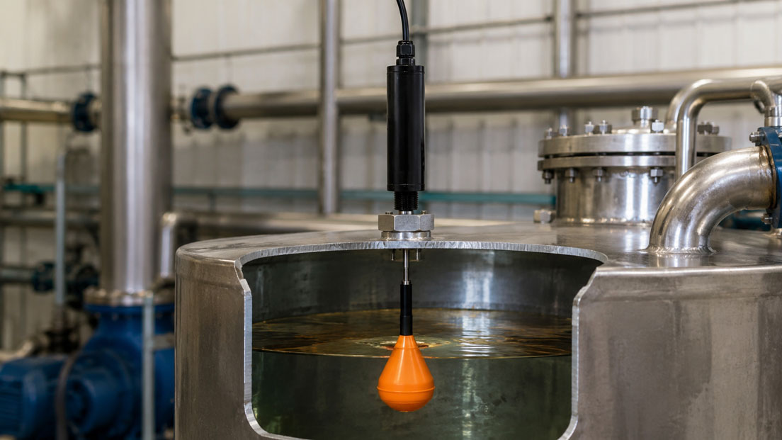
Float switches are among the simplest and most robust solutions for point-level detection in tanks, vessels, pits and process plants. They can indicate a minimum level, protect a pump against dry running or trigger an overfill alarm when the maximum level is reached.
However, their simple operating principle should not obscure the fact that a float switch must be selected and configured carefully. The required switching point does not depend solely on the installation length. The density and viscosity of the medium, float shape, mounting position, switching hysteresis, dead zones and mechanical installation conditions also influence the actual function.
The electrical design is equally important. Reed contacts are often volt-free and require no separate power supply, but they may only be operated within their permissible switching capacity. Otherwise, the contacts may be damaged when directly switching valves, contactors or other inductive loads.
Table of Contents
- Point-level detection instead of continuous level measurement
- How does a float switch work?
- Planning minimum, maximum and multiple switching points
- Switching height, reset point and dead zone
- Influence of medium density on the switching point
- Viscosity, deposits and solids
- Choosing vertical or side mounting
- Selecting vertical float switches correctly
- Installing side-mounted float switches correctly
- Selecting normally open, normally closed or changeover contacts
- Reed contact and electrical connection
- Considering switching capacity and contact protection
- Float switches in hazardous areas
- Materials and media compatibility
- Mechanical installation and cable outlet
- Typical malfunctions and selection errors
- Practical example: Minimum and maximum monitoring of an oil tank
- Information required for selection
- Which products are suitable?
- Conclusion
- Frequently asked questions
Point-level detection instead of continuous level measurement
A float switch does not measure a continuous value across the entire height of a vessel. It merely indicates whether a defined liquid level has been reached or left.
Typical switching tasks include:
- indicating the minimum level,
- protecting a pump against dry running,
- monitoring the maximum level,
- triggering an overfill alarm,
- switching a pump on or off,
- enabling a valve or inlet,
- detecting two levels for two-point control,
- monitoring several alarm and control points in one vessel.
For simple minimum or maximum indication, a float switch is often easier to use than a continuous level sensor. It requires no measuring-range scaling and provides a clear binary signal.
If the current tank contents, a level trend or a continuous control variable must be measured, a continuous level transmitter is generally more suitable. A float switch can then additionally be used as an independent point-level switch.
How does a float switch work?
In a conventional vertical float switch, a float moves along a guide tube with the liquid level. A permanent magnet is located inside the float. One or more reed contacts are installed inside the guide tube.
When the float reaches a reed contact, the magnetic field acts through the non-magnetic wall of the guide tube and actuates the contact. The switching process therefore takes place:
- without contact between the float and the electrical contact,
- without a mechanical feedthrough into the housing,
- without a separate electrical supply for the contact,
- with a volt-free switching signal.
In side-mounted float switches, the float is often attached to a lever. The liquid level moves the lever, whose magnet actuates the reed contact in the stationary switch housing.
In simplified form, the buoyancy force acting on the float is calculated as follows:
FA = ρ × g × Vdisplaced
Here, ρ is the density of the medium, g is gravitational acceleration and Vdisplaced is the volume of liquid displaced by the float. If the density of the medium decreases, the float must become more deeply immersed to generate sufficient buoyancy.
Planning minimum, maximum and multiple switching points
Before selecting the product, the function of each switching point must be defined.
| Switching point | Typical function | Planning consideration |
|---|---|---|
| Low-Low | Dry-running protection or emergency shutdown | Must ensure that sufficient residual medium remains above the pump suction point |
| Low | Switching on a pump or starting refilling | Provide sufficient distance from the Low-Low point to prevent frequent switching |
| High | Switching off a pump or closing the inlet | Consider control hysteresis and process overrun |
| High-High | Independent overfill alarm | Maintain sufficient distance from the maximum permissible filling height |
With multiple switching points, the distances must be selected so that the float can reliably pass each contact. The float also requires sufficient movement space above and below the usable switching range.
A frequent planning error is to position the lowest switching point directly at the end of the guide tube or the highest point immediately below the process connection. At these positions, the float cannot mechanically complete the required magnetic travel.
For pump control, the switch-on and switch-off points should be sufficiently far apart. Too little distance results in frequent switching cycles, increased pump wear and unstable plant operation.
Switching height, reset point and dead zone
For vertical float switches, the specified switching height is generally measured from a defined reference plane on the process connection to the switching point. The applicable reference plane must be taken from the drawing and data sheet.
Three values must be distinguished:
- Nominal switching point: The structurally defined position of the reed contact.
- Actual operating point: The liquid level at which the contact changes state as the level rises or falls.
- Reset point: The position at which the contact switches back when the direction of movement is reversed.
There is a hysteresis between the operating point and the reset point. It is caused by the magnetic-field strength, reed contact and float geometry.
There are also structural dead zones:
- between the process connection and the highest reachable switching point,
- between the lowest switching point and the float stop,
- between multiple contacts if one float operates several switching points.
The ordered switching point must therefore not be derived solely from the total vessel height. The process connection, nozzle length, vessel geometry, float dimensions and required dead zones must also be considered.
Influence of medium density on the switching point
The minimum operating density indicates the lowest density a medium may have for the selected float to rise sufficiently and reliably reach the switching contact.
In a low-density medium, the same float is immersed more deeply than in water. This slightly shifts the actual switching point.
Density assessment is particularly important for:
- light oils,
- diesel and fuels,
- refrigerants,
- solvents,
- liquefied gases,
- hot process liquids,
- media with changing compositions.
The density must be considered at the actual operating temperature. Many liquids have a lower density at elevated temperatures than at room temperature.
If the operating density is only slightly above the stated minimum density, manufacturing tolerances, temperature changes, deposits or additional friction can reduce the operating margin. In this case, a float with a lower minimum operating density or a greater buoyancy volume should be selected.
A general order specification such as “for oil” is therefore insufficient. At least the precise type of oil, minimum density and maximum operating temperature are required.
Viscosity, deposits and solids
Density determines whether the float will rise in principle. Viscosity, by contrast, influences how freely and quickly it can move.
Highly viscous or adhesive media can cause the following problems:
- delayed float movement,
- sticky deposits on the guide tube,
- increased friction between the float and guide tube,
- sticking after prolonged shutdown periods,
- a shifted reset point,
- a blocked lever in side-mounted versions.
Solids, fibres or crystallising components can also obstruct the float. In heavily contaminated wastewater, a freely suspended float switch may be more suitable than a closely guided float on a narrow guide tube.
For adhesive media, the float shape, clearances and cleaning options must be assessed. A larger float with greater buoyancy may be advantageous, but it does not replace an assessment of the tendency to form deposits.
Foam can also be problematic. A float reacts to the buoyancy of the liquid and not reliably to a light foam layer. If a foam boundary must specifically be detected, another measuring principle is often required.
Choosing vertical or side mounting
Float switches are primarily available for vertical or side mounting.
| Design | Advantages | Typical limitations |
|---|---|---|
| Vertical mounting | Multiple switching points possible, precise positioning along the guide tube | Requires installation space above or below the vessel |
| Side mounting | Compact, simple single switching point, also suitable for low vessel heights | Switching point is largely determined by the installation nozzle |
| Suspended float switch | Large movement range, suitable for pits and partially contaminated media | Requires sufficient free space and defined cable or float movement |
| Switch in an external chamber | Switching position can be adjusted externally along the bypass chamber | Requires an additional bypass chamber and process connections |
The mounting position is structurally defined. A float switch designed for vertical mounting must not be installed horizontally without explicit approval.
With certain side-mounted switches, rotating the switch may change the switching function. However, this applies only to models designed for this purpose and must be verified using the installation instructions.
Selecting vertical float switches correctly
Vertical float switches are generally installed in the vessel from above or below. The float moves along a guide tube.
The following information is required for selection:
- position of the sealing or flange face,
- length of the vessel nozzle,
- required switching heights,
- total length of the guide tube,
- number and function of the contacts,
- float dimensions,
- dead zones and stops,
- installation from above or below.
When installed from below, the mechanical direction of movement is reversed compared with installation from above. The electrical switching function must therefore be clearly defined for the actual installation.
The guide tube must not bend due to flow, agitators or mechanical loading. Long versions may require additional guides or supports.
The float must have sufficient clearance from the vessel wall, internal fittings, heating coils and suction pipes. It must not strike or become trapped at any point.
Installing side-mounted float switches correctly
Side-mounted float switches are installed horizontally in the vessel wall using a threaded, flanged or other process connection. The required switching point is largely determined by the height of the connection nozzle.
The following points must be considered during installation:
- specified mounting orientation,
- direction of movement of the float lever,
- free movement area inside the vessel,
- wall thickness and length of the connection nozzle,
- distance from the inlet, agitator and suction point,
- correct position of the cable or housing outlet.
A nozzle that is too long or too narrow may prevent the float from moving fully. The internal geometry of the nozzle, and not only the connection size, must therefore be considered during selection.
Where filling causes turbulence, the switch should not be installed directly in the inlet jet. Otherwise, the float may switch prematurely or erratically.
Selecting normally open, normally closed or changeover contacts
The switching function is normally specified for a defined direction of movement, for example for a rising liquid level.
| Contact function | Behaviour at the switching point | Typical use |
|---|---|---|
| Normally open | The contact closes when the switching point is reached | The alarm or PLC input is activated at the limit level |
| Normally closed | The contact opens when the switching point is reached | Closed-circuit principle and monitored safety functions |
| Changeover contact | One contact opens while a second contact closes | Flexible evaluation or parallel status indication |
The description minimum or maximum switch alone does not define the electrical contact function. A maximum level can be monitored using either a normally open or normally closed contact.
The closed-circuit principle is often preferred for safety-related indications. In this arrangement, the circuit is closed during normal operation. A cable break, power failure or contact opening then also results in a fault indication.
Whether this principle is fully implemented using the selected contact and connected evaluation unit must be shown clearly in the circuit diagram.
Reed contact and electrical connection
A reed contact consists of ferromagnetic contact blades in a hermetically sealed glass tube. The magnetic field of the float moves the contact blades and opens or closes the circuit.
Typical characteristics include:
- volt-free contact,
- no separate power supply required,
- galvanic isolation from the process,
- low mechanical wear,
- suitable for PLC inputs, isolating switch amplifiers or interposing relays.
However, the reed contact does not provide an electronically amplified output signal. The connected circuit must be compatible with the contact rating in terms of voltage, current and load type.
For connection to a PLC, the following must be checked:
- PLC input voltage,
- input current or wetting current,
- contact switching function,
- common reference potential,
- cable-break monitoring,
- required galvanic isolation,
- cable length and interference.
With multiple contacts, it must be clearly documented which conductor belongs to which switching point and contact function.
Considering switching capacity and contact protection
Reed contacts are designed for signal transmission and are not automatically suitable for directly switching larger loads.
Particularly critical loads include:
- solenoid valves,
- contactors and relays with large coils,
- motors and pumps,
- indicator lamps with high inrush currents,
- long cables with high capacitance,
- electronic inputs with large charging capacitors.
Inductive loads generate voltage peaks when switched off. Capacitive loads can produce high current peaks when switched on. Both can damage the contact surfaces or cause the reed contact to weld closed.
For larger loads, the float switch should therefore only control a suitable interposing relay, isolating switch amplifier or PLC input. Depending on the load, a flyback diode, RC network, varistor or another protective circuit may also be required.
The following ratings are always decisive:
- maximum switching voltage,
- maximum switching current,
- maximum switching capacity,
- permissible load type,
- AC or DC operation.
The permissible individual values must not be considered independently. Even if the voltage and current are each below their maximum values, the permissible switching capacity may already be exceeded.
Float switches in hazardous areas
In hazardous areas, the specific float-switch version must be approved for the applicable zone, gas or dust group, temperature class and ambient temperature.
For an intrinsically safe version, the assessment covers the complete circuit:
- float switch,
- cable,
- isolating switch amplifier or Ex barrier,
- PLC input or evaluation unit,
- any other connected equipment.
A standard reed contact must not be used in a hazardous area merely because it is volt-free. Suitable Ex approval and compliance with the electrical limits of the complete circuit are required.
For NAMUR or intrinsically safe circuits, a suitable isolating switch amplifier may additionally be required. Cables, terminals, housings, glands and earthing must comply with the respective explosion-protection concept.
Even for simple float switches, the certificate, nameplate, special conditions and approved ambient temperature must be checked.
Materials and media compatibility
In addition to density and viscosity, the chemical resistance of all wetted parts must be checked.
Depending on the design, these may include:
- the float,
- guide tube or lever,
- process connection,
- seals,
- stop and retaining rings,
- protective tubes or float cages.
Typical materials include stainless steel, various plastics and corrosion-resistant special materials. Suitability depends on:
- chemical composition of the medium,
- concentration,
- process and cleaning temperature,
- pressure,
- possible contaminants,
- cleaning and disinfecting agents.
A stainless-steel version is not automatically suitable for every acid or chloride-containing liquid. Plastic floats may be unsuitable for certain solvents, fuels or high temperatures.
For food, drinking-water or pharmaceutical applications, the required approvals and hygienic materials of the complete version must also be checked.
Mechanical installation and cable outlet
Even a correctly selected float switch can fail if installed improperly.
Important installation points include:
- The float must be able to move freely over its entire travel.
- The specified mounting position must be observed.
- The process connection must not be installed under mechanical stress.
- Do not position the switch directly in the inlet jet.
- Provide sufficient distance from agitators and suction lines.
- Protect the guide tube against bending and mechanical impact.
- Tighten the cable gland according to the cable diameter.
- Close the housing cover and seals correctly.
The cable outlet should be positioned so that water cannot run along the cable into the gland. For outdoor installation, a downward cable loop may be useful as a drip loop.
Where strong vibrations occur, the cable and housing must be mechanically relieved. The connection cable must not support the weight of a suspended float switch unless it is explicitly designed for this purpose.
After installation, the function should be verified by controlled filling or an appropriate mechanical function test.
Typical malfunctions and selection errors
The minimum operating density of the float is too high
The float becomes too deeply immersed in the medium or does not rise reliably. The switching point is not reached or is reached too late.
The density was considered only at room temperature
At a high process temperature, the density of the medium decreases and may fall below the required minimum density.
The switching point is planned without allowing for the dead zone
The float cannot fully pass the contact at the end of the guide tube or immediately below the process connection.
A side-mounted switch is installed in the wrong rotational position
The float moves in the wrong direction or the required switching function is reversed.
The installation nozzle blocks the float
A nozzle that is too long or too narrow limits the movement of the side-mounted float.
The reed contact directly switches a solenoid valve
Inductive voltage peaks overload the contact and cause premature failure or welding.
The switch is installed directly in the inlet
Turbulence and flow forces cause erratic or premature switching.
Deposits on the guide tube are not considered
The float moves slowly, becomes stuck or no longer resets.
The minimum and maximum switching points are too close together
The pump or valve switches too frequently and the process begins to cycle.
The Ex assessment covers only the float switch
The barrier, cable and evaluation unit are not assessed as a complete intrinsically safe circuit.
Practical example: Minimum and maximum monitoring of an oil tank
A storage tank contains a low-viscosity industrial oil. The tank is to be monitored using two switching points:
- minimum level for switching off the transfer pump,
- maximum level for closing the inlet valve.
The process data are:
- medium density at room temperature: 820 kg/m³,
- minimum density at maximum operating temperature: 780 kg/m³,
- medium temperature: +10 to +80 °C,
- unpressurised vessel,
- vertical installation from above,
- switching signal to a 24 V PLC,
- no potentially explosive atmosphere.
The float is selected using the minimum operating density of 780 kg/m³ rather than the density at room temperature. The selected float must have a considerably lower minimum operating density so that sufficient operating margin remains even at the maximum temperature.
The Low switching point is positioned so that the pump suction nozzle remains safely covered. The High switching point is sufficiently below the maximum permissible tank contents to allow for process overrun and the response time of the inlet valve.
Sufficient distance is provided between the two points so that the pump and inlet do not switch continuously in response to small level fluctuations.
The reed contacts are not connected directly to the pump and solenoid valve. They switch two PLC inputs. The actual loads are controlled through suitable PLC outputs and interposing relays.
During commissioning, the tank is filled slowly. The actual operating and reset points are documented and compared with the planned heights. At the same time, it is checked whether the float moves freely back down after the tank is emptied.
Information required for selection
At least the following information is required for reliable float-switch selection:
- switch function: minimum, maximum, pump control or alarm,
- number of switching points,
- position of each switching point relative to a defined sealing face,
- rising or falling liquid level,
- required contact function: normally open, normally closed or changeover,
- precise designation of the medium,
- minimum medium density at operating temperature,
- viscosity and possible deposits,
- solids or fibre content,
- minimum and maximum temperature,
- minimum and maximum process pressure,
- vertical, side-mounted or suspended installation,
- installation from above or below,
- process connection and nozzle dimensions,
- material requirements,
- electrical voltage, current and load type,
- cable outlet, cable length or connection housing,
- degree of protection and ambient conditions,
- Ex, SIL, drinking-water or hygiene requirements.
A meaningful enquiry could read as follows:
Vertical float switch for an unpressurised oil tank, installation from above, minimum medium density 780 kg/m³ at +80 °C, two switching points at 250 and 1,150 mm below the sealing face, both with changeover contacts, stainless-steel version, G 2 process connection, connection housing with cable gland, evaluation via 24 V PLC inputs.
Which products are suitable?
Float switches from WIKA / KSR Kuebler
The float switches category includes various solutions for industrial tanks, process vessels, water and wastewater technology, mechanical engineering and special applications.
Depending on the model, available options include:
- vertical and side-mounted designs,
- one or more switching points,
- normally open, normally closed and changeover contacts,
- stainless-steel and plastic versions,
- different floats for various minimum operating densities,
- cable outlets and connection housings,
- explosion-protected versions,
- customer-specific installation lengths and switching points.
WIKA model FLS for vertical installation
The WIKA model FLS is a vertical float switch for industrial process applications. The float moves along a guide tube and actuates one or more internal reed contacts.
Depending on the version, the FLS offers:
- multiple definable switching points,
- different process connections,
- various float and material versions,
- versions for high process pressures and temperatures,
- explosion-protected versions.
The FLS is particularly suitable when several minimum, maximum or control points are required across a greater vessel height.
WIKA model HLS-M for side mounting
The WIKA model HLS-M is a compact miniature version for horizontal or side mounting.
Typical applications include:
- small tanks and vessels,
- a single minimum or maximum switching point,
- dry-running and overfill protection,
- space-constrained machinery and plant applications.
Because of its compact float, its minimum operating density is higher than that of many larger vertical versions. The medium density must therefore be checked particularly carefully.
WIKA model RLS-4000 for intrinsically safe applications
The WIKA model RLS-4000 is designed for industrial applications with an intrinsically safe circuit. Depending on the configuration, several volt-free reed contacts and additional temperature measurements can be integrated.
It is suitable, for example, for oil, diesel, refrigerant and other liquid applications, provided that the medium, minimum operating density, materials and Ex approval match the measuring point.
WIKA model RLS-6000 for water and wastewater
The WIKA model RLS-6000 is a suspended float switch for water and wastewater applications. Depending on the version, the switching position can be adjusted using the float or switching rod.
The design is particularly suitable for:
- pits,
- collection tanks,
- pumping stations,
- contaminated liquids,
- dry-running and overfill monitoring.
WIKA KSR Kuebler level measurement technology
In addition to float switches, the broader WIKA KSR Kuebler level measurement technology category also includes level indicators, continuous float-based measuring systems, optoelectronic switches and accessories.
If a float switch is unsuitable because of the density, viscosity, deposits or installation situation, an alternative point-level or continuous measuring principle can be selected from this product range.
Conclusion: The switching point does not depend solely on the installation length
A float switch is a robust and practical solution for minimum, maximum, dry-running and overfill indications. However, reliable operation requires complete and careful selection.
The medium density determines how deeply the float is immersed and whether it reliably reaches the contact. The decisive value is the minimum density at the actual operating temperature. Viscosity, deposits and solids additionally influence movement and resetting behaviour.
The switching point, reset point and structural dead zones must be considered separately. With multiple switching points, sufficient distance is required for float travel, process hysteresis and stable pump control.
Vertical, side-mounted and suspended float switches fulfil different installation requirements. The specified mounting position, unrestricted float movement, nozzle geometry and distance from inlets or agitators are decisive.
Electrically, a reed contact may only be operated within its permissible switching capacity. Larger or inductive loads are controlled through a PLC, interposing relay or suitable isolating switch amplifier.
The float switch will operate reliably over the long term only when the medium, density, switching points, mechanical design, electrical connection and, where applicable, explosion protection are considered together.
Frequently asked questions about selecting float switches
How is the switching point of a float switch specified?
For vertical versions, the switching point is generally specified from a defined reference plane on the process connection. The nozzle length, float dimensions and structural dead zones must also be considered.
Why is the density of the medium important?
The float requires sufficient buoyancy. In a low-density medium, it becomes more deeply immersed. This can shift the actual switching point or prevent the contact from being reached if the density is too low.
Can the switching point be adjusted later?
In many vertical float switches, the reed contacts are permanently positioned inside the guide tube and manufactured according to the ordering data. Other designs, such as certain suspended or bypass switches, allow subsequent adjustment. The respective construction is decisive.
Which is better: vertical or side mounting?
Vertical switches allow multiple switching points along a guide tube. Side-mounted switches are compact and particularly suitable for a single defined point level.
Can a reed contact switch a pump directly?
Generally not. Pumps and motors considerably exceed the permissible switching capacity. The reed contact should control a PLC input, interposing relay or suitable switching amplifier.
What happens if the medium is too viscous?
The float may move slowly, become stuck or fail to reset completely. The float shape, clearances, buoyancy and tendency to form deposits must therefore be assessed.
Is a volt-free float switch automatically suitable for hazardous areas?
No. A suitable equipment approval and an assessment of the complete circuit, including the barrier, cable and evaluation unit, are required for hazardous-area use.
Which information does ICS Schneider require for selection?
The required information includes the medium, minimum density, viscosity, temperature, pressure, number and position of switching points, contact function, mounting position, process connection, materials, electrical load, cable outlet and, where applicable, Ex or hygiene requirements.