


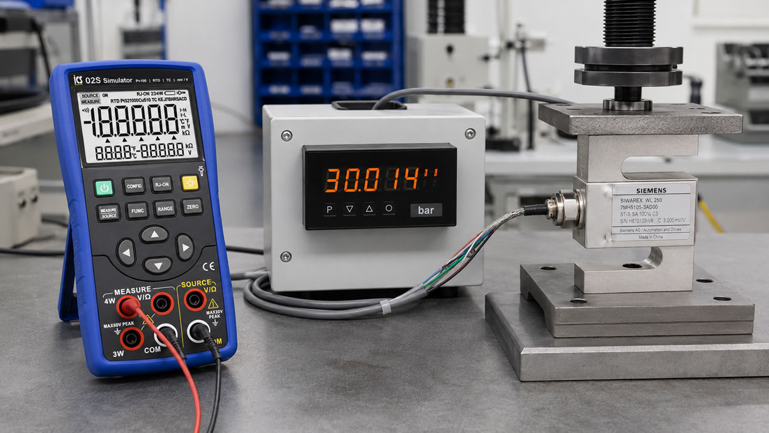
Load cells, force sensors, torque transducers and many melt-pressure sensors do not provide a direct standard signal such as 4–20 mA or 0–10 V. Their output often consists of a very small differential bridge voltage specified in millivolts per volt.
A typical sensor may have a rated sensitivity of 2 mV/V or 3.33 mV/V, for example. The actual output voltage therefore depends not only on the mechanical load but also on the excitation voltage supplied by the measuring amplifier.
By simulating defined mV or mV/V values, measuring amplifiers, digital indicators, weighing modules and PLC scaling can be tested without having to generate an actual force, mass or process pressure. However, a clear distinction must be made between testing only the signal input and simulating the complete strain-gauge bridge, including excitation, bridge resistance and sense lines.
Table of Contents
- What is an mV/V signal?
- How does a strain-gauge measuring bridge work?
- Which sensors provide mV/V signals?
- Calculating the actual output voltage from mV/V
- Distinguishing mV signal injection from true bridge simulation
- Testing with an mV voltage source
- When is a true bridge simulator required?
- Four-wire, six-wire and shield connections
- Testing zero point, span and polarity
- Classifying shunt calibration correctly
- Testing the measuring amplifier, indicator and PLC module
- Shielding and interference
- Testing an mV/V measuring chain systematically
- Practical example: Simulating a 2 mV/V load cell
- What electrical simulation does not test
- Typical errors when simulating mV/V signals
- Selecting a suitable simulator
- Which products are suitable?
- Conclusion
- Frequently asked questions
What is an mV/V signal?
The unit mV/V describes the sensitivity of a bridge-based sensor. It indicates how many millivolts of output voltage the sensor generates at an excitation voltage of one volt and at a defined load.
A rated sensitivity of 2 mV/V means:
- at 1 V excitation, 2 mV is generated at rated load,
- at 5 V excitation, 10 mV is generated at rated load,
- at 10 V excitation, 20 mV is generated at rated load.
The ratio remains unchanged. If the excitation voltage changes, the absolute output voltage changes proportionally.
The unit mV/V must therefore not be treated as a fixed voltage signal. A sensor rated at 2 mV/V does not always provide 2 mV. The actual voltage always depends on the bridge excitation and the current load.
How does a strain-gauge measuring bridge work?
Many force, weighing, torque and pressure sensors use strain gauges. The strain gauges change their electrical resistance when the elastic measuring body deforms slightly under load.
The resistance changes are usually evaluated in a Wheatstone bridge. A full bridge consists of four resistance arms.
The bridge typically has:
- a positive excitation line EX+,
- a negative excitation line EX−,
- a positive signal output SIG+,
- a negative signal output SIG−.
In the unloaded state, the bridge is approximately balanced. Ideally, the voltage between SIG+ and SIG− is close to zero. Under mechanical load, the resistances change, the bridge becomes unbalanced and a differential output voltage is generated.
As this voltage is often only a few millivolts, the measuring chain requires a sensitive differential input with high resolution, stable bridge excitation and suitable amplification.
Which sensors provide mV/V signals?
mV/V signals are used particularly with passive full-bridge strain-gauge sensors.
| Sensor type | Typical application | Special consideration during testing |
|---|---|---|
| Load cell | Tank weighing, platform scales, dosing and conveying systems | Scaling is often in kg or t; several load cells may be connected in parallel |
| Force sensor | Presses, test benches, assembly and joining-force monitoring | Tension and compression directions may have different signal polarities |
| Torque transducer | Test benches, drive technology and friction measurement | Positive and negative torque as well as dynamic signals must be considered |
| Melt-pressure sensor | Extruders, injection-moulding machines and melt pumps | The electronics can be tested without hot process pressure, but the sensor function is not mechanically tested |
| Strain-gauge pressure transducer | Hydraulics, test benches and industrial pressure measurement | Electrical simulation does not replace applying a reference pressure |
Individual strain gauges can also be connected as quarter, half or full bridges. Bridge completion may be required for their simulation and testing. Industrial load cells and force sensors, by contrast, usually already contain a complete measuring bridge.
Calculating the actual output voltage from mV/V
The expected output voltage can be calculated using the following formula:
USignal = S × UExcitation × load fraction
Where:
- USignal: differential output voltage in mV,
- S: rated sensitivity in mV/V,
- UExcitation: actual bridge excitation in V,
- load fraction: load divided by rated load.
Example for a load cell rated at 2 mV/V with 10 V bridge excitation:
| Load | Calculation | Expected signal |
|---|---|---|
| 0 % | 2 mV/V × 10 V × 0 | 0 mV |
| 25 % | 2 mV/V × 10 V × 0.25 | 5 mV |
| 50 % | 2 mV/V × 10 V × 0.50 | 10 mV |
| 75 % | 2 mV/V × 10 V × 0.75 | 15 mV |
| 100 % | 2 mV/V × 10 V × 1.00 | 20 mV |
If the same load cell is excited with only 5 V, the full-scale signal is 10 mV. The excitation voltage configured in the measuring amplifier or actually measured must therefore always be known.
With a rated sensitivity of 3.33 mV/V and an excitation of 10 V, the value at 100 % is:
3.33 mV/V × 10 V = 33.3 mV
An 80 % simulated signal would therefore be 26.64 mV.
Distinguishing mV signal injection from true bridge simulation
In practice, two different test methods are often both referred to as mV/V simulation.
| Test method | Operating principle | Components tested |
|---|---|---|
| Injecting a defined mV voltage | A simulator outputs the previously calculated differential signal voltage | Signal input, amplification, indication, scaling and PLC processing |
| True bridge simulation | A bridge simulator is excited by the evaluation unit and generates a defined ratiometric mV/V ratio | Bridge excitation, signal path, amplification, sense function and, where applicable, sensor monitoring |
Simple mV signal injection is sufficient for many service and troubleshooting tasks. It allows a quick check of whether an amplifier or indicator displays the correct force, weight or pressure value for a defined input.
However, it does not simulate the internal electrical resistance of the load cell or the load on the bridge excitation. Changes in excitation voltage are also not taken into account automatically.
Testing with an mV voltage source
When testing with a precision voltage source, the sensor is disconnected from the evaluation unit. The simulator is then connected to the differential signal inputs.
The simplified connection principle is:
- simulator positive to SIG+ or input +,
- simulator negative to SIG− or input −,
- disconnect the sensor completely from the signal input,
- do not connect EX+ and EX− to the simulator voltage output.
Before connecting the equipment, the wiring diagram of the measuring amplifier and the permissible input and common-mode voltages must be checked. Some evaluation units additionally monitor the sensor resistance or expect a connected bridge. In this case, a simple voltage source may not be sufficient.
The test should normally begin at 0 mV. Several calculated values across the full span are then generated.
A typical sequence of test points is:
- 0 %,
- 25 %,
- 50 %,
- 75 %,
- 100 %,
- then back to 0 %.
For bidirectional force or torque sensors, negative values should also be tested, for example −100 %, −50 %, 0 %, +50 % and +100 %.
When is a true bridge simulator required?
A true bridge simulator is required when not only the voltage input but also the behaviour of a complete strain-gauge transducer is to be simulated.
This is particularly relevant when:
- the evaluation unit itself provides the bridge excitation,
- the excitation voltage must also be assessed during the test,
- remote sense lines are present,
- the input expects a particular bridge impedance,
- sensor breakage or an open circuit is monitored,
- several load cells are connected in parallel,
- high metrological accuracy is required.
The bridge simulator accepts the excitation voltage from the measuring amplifier and uses it to generate the configured mV/V ratio. If the excitation falls from 10 V to 9.8 V, for example, the simulated output signal also falls proportionally.
The simulated bridge resistance must also match the evaluation unit. Common sensor bridges have nominal resistances of 350 Ω, for example, although other values are also used.
Four-wire, six-wire and shield connections
Different connection concepts are used for strain-gauge sensors.
| Connection | Conductors | Function |
|---|---|---|
| Four-wire | EX+, EX−, SIG+, SIG− | Excitation and signal without separate feedback of the excitation voltage |
| Six-wire | EX+, EX−, SIG+, SIG−, SENSE+, SENSE− | Sense lines measure the actual excitation voltage at the sensor and compensate for cable losses |
| Additional shield | Shield or housing connection | Reduces electromagnetic interference and is connected according to the manufacturer’s instructions |
With simple voltage simulation, only the two signal inputs are normally used. Depending on the evaluation unit, however, the sense lines may have to be bridged or connected in another specified manner. The wiring diagram of the relevant amplifier or weighing module is decisive.
Wire colours are not standardised across all manufacturers. EX+, SIG+ or Sense+ must therefore never be identified solely by the cable colour.
Testing zero point, span and polarity
A rated sensitivity of 2 mV/V normally describes the change between the unloaded state and rated load. It does not mean that the sensor outputs exactly 0.000 mV when unloaded.
Real sensors have a zero-signal error or zero offset. The measuring amplifier often compensates for this value using tare, zero adjustment or stored calibration.
The following points should therefore be assessed separately during testing:
- electrical zero point of the input,
- stored tare or zero value,
- amplification or span,
- signal polarity,
- return to zero.
If the evaluation unit displays a negative force value when +10 mV is applied, SIG+ and SIG− may be reversed, or the operating direction may have been inverted in the configuration.
An active tare function can conceal a large electrical offset. Before making a technical assessment, it should therefore be checked whether an old tare or zero adjustment is still active.
Classifying shunt calibration correctly
During shunt calibration, a defined resistor is connected in parallel with one bridge arm. This produces a known imbalance in the strain-gauge bridge corresponding to a specified proportion of the measuring range.
A shunt signal can be used to test the following components:
- strain-gauge bridge,
- sensor cable,
- plug connections,
- measuring amplifier,
- indicator and scaling.
Melt-pressure sensors often have an internal shunt-calibration function. Depending on the sensor series, it may generate a signal close to 80 % of the measuring range, for example. The precise value must be taken from the data sheet, nameplate or calibration documentation of the specific sensor.
However, shunt calibration does not generate any actual mechanical load. It therefore does not test:
- the elastic function of the measuring body,
- the actual force application,
- mechanical damage,
- pressure transmission to the sensor diaphragm,
- hysteresis under actual load,
- mechanical linearity.
It is therefore a functional and plausibility test of the electrical measuring chain, but not a complete substitute for traceable mechanical calibration.
Testing the measuring amplifier, indicator and PLC module
A passive strain-gauge sensor cannot be connected directly to every analogue input without suitable signal conditioning.
A complete measuring chain typically consists of:
Strain-gauge sensor → bridge excitation and measuring amplifier → standard signal or digital value → indicator or PLC
Alternatively, a dedicated weighing or strain-gauge module may already include:
- bridge excitation,
- high-resolution differential input,
- sense connections,
- zero and span calibration,
- filtering and linearisation,
- scaling in kg, N, Nm or bar,
- diagnostic functions.
A conventional 0–10 V analogue input often provides neither the necessary bridge excitation nor the required resolution for signals of only a few millivolts. A separate strain-gauge measuring amplifier is required in this case.
During signal simulation, the complete processing chain should be checked:
- displayed raw value,
- scaled measured value,
- unit,
- decimal point,
- limits and alarms,
- filter time,
- polarity,
- communication with the PLC or control room.
Shielding and interference
mV/V signals have only a very small amplitude. Interference, potential differences and unsuitable wiring can therefore represent a significant proportion of the useful signal.
Particularly problematic sources include:
- motor cables and frequency converters,
- contactors and solenoid valves,
- long unshielded sensor cables,
- shared cable routes with power cables,
- multiple or unsuitable shield earthing,
- poor plug contacts,
- moisture in junction boxes,
- different ground potentials.
The sensor cable should be a twisted, shielded cable in accordance with the manufacturer’s instructions. The shield and sensor housing must be connected in accordance with the plant’s earthing and EMC concept.
If the indicator shows a stable value with the signal input short-circuited but severe fluctuations when the simulator is connected, the measuring leads, connection method, simulator output and reference potential should be checked.
Testing an mV/V measuring chain systematically
- Check the documentation: Determine the rated sensitivity, excitation voltage, bridge resistance, pin assignment and permissible input of the evaluation unit.
- Secure the system: Isolate the measuring circuit safely before disconnecting sensor leads.
- Document the sensor wiring: Record the conductor assignment and terminal connections before disconnecting them.
- Check the excitation voltage: Measure the actual voltage between EX+ and EX−.
- Calculate the simulation values: Determine the required mV values from the mV/V rating, excitation voltage and load fraction.
- Connect the simulator: Connect it only to the designated differential signal inputs.
- Check the zero point: Output 0 mV and check the indication, tare and raw value.
- Carry out a multipoint test: Simulate at least 0, 25, 50, 75 and 100 %.
- Check the return: Reduce the values again and verify the return to zero.
- Test the limits: Check switching points, alarms and PLC logic using targeted intermediate values.
- Document the results: Record the input value, indication, deviation, excitation voltage and configuration.
- Reconnect the sensor: Check the wiring and then carry out an actual functional test.
Practical example: Simulating a 2 mV/V load cell
A tank weighing system has a load cell with the following specifications:
- rated load: 1,000 kg,
- rated sensitivity: 2.000 mV/V,
- bridge excitation: 10.00 V,
- indicator range: 0 to 1,000 kg.
The theoretical output voltage at rated load is:
2.000 mV/V × 10.00 V = 20.00 mV
The following values are set for the multipoint test:
| Simulated signal | Equivalent load | Expected indication |
|---|---|---|
| 0.00 mV | 0 % | 0 kg |
| 5.00 mV | 25 % | 250 kg |
| 10.00 mV | 50 % | 500 kg |
| 15.00 mV | 75 % | 750 kg |
| 20.00 mV | 100 % | 1,000 kg |
At 10.00 mV, the controller displays 625 kg. A check of the PLC configuration shows that a full-scale signal of 16 mV rather than 20 mV had been entered.
After correction, the controller displays plausible values at all simulated points. This initially confirms the signal input, scaling and PLC processing.
The load cell is then reconnected and the vessel is loaded with a known test mass. Only this mechanical test confirms whether the load cell, installation, force application and actual weight measurement are also operating correctly.
What electrical simulation does not test
An mV or mV/V simulation mainly tests the electrical signal path downstream of the sensor.
It can confirm:
- correct amplification,
- correct scaling,
- function of the analogue input,
- indication and unit,
- limits and alarms,
- signal polarity,
- communication path to the PLC.
It does not confirm:
- mechanical sensor accuracy,
- force application and mounting,
- force shunts,
- overload damage,
- load-cell hysteresis and creep,
- pressure transmission of a melt-pressure sensor,
- diaphragm damage,
- actual temperature dependence,
- calibration in the physical measured variable.
A complete calibration therefore additionally requires a known force, mass, torque or traceable reference pressure.
Typical errors when simulating mV/V signals
mV/V is used directly as a millivolt value
For a sensor rated at 2 mV/V, 2 mV is injected even though the amplifier supplies 10 V and expects 20 mV at rated load.
The configured excitation voltage is used instead of the actual value
Cable losses or a different amplifier setting change the sensor’s actual output voltage.
The simulator is connected to EX+ and EX−
The excitation outputs of the amplifier are connected to an external voltage source. This can damage the simulator or evaluation unit.
A standard voltage input is confused with a strain-gauge input
The input provides no bridge excitation or insufficient resolution for signals of only a few millivolts.
Sense lines are not considered
The weighing module reports a sensor fault or controls the excitation voltage incorrectly because the feedback signal is missing.
An active tare function conceals the fault
The zero value appears correct even though there is a large offset or incorrect wiring.
Only the full-scale point is tested
Scaling, linearity or configuration errors at intermediate points remain undetected.
The polarity is not checked
Tension and compression, or positive and negative measuring ranges, are reversed.
Shunt calibration is treated as equivalent to mechanical calibration
The electronics operate correctly even though the measuring body, diaphragm or force application is faulty.
The bridge resistance is not considered
A monitored strain-gauge input does not recognise the simple voltage source as a valid sensor.
Selecting a suitable simulator
At least the following information is required when selecting suitable test equipment:
- simple mV signal injection or true bridge simulation,
- positive, negative or bidirectional signal range,
- rated sensitivity in mV/V,
- bridge excitation in V,
- required resolution and accuracy,
- bridge resistance of the sensor,
- four-wire or six-wire connection,
- DC or carrier-frequency amplifier,
- type of sensor monitoring,
- mobile service use or laboratory application,
- required documentation and calibration.
A precision mV voltage source may be sufficient for a simple test of indication and scaling. If the complete behaviour of a full strain-gauge bridge is to be simulated, a bridge simulator specified for this purpose is required.
Which products are suitable?
Simulators
The simulators category includes test instruments for generating defined electrical and sensor-equivalent signals.
Depending on the instrument, the following signals can be simulated or measured:
- millivolts and DC voltage,
- resistance,
- Pt100 and other RTDs,
- thermocouples,
- 4–20 mA,
- switching states and continuity.
ICS 02S simulator for Pt100, RTD, TC and mV/V
The ICS 02S can measure and generate RTD, thermocouple, mV and voltage signals.
Its key features include:
- measurement and generation of low-voltage signals,
- accuracy down to 0.05 %,
- 5½-digit backlit display,
- four safety sockets,
- measured-value memory,
- automatic zero adjustment,
- battery operation for mobile service tasks.
To test an mV/V evaluation unit, the required millivolt value is first calculated from the rated sensitivity and bridge excitation. This value can then be injected into the signal input of the measuring amplifier or indicator.
Before use, it must be checked whether the evaluation unit accepts a simple differential voltage or expects a complete strain-gauge bridge with defined impedance and sense lines.
Force sensors and force-measuring instruments
The force sensors and force-measuring instruments category includes transducers for tension, compression and alternating forces.
Depending on the version, passive mV/V bridges, integrated measuring amplifiers and 4–20 mA, 0–10 V or digital output signals are available.
Siemens load cells
The Siemens load cells category includes different designs for platform scales, vessels, dosing systems and industrial weighing systems.
The strain-gauge-based load cells provide a load-proportional bridge signal and are evaluated using suitable weighing electronics or strain-gauge input modules.
Dynisco melt-pressure sensors
The Dynisco melt-pressure sensors category includes various sensor series for extrusion, injection moulding and plastics processing.
Depending on the model, mV/V, 4–20 mA and voltage outputs are available. Various mV/V versions also have an internal shunt-calibration function for testing the electrical measuring chain.
IPM5 digital indicator for strain-gauge melt-pressure sensors
The IPM5 digital indicator is designed for evaluating strain-gauge melt-pressure sensors.
It supports automatic sensor recognition for typical sensitivities of 1 mV/V, 2 mV/V and 3.3 mV/V. During commissioning, a defined mV simulation can be used to check the indication, scaling and alarm functions independently of the process pressure.
Conclusion: mV/V must always be considered together with the excitation voltage
An mV/V signal is not a fixed output voltage. The actual millivolt voltage is determined by the sensor’s rated sensitivity, the bridge excitation and the current load fraction.
For a simple functional test of a measuring amplifier, indicator or PLC, a precise mV voltage can be injected. The required values must first be calculated from the mV/V rating and excitation voltage.
A true bridge simulation goes further. It uses the excitation voltage from the evaluation unit and additionally simulates the electrical properties of a strain-gauge bridge and, where applicable, the sense lines.
The zero point, span, intermediate values, return and polarity should always be tested separately. Negative signals should also form part of the test for bidirectional sensors.
Shunt signals are useful for checking the sensor bridge, wiring and amplifier. However, they do not replace mechanical calibration using a known force, mass, torque or reference pressure.
By clearly separating sensor simulation from mechanical testing, it can quickly be determined whether a deviation is caused by the sensor, wiring, measuring amplifier or PLC scaling.
Frequently asked questions about simulating mV/V signals
How many millivolts correspond to 2 mV/V at 10 V excitation?
At rated load, the output is 20 mV. At 50 % of rated load, it is 10 mV, and at 25 % it is 5 mV.
Can I simulate mV/V using a standard voltage source?
For testing the differential signal input, often yes. The required mV value is calculated from the sensitivity and excitation voltage. However, this does not simulate a complete bridge including resistance and sense function.
What is the difference between mV and mV/V?
mV is an absolute voltage. mV/V is a ratio between the output voltage and excitation voltage. If the excitation voltage changes, the absolute mV signal also changes.
Why does an unloaded load cell not output exactly 0 mV?
Manufacturing tolerances, mechanical preloading, installation forces and temperature effects can cause a zero-signal error. This is often compensated for using zero adjustment or a tare function.
Can I connect a load cell directly to a 0–10 V PLC input?
Usually not. The load-cell signal is only a few millivolts and requires stable bridge excitation and a sensitive differential amplifier. A strain-gauge amplifier or dedicated weighing module is required.
What does shunt calibration test?
It creates a defined electrical bridge imbalance and thereby tests the sensor bridge, wiring, measuring amplifier and indicator. No actual force or pressure is generated.
Why does a load cell have six wires instead of four?
In addition to excitation and signal lines, it has two sense lines. These allow the evaluation unit to measure the actual excitation voltage directly at the load cell and compensate for voltage losses in long cables.
Can a melt-pressure sensor be tested completely without process pressure?
The electrical measuring chain can be tested using a simulated mV signal or shunt function. However, the diaphragm, pressure transmission, mechanical accuracy and actual sensor characteristic are not tested completely.
Which information does ICS Schneider require for selection?
The required information includes the sensor type, rated sensitivity in mV/V, excitation voltage, bridge resistance, four-wire or six-wire connection, positive or bidirectional measuring range, required accuracy and whether simple mV signal injection or true bridge simulation is required.