


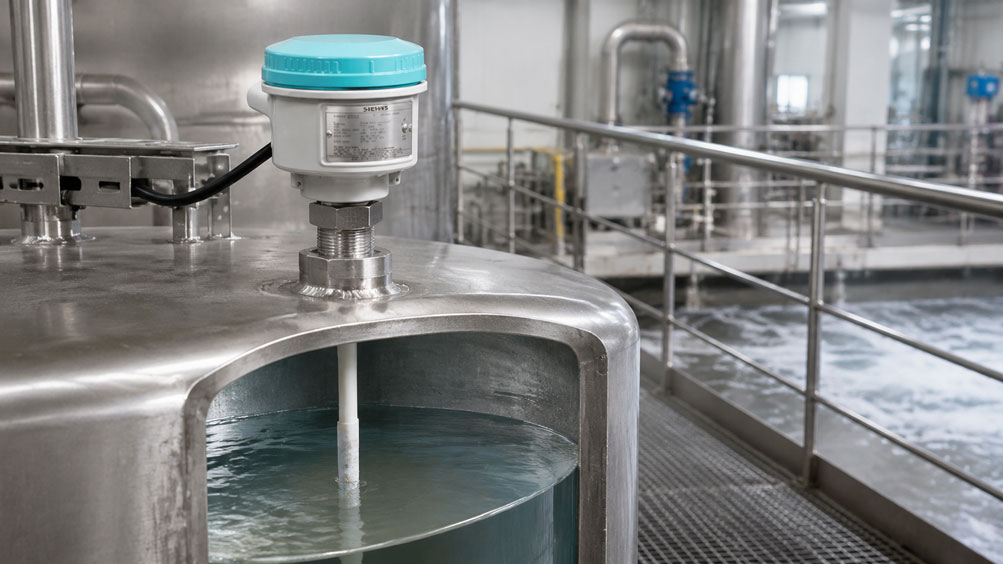
Conductive level switches are a simple and robust solution for detecting water and other electrically conductive liquids. They can be used for overfill protection, dry-run protection, leak detection or two-point control. The measuring principle requires no moving parts and can be adapted to a wide variety of vessels using rod, cable or multiple electrodes.
Reliable operation, however, does not depend solely on whether the medium is generally “conductive”. The lowest expected conductivity, the spacing and wetted length of the electrodes, the vessel geometry, possible build-up and the setting of the controller are all decisive. Foam, condensation, cleaning media and changing product properties can also affect the switching behaviour.
This article explains how to systematically select a conductive point level measurement system, which errors can arise from the vessel earth connection and electrode arrangement, and when another measuring principle is the more reliable choice.
Table of Contents
- How conductive point level detection works
- Electrode, counter-electrode and controller
- Assessing minimum conductivity correctly
- Why alternating voltage is used
- Defining the number of electrodes and switching points
- Electrode spacing and vessel geometry
- Using a metal vessel as the counter-electrode
- Equipping non-conductive vessels correctly
- Build-up, bridging and leakage currents
- Foam, condensation and splashing
- Switching point, sensitivity and delay
- Selecting the electrode material and insulation
- Separating the measuring and safety functions
- Recommended procedure for selection and commissioning
- Common selection and installation errors
- When another measuring principle makes sense
- Suitable level solutions from ICS Schneider
- Conclusion
- FAQ: Conductive level switches
How Conductive Point Level Detection Works
In conductive or conductance-based point level detection, a low electrical measuring voltage is applied between two electrodes. As soon as a conductive liquid wets both electrodes, a small current flows. The controller detects this current and, depending on the operating mode, sensitivity and time delay, switches an output relay or electronic output.
In a metal vessel, the vessel wall can serve as the counter-electrode. One measuring electrode is then often sufficient for a single switching point. In a plastic vessel or coated metal tank, however, a separate earth or reference electrode is required.
The method does not measure the level continuously. The mechanical mounting position or the end of the electrode determines the point level. Several electrodes of different lengths provide multiple switching points, for example minimum, maximum and two-point pump control.
Electrode, Counter-electrode and Controller
A complete measuring point normally consists of three functional groups:
- Measuring electrode: It is wetted by the medium when the required point level is reached.
- Counter-electrode: It provides the return path for the measuring current. This may be a second electrode or the conductive vessel wall.
- Controller: It generates the measuring voltage, evaluates the conductance and provides the switching output.
In separate systems, the electrodes are installed in the vessel and the controller in the control cabinet. Compact level switches combine the electrode and evaluation electronics in one device. The more suitable design depends on the cable length, environment, hazardous area, maintenance access and required diagnostics.
Assessing Minimum Conductivity Correctly
Every controller requires a specific minimum conductance. There is no universal limit for all conductive level switches. Depending on the sensor, cable length, evaluation electronics and electrode geometry, the manufacturer’s specifications can differ considerably.
The selection must not be based on the product’s typical laboratory value, but on the lowest conductivity that can occur in the actual process. The following must be considered:
- the temperature dependence of conductivity,
- dilution by rinsing water or condensate,
- different product formulations and batches,
- fully demineralised, deionised or very pure water,
- cleaning and sterilisation conditions,
- possible mixing with poorly conductive liquids.
The conductivity should be measured under the least favourable operating condition or verified using reliable product data. If it is only just above the device limit, there is no reserve for build-up, temperature changes, cable effects and ageing. A capacitive, optical, mechanical or vibrating method is then usually more robust.
Why Alternating Voltage Is Used
A permanent direct voltage at the electrodes can cause electrochemical reactions. These include polarisation, gas formation, material loss and deposits. These effects change the electrode surface and therefore the measured resistance.
Suitable controllers therefore operate with a low alternating voltage. The periodic polarity reversal reduces electrolysis effects and improves long-term stability. The electrodes must not simply be connected to an arbitrary DC voltage source or directly to a PLC input. The intended controller and its wiring diagram are authoritative.
Defining the Number of Electrodes and Switching Points
The required number of electrodes is determined by the vessel material and the task:
| Task | Metal vessel used as earth | Non-conductive vessel |
|---|---|---|
| One point level | One measuring electrode | One measuring and one reference electrode |
| Two independent point levels | Two measuring electrodes | Two measuring electrodes and one shared reference electrode |
| Pump control between minimum and maximum | Minimum and maximum electrodes | Minimum, maximum and reference electrodes |
With two-point control, the evaluation system retains the switching state between the upper and lower electrodes. This prevents a pump from switching on and off with every small movement of the liquid surface. In this case, the required switching hysteresis is mechanically determined by the height difference between the electrodes.
Electrode Spacing and Vessel Geometry
As the distance between the measuring and counter-electrodes increases, the electrical resistance of the current path rises. At the same time, the wetted electrode surface, liquid geometry and vessel internals influence the measurable conductance. A controller can therefore switch unreliably despite the medium being conductive in principle if the electrodes are very far apart or only minimally wetted.
The reference electrode should reliably reach the relevant level range and provide sufficient contact area. For rod electrodes, the spacing and lengths permitted by the manufacturer must be observed. The electrodes must not touch as a result of flow, an agitator or filling. Flexible cable probes may require weights, spacers or mechanical guides.
Internals, pipe connections and dead zones can cause an electrode to become wetted earlier or later than the main vessel cross-section. The switching point must therefore be related to the actual geometry and not merely to a height shown on a drawing.
Using a Metal Vessel as the Counter-electrode
A metal vessel can serve reliably as the counter-electrode only if a secure, permanently low-resistance electrical connection to the controller exists. Paint, enamel, plastic linings, seals, insulating flange connections or corrosion can interrupt the current path.
The protective conductor connection does not automatically replace the earth connection intended for the measurement. Wiring must be carried out in accordance with the manufacturer’s instructions. Before commissioning, it should be checked whether the vessel wall is actually conductively connected to the measuring earth. If there is any uncertainty, a separate reference electrode is the more controllable solution.
Equipping Non-conductive Vessels Correctly
In plastic, glass or lined vessels, no measuring current can return through the vessel wall. A separate reference electrode is therefore essential. It must be arranged so that it is reliably wetted under all operating conditions in which switching is expected.
For a maximum alarm, a short reference electrode above the normal level is not sufficient. The circuit would then close only when the measuring and reference electrodes are wetted simultaneously. For minimum/maximum control, the shared electrode must normally extend below the lower switching point.
Build-up, Bridging and Leakage Currents
Conductive deposits can create a current path even though the liquid level is below the measuring electrode. Moist, saline or sticky deposits between the electrode and vessel wall or between multiple electrodes are particularly critical.
Possible consequences include:
- delayed reset after the level has fallen,
- a permanently active switching output,
- sporadic switching due to moist leakage paths,
- different behaviour after production and cleaning.
Countermeasures include greater distances in the insulated areas, suitable probe designs, short exposed electrode sections, regular cleaning and a less sensitive setting with sufficient conductivity reserve. If the process permanently forms conductive bridges, a measuring principle that is less susceptible to build-up should be selected.
Foam, Condensation and Splashing
Whether foam triggers a conductive probe depends on the liquid content, bubble size, conductivity and wetting. Wet, conductive foam can simulate a point level; dry foam may not be detected reliably despite its visible height. The switching point should therefore not be located in a foam zone without prior testing.
Condensation on insulators and vessel roofs can cause leakage currents. Splashing or a direct filling jet can wet an electrode temporarily. A suitable mounting position, protection from the inlet and a short switching delay can reduce false switching. However, the delay must not slow a required protective response excessively.
Switching Point, Sensitivity and Delay
The geometric switching point is determined by the position or end of the measuring electrode. The electrical sensitivity specifies the conductance at which the controller identifies the wetted state. It does not move the mechanical switching point arbitrarily, but it affects how partial wetting or build-up is evaluated.
A practical adjustment is made using the actual medium. The electrode is wetted in accordance with the manufacturer’s instructions, and the sensitivity is set with an adequate switching reserve. If the conductivity of the product changes, the setting must be checked.
Switch-on and switch-off delays help with waves, splashes and brief process disturbances. For overfill and dry-run protection, the permissible response time must be determined from the process speed, remaining volume and safety requirements.
Selecting the Electrode Material and Insulation
The electrode is in direct contact with the medium. The material and insulation must therefore be compatible with the chemicals, temperature, pressure and cleaning processes. Stainless steels are commonly used; other metallic materials or coatings may be required for aggressive media.
The following must be checked in particular:
- corrosion resistance of the electrode,
- resistance of the insulator and seal,
- permissible process and ambient temperature,
- process pressure and connection design,
- hygiene requirements and cleanability,
- electrochemical interaction with the vessel and medium.
Corrosion changes not only the service life, but also the surface and contact resistance. For hygienic processes, low-dead-space connections and suitable surfaces are more important than a standard probe that merely functions electrically.
Separating the Measuring and Safety Functions
An operational control system and an independent overfill or dry-run protection system perform different tasks. A shared electrode, controller or PLC logic can create a common cause of failure. For safety-related protective functions, the risk assessment, required Performance Level or SIL, suitable device version, de-energised-to-safe principle and regular functional testing must be taken into account.
An output that indicates the same state for a cable break or power failure as it does for “everything is operating correctly” is unsuitable for many protective tasks. Fail-safe operating mode, line monitoring and relay behaviour must be defined during the design phase and subsequently tested.
Recommended Procedure for Selection and Commissioning
- Define the task: Specify maximum, minimum, leakage or two-point control.
- Check the medium: Assess the minimum conductivity, temperature, build-up and foam.
- Record the vessel data: Check the material, lining, geometry, internals and connection position.
- Confirm the measuring principle: Demonstrate an adequate conductivity reserve above the device limit.
- Define the number of electrodes: Determine the measuring electrodes and any required reference electrode.
- Define the switching points: Derive electrode lengths from the process limits and safety reserve.
- Select the materials: Match the electrode, insulation, seal and process connection to the medium.
- Select the installation location: Consider the inlet, agitator, foam zone, condensation and maintenance access.
- Plan the wiring: Provide the controller, vessel earth, shielding and line monitoring correctly.
- Set the sensitivity: Adjust using the actual medium and the manufacturer’s instructions.
- Set the delay: Filter disturbances without slowing the protective response excessively.
- Perform the function test: Test wetting, reset, line break and power failure.
- Document the states: Record the medium, setting, switching points, delay and test result.
Common Selection and Installation Errors
| Error | Typical consequence | Better approach |
|---|---|---|
| Considering only the typical conductivity | Failure with a cold, diluted or changing medium | Use the lowest actual conductance with a safety margin |
| Assuming a coated metal tank can be used as earth | Measuring circuit remains open | Check the conductive connection or use a reference electrode |
| Positioning the electrodes too far apart | Insufficient measuring current and unreliable switching | Consider the manufacturer’s specifications and actual wetting |
| Applying DC voltage directly to the electrodes | Electrolysis, polarisation and corrosion | Use the specified AC controller |
| Ignoring conductive build-up | Switch remains active despite the level having fallen | Check cleaning, geometry and an alternative principle |
| Automatically treating foam as the liquid level | Non-reproducible switching | Test foam behaviour using the actual medium |
| Reference electrode ends above the minimum point | Minimum switching does not function reliably | Extend the reference electrode below the lowest switching point |
| Setting sensitivity to maximum | Condensation and leakage paths trigger a false alarm | Set only as sensitively as necessary |
| Combining operational and safety switching | A common failure disables both functions | Derive the required independence from the risk assessment |
When Another Measuring Principle Makes Sense
A conductive level switch is unsuitable if the medium does not conduct sufficiently or reproducibly. This applies to many oils, fuels, solvents and very pure water. Heavy conductive build-up or uncertain foam detection also favours a different method.
- Capacitive: For conductive and non-conductive liquids as well as many bulk solids; sensitivity and the influence of build-up must be considered.
- Vibrating: Largely independent of conductivity for many liquids and slurries; depending on the device, robust against foam, bubbles and build-up.
- Optical: Compact and suitable for small vessels; the transparent tip must remain clean.
- Float: Simple mechanical-magnetic principle, independent of conductivity; requires room to move and a sufficient density difference.
Suitable Level Solutions from ICS Schneider
Conductive electrode measuring points are selected for the specific project based on the medium, conductivity, vessel material and switching task. An overview of available point level and level solutions can be found in the level measurement technology category at ICS Schneider.
Pointek CLS100 – Capacitive Alternative for Unsuitable Conductivity
The Pointek CLS100 is a compact capacitive level switch for liquids and bulk solids. It does not use the conductive electrode principle and can therefore be an alternative when the required minimum conductivity cannot be assured.
Pointek CLS200 – Adjustable Capacitive Point Level Detection
The Pointek CLS200 offers adjustable sensitivity and, depending on the application, can be configured so that product build-up has less influence. Suitability must nevertheless be checked with the actual medium and installation conditions.
SITRANS LVL100 – Vibrating Alternative for Liquids and Slurries
The SITRANS LVL100 detects point levels using a vibrating fork. The measuring principle is largely independent of electrical conductivity and is suitable for applications including overfill protection, minimum-level detection and pump protection with liquids and slurries.
Conclusion
A conductive level switch operates reliably when the medium, electrode geometry and evaluation system are considered together. The minimum conductivity must be maintained under the least favourable process conditions with an adequate reserve. Metal vessels may be used as the counter-electrode only when the electrical connection has been verified; plastic and lined vessels require a separate reference electrode.
Electrode spacing, wetted surface and build-up change the measurable conductance. Alternating voltage reduces electrochemical effects, but it cannot eliminate conductive bridges or unsuitable materials. Foam, condensation and splashing must be assessed at the actual measuring point.
For protective functions, fail-safe behaviour, line monitoring, functional testing and the necessary independence from the operational control system must also be defined. If the conductivity or cleanliness of the medium cannot be guaranteed reliably, a capacitive, vibrating, optical or mechanical method is often the better solution.
FAQ: Conductive Level Switches
What minimum conductivity does a conductive level switch require?
The minimum value is device-specific and must be obtained from the controller data sheet. The lowest conductivity occurring in the process, including an appropriate functional reserve, is decisive for the selection.
Can the vessel wall be used as the second electrode?
Yes, if the vessel is metallic, uncoated and permanently connected with low resistance to the intended earth connection. A separate reference electrode is required for plastic, enamel, linings or insulating connections.
Why is alternating voltage used?
The polarity reversal reduces electrolysis, polarisation and electrochemical material loss. The electrodes must therefore be operated with a controller intended for this purpose and not with an arbitrary DC voltage.
How is the switching point defined?
The mechanical switching point is determined by the position or end of the measuring electrode. The controller sensitivity adapts detection to the conductivity of the medium.
What influence does the electrode spacing have?
A greater distance generally increases the resistance of the current path. Reliable switching also depends on the conductivity, wetted electrode surface, geometry and controller sensitivity.
Can a conductive level switch detect distilled water?
Very pure or demineralised water may be below the required minimum conductivity. The actual conductivity must be checked for the relevant temperature and process condition; another measuring principle may be required.
Does foam cause switching?
This cannot be predicted universally. Wet, conductive foam can cause switching, whereas dry or coarse-bubble foam may not. The behaviour should be tested using the actual medium.
Why does the probe not reset after the vessel has been emptied?
Conductive deposits, condensation or liquid films often create a remaining current path. Excessive sensitivity or an incorrectly set switch-off delay may also be the cause.
Can one probe detect two pump switching points?
Yes. Two-point control can be implemented using minimum and maximum electrodes and a shared counter-electrode. The controller must support this function.
What must be considered with long sensor cables?
The permissible cable length, cable type, shielding and separate routing from power cables must be obtained from the manufacturer’s specifications. Cable capacitance and electrical interference can affect sensitive conductance measurement.
Is the method suitable for oil or fuel?
Generally not, because many oils and fuels have poor electrical conductivity. Capacitive, vibrating, optical or float-based level switches are often more suitable.
How is the function tested?
The measuring electrode is wetted with the actual medium beyond the intended switching point and then exposed again. Depending on the device, the cable break, power failure, relay state and fail-safe function must also be tested.