


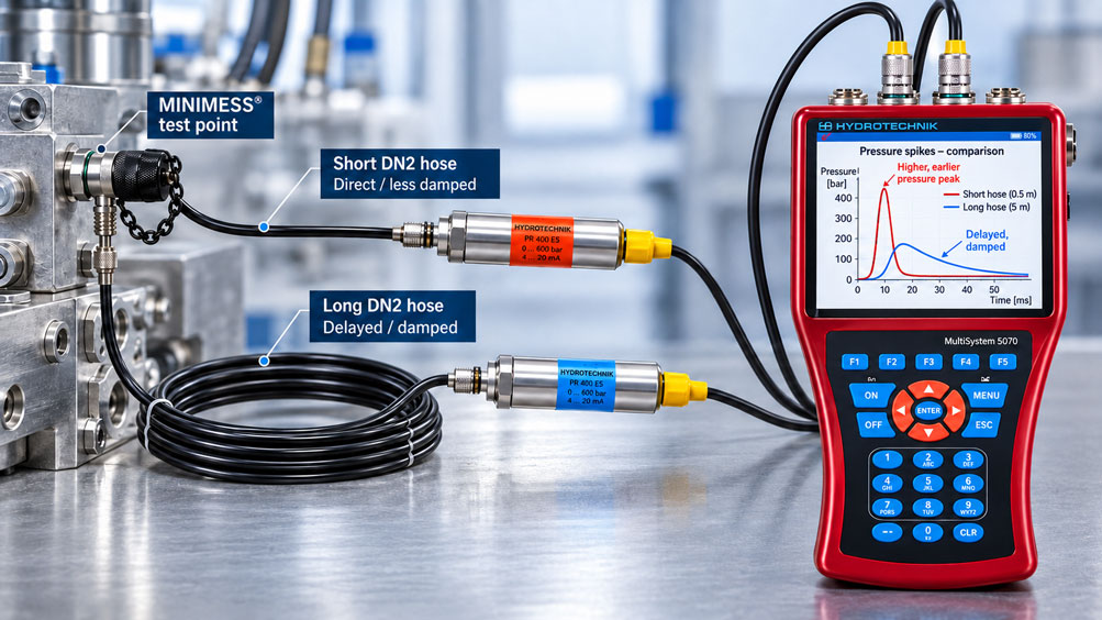
When troubleshooting hydraulic systems, it is often not sufficient to know only the static operating pressure. Very short pressure spikes can occur when valves are switched, cylinders are decelerated, pumps pulsate or loads change rapidly. Such events may last only a few milliseconds and can be significantly higher than the normal operating pressure.
For mobile measurements, a pressure sensor is often connected to the hydraulic system via a MINIMESS test point and a microbore hose. This arrangement is practical: The sensor can be positioned outside an area of the machine that is difficult to access or subject to strong vibration, and the measuring point can be used without extensive modification of the hydraulic system.
However, with fast pressure changes, this convenient measuring arrangement has one important characteristic: The microbore hose does not transmit the pressure signal unchanged from the hydraulic block to the sensor under all conditions.
Hose length, internal diameter, enclosed fluid volume, oil viscosity, hose elasticity, dead volume of adapters and, in particular, trapped air jointly determine the dynamic behavior. In a simplified model, the measuring line can behave like a hydraulic low-pass filter: Slow pressure changes are transmitted almost completely, while fast signal components are attenuated and shifted in time.
For very fast processes, however, this simple low-pass model is no longer sufficient. The fluid has mass, pressure waves require a finite time to propagate, and the complete connection can have natural frequencies. In addition to damping, phase shifts, ringing and resonance effects are therefore possible.
The key point is therefore: In dynamic pressure measurement, a microbore hose is part of the measuring system. It is not only the pressure sensor and data logger that determine which pressure spike is recorded, but also the hydraulic connection between the process and the sensor.
Table of Contents
- 1. Distinguishing process pressure from measured sensor pressure
- 2. Why the microbore hose forms a hydraulic transmission system
- 3. When the measuring line can be simplified as a low-pass filter
- 4. How hose length influences measurement dynamics
- 5. Why DN2 and DN4 respond differently under dynamic conditions
- 6. Why a real hose is not an ideal low-pass filter
- 7. Trapped air as a particularly critical influence
- 8. Taking oil viscosity and temperature into account
- 9. Do not forget couplings, adapters and dead volume
- 10. Selecting pressure sensor, measuring range and bandwidth correctly
- 11. Why a high sampling rate alone is not sufficient
- 12. Practically verifying the dynamic measuring chain
- 13. DN2 and DN4: Correctly interpreting manufacturer data
- 14. Observing pressure, temperature and safety limits
- 15. Selecting the measuring setup according to the measurement objective
- 16. Suitable MINIMESS and measurement technology from ICS Schneider
- 17. Conclusion
- 18. Frequently asked questions about dynamic pressure measurements via microbore hoses
1. Distinguishing process pressure from measured sensor pressure
With direct pressure measurement, the sensor diaphragm is positioned as close as possible to the location where the pressure behavior under investigation occurs. Only small hydraulic volumes are then present between the process and the sensor.
If, on the other hand, the sensor is connected via a microbore hose, there are two different locations: the actual process measuring point and the pressure sensor at the end of the line.
With slowly changing pressure, pressure equilibrium is effectively established after sufficient time. The sensor can then indicate the same static pressure that is present at the MINIMESS test point.
With fast processes, however, this is not automatically the case. A short pressure change must first be transmitted through the fluid column, the hose and all connecting volumes to the sensor diaphragm.
The key distinction for diagnostics is therefore:
pprocess(t) is not identical to psensor(t) under all dynamic conditions.
This does not mean that the pressure sensor is measuring incorrectly. It may measure the pressure actually present at its diaphragm very accurately. However, this pressure may already have been altered relative to the original process signal by the upstream hydraulic measuring line.
2. Why the microbore hose forms a hydraulic transmission system
A dynamic pressure measuring line has several physical properties at the same time.
The fluid in the hose has finite compressibility. Even hydraulic oil is not perfectly incompressible. In addition, a flexible hose wall expands slightly under pressure.
At the same time, the fluid column has mass. If the pressure at the inlet changes very quickly, this fluid must be accelerated or displaced slightly. The small cross-section of the hose generates hydraulic flow resistance.
In simplified terms, three basic properties can be distinguished:
| Hydraulic property | Physical cause | Effect on pressure measurement |
|---|---|---|
| Resistance R | Viscous flow losses in the small cross-section | Damping and delay of fast pressure changes |
| Compliance C | Compressibility of the fluid, hose elasticity, dead volume and air | Storage or accommodation of a small fluid volume during a pressure change |
| Fluid inertance I | Mass of the fluid column | Phase shift, natural frequency and possible oscillatory behavior |
Together, these properties form a hydraulic transmission system.
For slow processes, fluid inertance and wave propagation can often be neglected. In such cases, the low-pass concept is very useful. For fast pressure shocks or pulsating signals, however, the complete dynamic behavior must be considered.
3. When the measuring line can be simplified as a low-pass filter
For idealized laminar flow, the hydraulic resistance of a long, narrow line can be approximated using the Hagen-Poiseuille relationship:
Rhyd = 128 · μ · L / (π · d4)
Where:
- μ = dynamic viscosity of the medium,
- L = line length,
- d = internal diameter.
This equation does not fully describe the dynamic pressure transmission of a real microbore hose. However, it clearly illustrates how strongly hydraulic resistance can depend on the internal diameter.
The enclosed fluid volume is approximately:
V = π · d2 / 4 · L
The hydraulic compliance of the fluid can be approximated from its volume and bulk modulus. In addition, hose elasticity, the volume in the sensor connection and any trapped gas volumes must be taken into account.
In a highly simplified model, the time constant can therefore be interpreted as:
τ ≈ R · C
For an ideal first-order system, the corresponding cutoff frequency would approximately be:
fc ≈ 1 / (2 · π · R · C)
This formula is not a universally applicable manufacturer formula for a real MINIMESS hose. It serves to explain the basic relationship:
The greater the resistance and hydraulic compliance, the more strongly fast signal components can be attenuated.
Slow pressure changes remain below this dynamically critical range and reach the sensor almost completely. Very fast pressure changes, on the other hand, may appear smoothed.
4. How hose length influences measurement dynamics
Increasing hose length changes several parameters simultaneously.
First, hydraulic resistance increases approximately in proportion to the length. At the same time, the enclosed fluid volume increases. With a flexible hose, the total elastically effective hose surface also increases.
The effective mass of the fluid column also becomes greater.
A five-meter microbore hose therefore behaves fundamentally differently under dynamic conditions from a hose of the same design with a length of only 0.5 meters.
For a slow service measurement, this difference does not necessarily present a problem. However, if a valve shock lasting only a few milliseconds is being investigated, hose length can have a considerable influence on the recorded signal shape.
A typical error pattern is:
The steady-state pressure is correct. However, the pressure rise appears slower, the peak appears broader and its maximum amplitude is lower.
For dynamic measurements, the line should therefore generally be kept as short as reasonably possible while still taking safety, temperature, vibration and accessibility into account.
5. Why DN2 and DN4 respond differently under dynamic conditions
When comparing different nominal sizes, it is easy to arrive at an overly simple assumption: “The smaller the hose, the greater the damping.” This statement is incomplete.
A smaller internal diameter does significantly increase hydraulic resistance. At the same time, however, it reduces the enclosed fluid volume.
A larger internal diameter has significantly lower resistance, but contains more fluid and has a larger elastically effective hose surface.
For current standard MINIMESS hoses, the nominal internal diameter is 2.0 mm for DN2 and 4.0 mm for DN4.
It is therefore not possible to derive a universally applicable cutoff frequency from the designation DN2 or DN4 alone.
The following factors are relevant to dynamic transmission at the same time:
- actual hose length,
- internal diameter,
- hose construction,
- wall elasticity,
- medium and viscosity,
- pressure level,
- temperature,
- connection and sensor volume,
- trapped air.
The nominal size should therefore not be considered in isolation.
6. Why a real hose is not an ideal low-pass filter
The low-pass representation is very useful for understanding the basic principle. For very fast processes, however, a pure R-C model is no longer sufficient.
The fluid column has inertia. At the same time, pressure changes propagate as waves through the fluid-hose system.
The complete system can therefore have natural frequencies.
In certain frequency ranges, a measuring line may therefore do more than simply attenuate the signal. Depending on the degree of damping, ringing or resonance amplification may also occur.
For practical applications, this means:
Compared with the actual local process signal, a measured peak can be smaller, shifted in time or, under unfavorable conditions, distorted by the dynamic behavior of the measuring system.
The term “hydraulic low-pass filter” should therefore be understood as an illustrative simplified model and not as a complete description of every dynamic MINIMESS measurement.
The shorter the event being investigated and the higher its relevant frequency components, the more important this distinction becomes.
7. Trapped air as a particularly critical influence
One of the strongest and at the same time most avoidable influences in hydraulic pressure measurement is trapped air.
Compared with gas, hydraulic fluid has low compressibility. An air bubble can therefore significantly increase the hydraulic compliance of a measuring line.
Even a comparatively small gas volume can cause a fast pressure change to be smoothed and delayed much more strongly.
In addition, the size or compression of the gas bubble can depend on the absolute pressure. A measuring setup containing trapped air can therefore exhibit different dynamic behavior at different operating pressures.
Poor reproducibility is particularly problematic. If a hose is completely filled with oil during one measurement and a small air pocket is present during a second measurement, two different hydraulic transmission systems are being compared.
For dynamic comparison measurements, the filling condition of the measuring line should therefore be controlled and reproducible.
A pressurized connection must not be vented by uncontrolled loosening of a fitting. Only the procedures and components specifically intended for pressure relief and venting should be used.
8. Taking oil viscosity and temperature into account
The hydraulic resistance of a microbore line depends directly on the viscosity of the medium.
For many hydraulic oils, viscosity increases considerably as temperature decreases. A measurement immediately after a cold start can therefore exhibit different dynamic behavior from the same measurement with fully warmed-up oil.
The line behaves differently not because its geometry has changed, but because the properties of the medium have changed.
Oil temperature is therefore an important parameter to document for reproducible comparison measurements.
This is particularly important when two measurement series are compared after several hours or under different operating conditions.
Otherwise, an apparent change in system pulsation may in part be caused by a changed transfer function of the measuring line.
9. Do not forget couplings, adapters and dead volume
The hose is not the only hydraulically active element in the measuring chain.
A typical setup may, for example, consist of:
Hydraulic block → MINIMESS test point → mating coupling → microbore hose → adapter → pressure sensor
Each component has its own cross-section and internal volume.
Unnecessarily large cavities directly in front of the sensor diaphragm can be particularly unfavorable for very dynamic measurements. They increase the compressible volume of the measuring chain.
Changes in cross-section can additionally influence dynamic transmission.
For fast measurements, a compact and clearly defined connection chain is therefore advantageous. Several adapters should not be installed in series merely for convenience when a suitable direct connection is available.
In addition, every component must match the rest of the setup with regard to pressure rating, medium, temperature and sealing principle.
10. Selecting pressure sensor, measuring range and bandwidth correctly
An hydraulically optimized connection is of little benefit if the pressure sensor itself is not fast enough.
For dynamic measurements, at least two separate properties of the sensor must therefore be considered:
Measuring range or permissible pressure load and dynamic response behavior.
A sensor with a measuring range of, for example, 0…250 bar is not automatically suitable for a system simply because its normal operating pressure is 220 bar. If pressure spikes significantly above this level can occur during the event under investigation, both measuring range and permissible overload must be taken into account accordingly.
The overload limit must not be regarded as an additional regular measuring range.
For dynamic performance, manufacturer specifications such as response time, bandwidth or natural frequency of the sensor are relevant. Which parameter is specified depends on the respective sensor type.
The usable bandwidth of the complete measurement can never be higher than the bandwidth of the weakest element in the measuring chain.
11. Why a high sampling rate alone is not sufficient
When investigating short pressure spikes, the sampling rate of the measuring instrument is often increased first.
This is fundamentally correct. A short pressure peak can only be recorded if a sufficient number of measured values are acquired during the event.
However, the digital sampling rate describes only the final part of the measuring chain.
The complete transmission path is:
Process → test point → coupling → hose → adapter → pressure sensor → electronics → data logger → software
If a two-millisecond pressure pulse has already been smoothed by the hydraulic measuring line, the original signal no longer reaches the sensor.
A data logger may then measure at 1 kHz, 10 kHz or an even higher sampling rate – it merely records the already hydraulically modified sensor signal more precisely.
A higher sampling rate applied later cannot reconstruct a pressure peak that has already been physically attenuated.
The MultiSystem 5070, for example, enables fast multi-channel measurements and is therefore well suited to analyzing time-dependent hydraulic quantities. However, the sensor and hydraulic connection must also be suitable for the dynamics being investigated.
12. Practically verifying the dynamic measuring chain
In many service applications, the exact mathematical transfer function of an existing hose setup is unknown. In such cases, comparison measurement is a very informative method.
Assume that a machine is suspected of generating a pressure spike when a valve closes quickly.
The first measurement is carried out using an existing long DN2 service hose. The recording shows a relatively broad and moderate peak.
The same measurement is then repeated – under identical or at least highly reproducible process conditions – using a significantly shorter hydraulic connection.
If the pressure rise is now steeper and the maximum peak is higher, this is a strong indication that the original measuring line influenced the dynamics.
An even more informative method is synchronous two-channel measurement. A fast sensor is connected as close to the process as possible, while a second sensor is operated through the microbore line under investigation.
The two signals can then be compared with regard to:
- peak amplitude,
- rise time,
- time delay,
- signal width,
- ringing.
This reveals the actual transmission effect of the specific measuring setup without relying solely on a theoretical hose model.
13. DN2 and DN4: Correctly interpreting manufacturer data
When selecting a MINIMESS microbore hose, the specifications for static or general measurement applications must be distinguished from the conditions specified for dynamic applications.
For current standard MINIMESS hoses, Hydrotechnik specifies, among other things, the following mechanical key data:
| Version | Internal / external diameter | Max. operating pressure for measurement applications | Max. operating pressure for dynamic applications | Permissible rate of pressure rise |
|---|---|---|---|---|
| DN2-400 | 2.0 / 4.9 mm | 400 bar | 300 bar | 3,900 bar/s |
| DN2-630 | 2.0 / 4.9 mm | 630 bar | 500 bar | 6,300 bar/s |
| DN4-315 | 4.0 / 8.0 mm | 315 bar | 240 bar | 3,120 bar/s |
| DN4-450 | 4.0 / 8.0 mm | 450 bar | 340 bar | 4,420 bar/s |
For these standard versions, the manufacturer also specifies an operating temperature range of −20 °C to +100 °C and briefly up to +120 °C. The minimum bend radius is 20 mm for DN2 and 40 mm for DN4.
These specifications are important for mechanical selection. However, they do not automatically describe the metrological bandwidth of a specific hose-sensor combination.
Another particularly important manufacturer note is that the maximum permissible operating pressure of a complete hose assembly is always determined by the individual component with the lowest permissible pressure limit.
A DN2-630 hose assembly therefore does not automatically turn a connected sensor, adapter or test point with a lower pressure rating into a 630-bar measuring chain.
14. Observing pressure, temperature and safety limits
When investigating pressure spikes, one particular challenge is that the maximum pressure being sought may not yet be known.
The measuring chain must therefore be designed with an adequate safety margin for the realistically expected dynamic load.
In addition to the microbore hose, the following components must be checked:
- MINIMESS test point,
- mating coupling,
- hose fittings,
- adapters,
- pressure sensor,
- seals.
The MINIMESS 1620 series is available in suitable versions for operating pressures up to 630 bar. However, the actual limit of an assembled measuring chain may be significantly lower because of other components.
The sealing materials must also be compatible with the medium and temperature. Depending on the version, different sealing materials are available for MINIMESS test points.
Before measurement, the hose assembly should be inspected for cracks, blisters, abrasion, kinks, damaged fittings and suspicious sealing points.
A damaged microbore hose must not continue to be used merely because it initially appears leak-tight during a static test.
15. Selecting the measuring setup according to the measurement objective
There is no single optimum hose configuration for every hydraulic measurement.
| Measurement task | Recommended approach |
|---|---|
| Static operating pressure | MINIMESS microbore hose with a practical length |
| Slow load changes | Defined DN2 or DN4 setup; document hose configuration |
| Mobile service measurement | MINIMESS test point, suitable hose and appropriate pressure sensor |
| Short valve shocks | Keep the hydraulic connection as short and air-free as possible |
| Pump pulsations | Consider hose transmission and sensor bandwidth together |
| Very short pressure spikes | Position the sensor as close as possible to the process measuring point |
| Unknown hose influence | Compare with a shorter line or the most direct measurement possible |
| Analysis of hose influence | Synchronous two-channel measurement before and after the measuring line |
The correct setup therefore depends directly on the measurement objective.
A long service hose may be very suitable for routine pressure monitoring while at the same time being unsuitable for accurately analyzing an extremely short valve shock.
Conversely, direct sensor mounting is not appropriate in every machine. High vibration, high fluid temperatures, mechanical collision risk or poor accessibility may make it preferable to decouple the sensor from the process using a measuring line.
The objective is therefore not generally to “avoid hoses”, but to design the hydraulic connection to match the required measurement dynamics.
16. Suitable MINIMESS and measurement technology from ICS Schneider
ICS Schneider Messtechnik offers components and systems for temporary and permanent hydraulic measurements. An overview can be found under MINIMESS Couplings and Hoses.
MINIMESS microbore hoses
Under MINIMESS Hoses, various DN2 and DN4 versions are available for measurement, service and diagnostic applications.
For dynamic measurements, hose version and length should not be selected solely on the basis of mechanical accessibility. Required measurement dynamics, pressure, medium and temperature must all be considered together.
MINIMESS 1620
The MINIMESS 1620 is a mechanically actuated test point with an M16×2 coupling thread. It provides compact system access for pressure measurements and other diagnostic tasks on fluid systems.
The series is widely used and is available in suitable versions for operating pressures up to 630 bar.
MultiSystem 5070
For recording fast hydraulic processes, the MultiSystem 5070 is one of the available solutions.
The mobile multi-channel measuring system enables sampling rates of up to 10 kHz in dynamic operation and can record several hydraulic measured variables simultaneously over time.
A high recording rate does not, however, replace the required hydraulic and sensor bandwidth. When investigating very fast pressure spikes, the test point, hose, adapter, pressure sensor and measuring instrument must be considered as one complete measuring chain.
Further technical articles
If an existing measuring point responds too slowly in general, we cover the typical causes in detail in the article “Pressure Measurement via Microbore Hose Responds Too Slowly: Check Volume, Air Bubbles and Throttling Effect”.
The mechanical load caused by recurring pressure cycles and the safe selection of MINIMESS components are discussed in the article “MINIMESS on Pulsating Hydraulic Lines: Correctly Evaluating Pressure Cycles, Wear and Safe Measurement”.
For the selection of sensor, adapter and measuring range, the article “Connecting a Temporary Pressure Sensor to MINIMESS: Safely Planning Measuring Range, Adapter and Cable” is also relevant.
17. Conclusion
A MINIMESS microbore hose is a very practical connection between an existing hydraulic measuring point and a pressure sensor. For static and slowly changing pressures, this connection can be largely uncritical from a measurement perspective.
For short pressure spikes, however, the situation changes.
The measuring line has hydraulic resistance, a compressible fluid volume, an elastic hose wall and a fluid mass. This creates its own hydraulic transfer function.
In a simplified model, the combination of resistance and compliance acts like a low-pass filter. Hose length, internal diameter, viscosity and air content then help determine how strongly fast pressure changes are attenuated.
A real microbore hose, however, is not an ideal first-order low-pass filter. At higher frequencies, fluid inertance and wave propagation become relevant. This can additionally result in phase shifts, natural frequencies and resonance effects.
The statement “DN2 attenuates more strongly than DN4” is therefore just as oversimplified as the statement “a 10 kHz data logger automatically measures every 10 kHz pressure spike correctly”.
For reliable dynamic measurements, the complete chain must be considered:
Process → MINIMESS test point → coupling → hose → adapter → pressure sensor → measuring instrument.
Particularly important are a hydraulic connection that is as short and clearly defined as possible, a reproducible air-free filling condition, a suitable pressure sensor and sufficiently fast data acquisition.
If the dynamic effect of an existing measuring line is unknown, a comparison measurement with a shorter connection or a synchronous two-channel measurement often provides the clearest answer.
The microbore hose should therefore not be regarded as an insignificant “extension hose”, but as a deliberately designed part of the dynamic pressure measuring chain.
18. Frequently asked questions about dynamic pressure measurements via microbore hoses
Does a MINIMESS microbore hose act like a low-pass filter?
In a simplified model, the combination of hydraulic resistance and compliance can indeed behave like a low-pass filter. Slow pressure changes are transmitted almost completely, while fast changes can be attenuated or delayed. For very fast processes, however, this simple model is not sufficient because fluid inertance, wave propagation and resonances may also become relevant.
Why does a long hose attenuate pressure spikes more strongly?
As hose length increases, hydraulic resistance, fluid volume, effective fluid mass and the influence of hose elasticity all increase. This changes the dynamic transfer function.
Is DN2 unsuitable for fast pressure measurements?
No. DN2 is frequently used for hydraulic pressure measurements and has a very small enclosed fluid volume. For very fast processes, however, hose length, fluid, hose construction and the rest of the connection chain must be considered.
Is DN4 automatically faster than DN2?
Not necessarily. DN4 has a larger free cross-section and therefore significantly lower hydraulic resistance, but at the same time it also has a larger fluid volume. The actual dynamic behavior depends on the entire measuring system and cannot be derived from nominal size alone.
Why does the internal diameter have such a large influence?
In the simplified laminar pipe-flow model, hydraulic resistance is inversely proportional to the fourth power of the internal diameter. Small changes in diameter can therefore significantly alter the resistance. For complete dynamic pressure transmission, however, additional effects must also be considered.
Why are air bubbles so problematic?
Air is much more compressible than hydraulic fluid. A trapped gas volume therefore increases the hydraulic compliance of the measuring line and can delay or attenuate short pressure changes much more strongly.
Can a long hose also produce a peak that is too high?
The simple low-pass model would primarily predict attenuation. However, a real pressure transmission system also has fluid inertance and natural frequencies. Under unfavorable dynamic conditions, resonance and ringing can therefore occur. For this reason, an unknown measuring line should not be treated exclusively as an ideal low-pass filter.
Can a higher sampling rate make an attenuated peak visible again?
No. A higher sampling rate only improves the time resolution of the signal actually present at the pressure sensor. If the original pressure spike has already been hydraulically attenuated, it cannot be restored by increasing the digital sampling rate.
How fast should the data logger be?
The required sampling rate depends on the shortest or highest relevant dynamics of the pressure signal under investigation and on the sensor bandwidth. The sampling rate should be significantly higher than the measurement bandwidth actually required. At the same time, the hydraulic connection must be capable of transmitting this bandwidth to the sensor in the first place.
How can I determine whether my hose is distorting the pressure peak?
A practical method is to compare the measurement with a significantly shorter measuring line or, where technically possible and safe, with a sensor installed as close to the process as possible. A synchronous two-channel measurement using one process-near sensor and a second sensor behind the hose under investigation is particularly informative.
Why should the oil temperature be documented?
The viscosity of hydraulic oil depends on temperature. With cold and therefore more viscous oil, the hydraulic resistance of a microbore line may be higher than with oil at normal operating temperature. This can also change the dynamic transmission behavior.
What internal diameters do standard MINIMESS hoses have?
For current standard Hydrotechnik versions, DN2 has an internal diameter of 2.0 mm and DN4 an internal diameter of 4.0 mm. The specific hose version should nevertheless always be checked against the relevant data sheet.
Is the static operating pressure also the permissible dynamic pressure?
Not necessarily. For current standard MINIMESS hoses, Hydrotechnik distinguishes between the maximum operating pressure for measurement applications and a lower maximum operating pressure for defined dynamic applications. For pulsating or highly dynamic measurements, the corresponding manufacturer data for the specific hose version must therefore be used.
Which pressure limit applies to a complete MINIMESS measuring chain?
The permissible limit is determined by the weakest component involved. Test point, mating coupling, hose, fitting, adapter and pressure sensor must therefore be evaluated together.
What information does ICS Schneider require to configure a dynamic measuring chain?
Useful information includes the MINIMESS series or existing test point, medium, operating pressure, expected maximum pressure peak, pressure rise or event duration, medium and ambient temperature, required hose length, available installation conditions, required measurement duration, desired number of measuring channels and the approximate dynamics of the event to be investigated.