


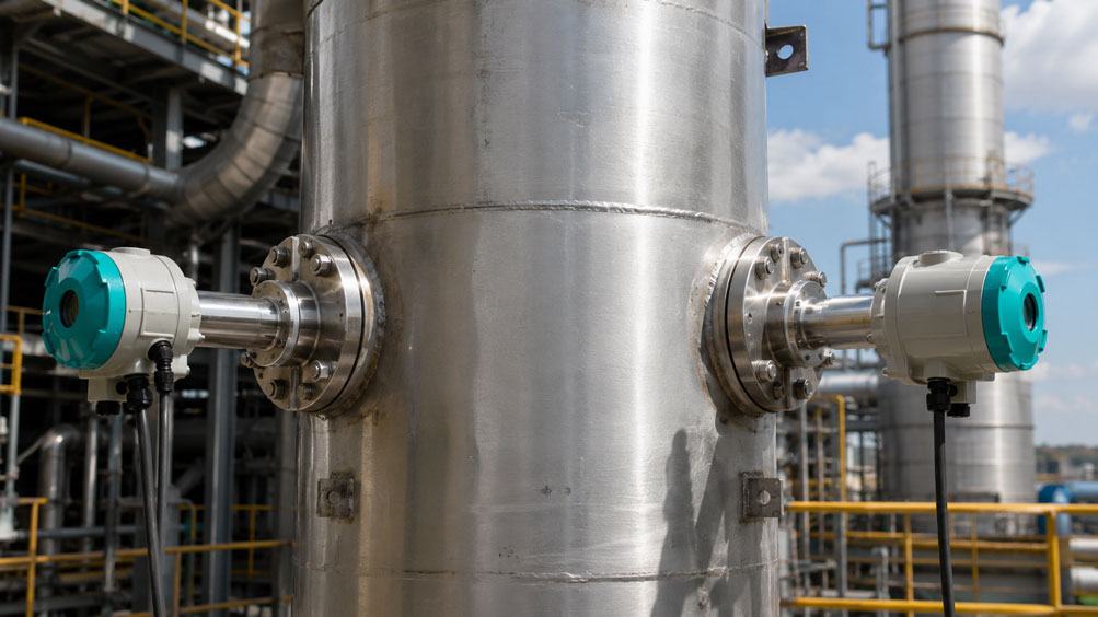
An in-situ laser gas analyzer is installed directly on a flue gas or process duct.
Transmitter and receiver are positioned opposite each other.
The analyzer initially operates stably.
After several weeks, however, the optical transmission decreases.
The measured-value display becomes more unstable and eventually the instrument reports poor signal quality.
Is the process gas the cause?
Possibly – but other possible causes include:
- a shifted optical axis,
- contaminated optical surfaces,
- insufficient purge gas,
- dust deposits in front of the purge tubes,
- an incorrectly considered optical path length,
- thermally distorted or displaced process flanges.
In an in-situ laser gas analyzer, mechanical installation, optical alignment and purging are integral parts of the measurement chain.
Unlike extractive gas analysis, the sample gas is not extracted and conditioned.
The measurement is performed directly through the process gas:
Transmitter → Process gas → Receiver
All conditions within this optical path therefore directly influence the available light intensity and thus the quality of the measurement.
The most important relationships are:
optical axis → light must reliably reach the receiver
dust → attenuates and scatters the laser radiation
purge gas → protects the optics and influences the effective measuring path
path length → influences absorption and detection limit
temperature + pressure → influence spectroscopic evaluation
Poor transmission should therefore not simply be “smoothed out” by increasing the time constant or changing the scaling. The first step is to determine why the optical signal has deteriorated.
Suitable in-situ systems can be found at ICS Schneider under Continuous In-Situ Process Gas Analysis and under Siemens Process Instrumentation.
Table of Contents
- How does an in-situ laser gas analyzer work?
- What does a diode laser analyzer actually measure?
- Transmitter and receiver as an optical measuring path
- Why optical alignment is critical
- Preparing process flanges correctly
- Considering thermal movement of the measuring point
- Determining the effective optical path length correctly
- Why path length influences the measured value
- How dust influences the measurement
- Considering particle size and path length together
- Why the optics are purged
- Selecting the correct purge gas
- Special considerations for O₂ measurements
- Setting the purge flow correctly
- How purge gas changes the effective measuring path
- Detecting contaminated windows and optics
- Using transmission as a diagnostic parameter
- Systematically investigating poor signal quality
- Considering process temperature
- Considering process pressure
- Avoiding condensation
- Selecting a suitable installation location
- Systematically commissioning the analyzer
- Maintenance based on signal condition rather than calendar alone
- Typical error patterns
- Practical example: O₂ measurement in a flue gas duct
- Suitable ICS products
- Conclusion
- FAQ
How does an in-situ laser gas analyzer work?
In in-situ gas analysis, the gas concentration is measured directly in the process.
A typical cross-duct arrangement consists of:
Transmitter → Process duct → Receiver
No conventional sample gas transport
With an extractive analyzer, by contrast, the following arrangement is used:
Process gas → Sampling → Line → Conditioning → Analyzer
Advantage of in-situ measurement
The measured value is available without the delay caused by a long sample gas line or gas conditioning system.
At the same time, the process itself becomes part of the optical system
Between the transmitter and receiver there may be, for example:
- sample gas,
- dust particles,
- water vapor,
- potentially condensing components,
- purge gas zones.
These conditions must be taken into account during design and commissioning.
What does a diode laser analyzer actually measure?
Instruments such as the Siemens SITRANS SL and LDS 6 operate using tunable diode laser spectroscopy.
Basic principle
A laser is tuned across a characteristic absorption range of the gas component being measured.
The gas absorbs part of the radiation at specific wavelengths.
In simplified form
laser light without measuring gas → high transmission
laser light with absorbing gas component → characteristic attenuation
The concentration is determined from the absorption
Relevant factors include:
- absorption line,
- optical path length,
- gas temperature,
- gas pressure,
- gas matrix.
Selectivity
A major advantage of this method is that a characteristic absorption line of the respective measuring component can be evaluated selectively.
Transmitter and receiver as an optical measuring path
In a cross-duct measurement, two sensor units are installed on opposite sides of the process duct.
Transmitter unit
It couples the laser light into the measuring path.
Receiver unit
It detects the light remaining after passing through the process gas.
For the measurement to work
the:
transmitter axis
and:
receiver axis
must be aligned as closely as possible.
Objective
The two units form a:
collinear optical axis
Why optical alignment is critical
Incorrect alignment reduces the amount of light reaching the receiver.
In extreme cases
only part of the beam reaches the receiving optics.
Consequence
Transmission decreases.
This worsens the ratio between:
useful signal
and:
interference / noise
Particularly problematic
A system may initially just manage to operate with clean optics.
If additional dust attenuation occurs later, the remaining optical reserve may no longer be sufficient.
Therefore
The best possible mechanical alignment provides optical reserve for real process conditions.
Preparing process flanges correctly
The quality of the later alignment begins with the mechanical installation of the process connections.
Opposing flanges
should:
- be aligned with each other as precisely as possible,
- provide a clear line of sight,
- be mechanically stable,
- avoid unnecessary offsets.
Align before sensor installation
Poor flange geometry can only be compensated for to a limited extent later by adjusting the sensor units.
Keep contact surfaces clean
Dirt or foreign particles between:
flange ↔ alignment mechanism ↔ sensor
can already cause a small angular offset.
Particularly critical with longer measuring paths
A small angle at the transmitter results in an increasingly large lateral displacement of the laser beam as distance increases.
Considering thermal movement of the measuring point
A process duct may have a different geometry when cold than during operation.
Example
In a hot flue gas duct, the:
- duct wall,
- flange nozzles,
- support structure
may expand thermally.
Consequence
Transmitter and receiver can move relative to each other.
Typical error pattern
system cold → transmission good
system hot → transmission significantly worse
In this case, check
- mechanical alignment of the measuring point,
- thermal expansion,
- stability of the flange mounting,
- remaining alignment reserve.
Determining the effective optical path length correctly
In a cross-duct measurement, the entire geometric duct width is not automatically the effective measuring path.
Why?
Purge tubes or purge gas zones extend into the process from both sides.
In simplified form
geometric distance between the sensor sides
is not necessarily equal to:
effective optical path length in the measuring gas
The decisive factor is the distance
over which the laser actually passes through the process gas concentration to be measured.
During commissioning
the effective path length must therefore be determined according to the actual installation and configured correctly.
Why path length influences the measured value
In simplified terms, absorption depends on:
- concentration,
- absorption strength,
- optical path length
.
Simplified relationship
Absorption ∝ Concentration × Path length
A longer measuring path
can therefore produce stronger absorption, especially at low concentrations.
But longer is not automatically better
As the path length increases, the probability or effect of the following also increases:
- dust attenuation,
- beam divergence,
- mechanical misalignment,
- process inhomogeneity.
Therefore
The optimum measuring path is a compromise between sufficient absorption signal and sufficient optical transmission.
How dust influences the measurement
Dust is an important process parameter in in-situ laser measurement.
Dust can
- attenuate,
- scatter,
- partially block
laser light.
This does not automatically mean direct gas cross-sensitivity
The main problem is that less usable light reaches the receiver.
With increasing dust loading
the:
transmission ↓
and at the same time the:
signal reserve ↓
.
SITRANS SL
Siemens describes dynamic background compensation for varying dust loads for this instrument.
However
Compensation cannot correct arbitrarily high optical attenuation.
If insufficient laser light reaches the receiver, reliable evaluation is no longer possible.
Considering particle size and path length together
The statement:
dust concentration = x g/Nm³
alone is not sufficient to fully evaluate the optical conditions.
Also relevant are
- particle size,
- particle shape,
- optical properties,
- distribution in the duct,
- optical path length.
Particularly unfavorable
can be the combination of:
high dust loading + small particles + long measuring path
Therefore
in heavily dust-laden processes, selection should not be based solely on a general dust limit.
Why the optics are purged
The optical surfaces of an in-situ analyzer are located directly at a process connection.
Without protection
the following could accumulate there:
- dust,
- condensate,
- aerosols,
- process residues.
Purge gas creates a protective zone
It flows from the sensor or purge tube toward the process.
This is intended to prevent contaminated process gas from reaching the optical surfaces directly.
Objective
clean optics → stable transmission → stable measurement
Selecting the correct purge gas
Depending on the application, possible purge media include:
- instrument air,
- nitrogen,
- steam,
- suitable process gases.
Critical point
The purge medium must not unacceptably influence the actual measurement.
Example
If oxygen is to be measured and the purge air itself contains:
approx. 21 vol% O₂
this air can produce additional oxygen absorption in the optical path.
Therefore
for corresponding oxygen applications, an oxygen-free or suitable inert purge medium is used.
The same basic principle applies to other components
The purge gas should not contain the component being measured in the process at a relevant concentration.
Special considerations for O₂ measurements
The Siemens SITRANS SL is listed by ICS as an in-situ O₂ gas analyzer.
At low oxygen concentrations
oxygen from ambient air within an unintended section of the optical path can already become relevant.
Therefore the
- purge medium,
- purge zone,
- effective measuring path,
- tightness or mechanical design
must be suitable for the O₂ measurement task.
For SITRANS SL standard applications
Siemens specifies nitrogen as the purge gas medium in the corresponding application data.
Setting the purge flow correctly
Insufficient purge gas can allow process gas and dust to reach the optics.
Consequence
contamination ↑ → transmission ↓
However, more purge gas is not always better
Excessive purging can:
- increase the zone free of process gas,
- influence the effective measuring path,
- locally alter process conditions,
- unnecessarily increase purge gas consumption.
The correct setting is application-specific
It must be matched, for example, to:
- process pressure,
- dust loading,
- flow velocity,
- purge tube geometry,
- purge medium
.
How purge gas changes the effective measuring path
The purge zones at the transmitter and receiver are not entirely part of the actual process gas measuring path.
Simplified model
Transmitter | Purge zone | Process gas | Purge zone | Receiver
Relevant for concentration evaluation
is mainly:
path length through the actual measuring gas
Therefore, the effective path length
must correspond to the mechanical installation.
Incorrect configuration
If, for example, an excessively large effective path length is entered, the resulting calculated concentration can be systematically incorrect.
Detecting contaminated windows and optics
Optical contamination often develops gradually.
Typical progression
transmission good
↓
transmission slowly decreases
↓
signal quality deteriorates
↓
warning / measurement failure
Possible causes
- insufficient purging,
- failure of the purge gas supply,
- blocked purge line,
- dust accumulation in front of the purge tube,
- condensation,
- sticky process components.
Important
The optics should not simply be cleaned without simultaneously investigating the cause of the contamination.
Using transmission as a diagnostic parameter
Optical transmission is one of the most important diagnostic parameters of an in-situ laser gas analyzer.
In simplified terms, it describes
how much of the emitted laser light reaches the receiver.
Decreasing transmission can be caused by
- increased dust loading,
- contamination of the optics,
- misalignment,
- mechanical displacement,
- obstruction of the beam path.
This makes the trend particularly valuable
A single value provides less information than:
transmission over days / weeks / operating conditions
Example
transmission decreases only at full load
may indicate a process-dependent dust influence.
By contrast
transmission decreases continuously over several weeks
is more likely to indicate increasing contamination or a slowly progressing mechanical change.
Systematically investigating poor signal quality
If a warning indicates poor signal quality, a defect in the analyzer should not be assumed immediately.
1. Check process condition
Has the dust loading or process operation changed?
2. Check purge gas
Are the:
- pressure,
- flow rate,
- medium
correct?
3. Check optical surfaces
Are the windows or optics clean?
4. Check purge tubes
Have dust or deposits accumulated in front of the openings?
5. Check alignment
Are the transmitter and receiver still correctly aligned with each other?
6. Check temperature influence
Does transmission change with the thermal condition of the system?
7. Only then
should electrical or electronic causes be investigated in more detail.
Considering process temperature
Gas temperature influences spectroscopic measurement.
Reason
Absorption lines change in terms of:
- strength,
- shape,
- width
with process conditions.
For precise evaluation
the actual or representative process temperature must be known or taken into account accordingly.
Additional mechanical effect
High temperatures can simultaneously change the geometry of the duct and therefore the optical alignment.
Considering process pressure
Process pressure also influences the absorption lines.
With strongly varying process pressure
pressure compensation or correct process pressure information may therefore be required.
Important
An optically perfectly aligned analyzer can still provide incorrect values if:
temperature or pressure conditions are entered incorrectly
Avoiding condensation
Condensate on an optical surface can significantly reduce transmission.
Particularly critical with
- moist flue gases,
- processes close to the dew point,
- cold flange nozzles,
- shutdown and restart.
A functioning purge system can
depending on the design, help keep optical areas free from condensing process components.
The thermal design of the measuring point remains important nevertheless
A permanently cold section in the flange can still promote deposits or condensation.
Selecting a suitable installation location
Selection of the measuring point begins before the flanges are installed.
A suitable position is one where
- the measuring component is representatively distributed,
- transmitter and receiver can be mechanically installed,
- sufficient space is available for alignment and maintenance,
- the process conditions are within the instrument specification.
The following should be avoided or critically evaluated
- strong local dust accumulation,
- areas immediately downstream of unfavorable internal structures,
- strong vibrations,
- mechanically unstable duct walls,
- areas where condensate accumulates.
Representative measurement
Because a cross-duct system measures over a path length, the information obtained is fundamentally integrated along the optical path.
The measuring point must therefore be appropriate for the actual process measurement objective.
Systematically commissioning the analyzer
- Define the measurement task: Define measuring component, measuring range and process function.
- Record process data: Document temperature, pressure, dust loading, humidity and gas composition.
- Determine path length: Determine the effective optical measuring path from the actual installation.
- Check the measuring point: Evaluate representativeness, accessibility and mechanical stability.
- Align flanges: Align opposite process connections as precisely as possible along a common axis.
- Install purge system: Select purge medium and configuration according to the application.
- Activate purging: Protect optical surfaces from process contamination during commissioning.
- Install transmitter and receiver: Keep contact surfaces clean.
- Align the optical axis: Carefully align transmitter and receiver with each other.
- Check transmission: Ensure sufficient optical signal reserve.
- Check purge gas: Verify medium, pressure and/or flow rate.
- Configure path length: Enter the actual effective process-gas path length.
- Check temperature data: Correctly measure or enter the process gas temperature.
- Check pressure data: Take the relevant process pressure into account.
- Configure measuring range: Set it appropriately for the expected concentration.
- Document diagnostic values: Record transmission and signal quality in the clean initial condition.
- Compare cold and hot conditions: For hot systems, check possible thermal movement.
- Test several load conditions: Evaluate dust influence and process dependency.
- Check alarm and status outputs: Verify warnings and fault conditions in the control system.
- Document reference condition: Record initial values for later maintenance and troubleshooting.
Maintenance based on signal condition rather than calendar alone
One advantage of optical diagnostics is that changes can often be detected before the measurement fails completely.
Useful trend parameters
- transmission,
- signal quality,
- warnings,
- purge gas condition.
Example
If transmission decreases slowly over several months, cleaning can be scheduled before the lower signal limit is reached.
This enables
condition-based maintenance
instead of relying exclusively on a:
fixed maintenance interval
However
Maintenance intervals specified by the manufacturer or plant operator must of course still be observed.
Typical errors with in-situ laser gas analyzers
| Observation | Possible cause | Recommended check |
|---|---|---|
| Transmission too low immediately after installation | Transmitter and receiver not correctly aligned | Realign optical axis |
| Transmission slowly decreases over several weeks | Optics contaminated | Check optical surfaces and purge system |
| Transmission drops after failure of instrument air | Purging interrupted | Restore purge gas supply and inspect optics |
| Transmission deteriorates only at high plant load | Increasing dust loading | Compare process condition and dust development |
| Signal becomes worse when the plant is hot | Thermally induced flange displacement | Check alignment under operating conditions |
| Optics are clean but transmission is still low | Misalignment or optical obstruction in the duct | Check line of sight and flange geometry |
| O₂ value unexpectedly high | Unsuitable purge gas or ambient air in the optical path | Check purge medium and measuring path |
| Measured value shows a constant systematic offset | Effective optical path length configured incorrectly | Check mechanical path length and purge zones |
| Signal quality fluctuates strongly | Variable dust loading or mechanical movement | Compare transmission with process condition |
| Windows become contaminated again quickly | Unsuitable purge flow or purge geometry | Check purge system rather than only the optics |
| Measured value changes with process pressure | Insufficient pressure compensation or process data | Check pressure information |
| Measured value changes unexpectedly with gas temperature | Temperature information or application configuration | Check process temperature and compensation |
Practical example: O₂ measurement in a flue gas duct
The oxygen concentration in a combustion process is to be measured continuously.
An in-situ diode laser analyzer is installed across a flue gas duct.
Step 1: Initial condition
After commissioning:
- high transmission,
- stable measured value,
- no diagnostic warning.
Step 2: After several weeks
Transmission decreases continuously.
The oxygen measurement still operates, but the signal quality is worse.
Step 3: Check process data
The dust loading has not changed significantly compared with the commissioning condition.
Step 4: Check purging
The purge gas flow at the receiver is significantly lower.
Step 5: Cause
A partially blocked purge line reduces protection of the process optics.
Dust increasingly accumulates on the optical surface.
Step 6: Do not just clean
The optics are cleaned.
In addition:
- the purge line is cleaned,
- the purge gas flow is restored,
- the optical alignment is checked.
Step 7: Compare transmission
After maintenance, transmission again approaches the documented initial value.
Step 8: Check path length and purge medium
Since oxygen is being measured, it is also verified that:
- the specified purge medium is being used,
- the effective process-gas path length is configured correctly.
Result
The cause of the deteriorated measurement was not the analyzer itself, but the interaction between purging and optical contamination. Transmission served as the decisive diagnostic parameter.
Suitable ICS products for in-situ gas analysis
Siemens SITRANS SL – Diode Laser Gas Analyzer
For direct oxygen measurement in the process, ICS offers the:
Siemens SITRANS SL
Measuring principle
The SITRANS SL operates as an in-situ diode laser gas analyzer with:
Transmitter + Receiver
on opposite sides of the measuring path.
Measuring component
ICS specifies:
O₂
Measuring ranges
ICS specifies as the:
smallest measuring range: O₂ 0 … 1 vol%
and as the:
largest measuring range: 0 … 100 vol%
Typical applications
ICS lists, among other things:
- process monitoring and process control,
- process optimization,
- safety monitoring of oxygen concentrations,
- combustion control,
- applications in power generation and combustion plants.
Particularly relevant to this topic
Siemens documentation for the SITRANS SL describes, among other things:
- monitoring of the complete optical signal transmission,
- dynamic background compensation for varying dust loading,
- warning in the event of poor signal quality,
- warning in the event of excessively low or high transmission.
Effective optical path length
For the described standard applications, Siemens specifies:
0.3 … 8 m
Important
Actual suitability depends on the application.
In particular:
- dust loading,
- particle size,
- path length,
- temperature,
- pressure,
- gas matrix
influence the achievable measurement performance.
Further information can be found under Siemens SITRANS SL at ICS Schneider.
Siemens LDS 6 – Laser Diode Gas Analyzer
For additional in-situ applications, ICS also offers the:
Siemens LDS 6
System configuration
The LDS 6 consists of:
- a central analyzer unit,
- up to three in-situ measuring points,
- sensors or transmitter/receiver units,
- hybrid and sensor connection cables.
ICS lists the following measurable components
- O₂,
- NH₃,
- HF,
- H₂O,
- CO₂,
- CO,
- HCl.
Maximum number of components
ICS specifies:
2
Advantage of in-situ measurement
The measurement is performed directly in the process and does not require conventional sample gas extraction with a long transport path for the actual measurement.
Typical applications according to ICS
- emissions monitoring,
- DeNOx optimization through NH₃ slip measurement,
- combustion control,
- monitoring oxygen concentrations,
- moisture monitoring in corrosive gas mixtures.
Purging and alignment
With the LDS 6, protective purging of the optics and correct alignment of transmitter and receiver are essential parts of the installation.
Depending on the application, different suitable purge media or purge configurations may be required.
Further information can be found under Siemens LDS 6 at ICS Schneider.
Which solution is suitable?
| Application | Suitable ICS solution |
|---|---|
| Direct continuous O₂ measurement in the process | Consider Siemens SITRANS SL |
| O₂ measurement in combustion processes | Siemens SITRANS SL |
| NH₃ slip downstream of DeNOx systems | Consider Siemens LDS 6 according to the application |
| In-situ measurement of H₂O, CO, CO₂, HF or HCl | Consider Siemens LDS 6 according to the application |
| Multiple in-situ measuring points connected to one central analyzer unit | Siemens LDS 6 |
| Highly dust-laden application | Evaluate path length, particle size, purge concept and specific instrument configuration according to the application |
| O₂ measurement with purging | Consider a suitable oxygen-free purge medium and effective path length |
An overview can be found under Continuous In-Situ Process Gas Analysis at ICS Schneider.
Conclusion
The reliability of an in-situ diode laser gas analyzer does not depend solely on the quality of the analyzer.
The complete measurement chain consists of:
Transmitter + Optics + Purging + Process gas + Optical path + Receiver + Process data
Alignment provides the optical basis
Transmitter and receiver must be aligned with each other as precisely as possible.
The longer the measuring path, the greater the effect of small angular errors.
Dust reduces signal reserve
Dust particles can scatter and attenuate the laser light.
The combination of:
high dust loading + small particles + long path length
is particularly critical.
Purge gas protects the optics
Suitable purging reduces:
- dust deposits,
- condensation,
- contamination of optical surfaces.
However, the purge gas is itself part of the measuring system
It influences the:
- effective optical path length,
- gas composition in the peripheral region of the measuring path.
Especially with oxygen
ambient air must not enter a relevant section of the laser path in an uncontrolled manner.
Transmission is an important diagnostic parameter
Decreasing transmission can provide an early indication of:
- contamination,
- insufficient purging,
- increasing dust,
- misalignment
.
For practical applications
Determine measuring component → record process data → select installation location → determine effective path length → precisely align flanges → define suitable purge medium → ensure purging before sensor installation or process operation → install transmitter and receiver → precisely align optical axis → document transmission → configure path length correctly → consider temperature and pressure → test operation under different load conditions → monitor transmission and signal quality as trends → if performance deteriorates, first check dust, purging, optics and alignment → only then suspect an instrument fault.
FAQ: Correctly Installing and Aligning an In-Situ Gas Analyzer
What is an in-situ gas analyzer?
An in-situ gas analyzer measures the gas composition directly in the process without first transporting the measuring gas to the analyzer through a conventional sampling line.
What does cross-duct measurement mean?
Transmitter and receiver are installed on opposite sides of a process duct and the laser beam passes through the process gas.
Why must transmitter and receiver be aligned?
So that as much of the emitted laser light as possible reaches the receiving optics and sufficient optical signal reserve is available.
What happens if alignment is poor?
Transmission and therefore the available signal quality can decrease.
How precisely must the flanges be aligned?
Within the manufacturer’s specifications, they should be aligned with each other as precisely as possible. The permissible deviation depends on the instrument, flange and purge-tube design, and measuring path.
Why should alignment begin with the process flanges?
Because significant mechanical misalignment of the process connections can only be compensated for to a limited extent later by adjusting the sensors.
Can alignment change during operation?
Yes. Thermal expansion, vibration or mechanical movement can change the relative position of transmitter and receiver.
Why is alignment more critical with long measuring paths?
A small angular offset creates a larger lateral beam displacement as the distance increases.
What does optical path length mean?
It describes the distance over which the laser beam passes through the relevant measuring gas.
Is the optical path length equal to the duct width?
Not necessarily. Purge tubes or purge gas zones can shorten the effective process-gas measuring path.
Why must the effective path length be specified correctly?
Because the measured absorption depends on the concentration and the path length through which the laser passes.
What happens if the path length is configured incorrectly?
The calculated gas concentration can exhibit a systematic error.
Is a longer measuring path always better?
No. It can increase absorption at low concentrations, but at the same time increase optical attenuation caused by dust and sensitivity to mechanical misalignment.
How does dust affect a laser gas analyzer?
Dust can scatter and attenuate laser light so that less usable radiation reaches the receiver.
Does dust automatically cause gas cross-sensitivity?
Not in the same sense as an overlapping gas absorption line. In many cases, the main problem is optical attenuation or deterioration of signal quality.
Can a diode laser analyzer be used in dusty conditions?
Yes, depending on the instrument, measuring path, particle size and dust concentration. The specific application must remain within the specified optical conditions.
Why is particle size important?
Light scattering and attenuation depend not only on dust mass but also on the properties and size of the particles.
What does transmission mean?
In simplified terms, it describes the proportion of emitted laser light that remains available at the receiver after passing through the measuring path.
What does decreasing transmission mean?
Possible causes include increasing dust loading, contaminated optics, misalignment or partial obstruction of the beam path.
Can transmission be used as a maintenance indicator?
Yes. In particular, the trend over time can provide indications of increasing contamination or other changes in the optical measuring path.
Why is an in-situ gas analyzer purged?
Purging protects the optical surfaces from dust, condensate and other process deposits.
Which purge gases can be used?
Depending on the instrument configuration and application, possible media include instrument air, nitrogen, steam or suitable process gases.
Can I always use instrument air?
No. If the measuring component is present in the air, it can influence the optical measuring path. This is particularly relevant for sensitive O₂ measurements.
Which purge gas is suitable for oxygen measurements?
For corresponding O₂ applications, a suitable oxygen-free purge medium is used. In standard SITRANS SL applications, Siemens specifies nitrogen, for example.
Can insufficient purge gas cause problems?
Yes. Process gas and dust can then reach closer to the optical surfaces and form deposits there.
Can excessive purge gas cause problems?
Excessive purging can change the effective process-gas path and unnecessarily increase purge-medium consumption. The setting must therefore be appropriate for the application.
What happens if the purge air fails?
Depending on the process, the optics can become contaminated within a relatively short time. The purge condition should therefore be monitored in critical applications.
Why do the optics become contaminated despite purging?
Possible causes include insufficient flow, unsuitable purge geometry, high process backpressure, deposits in front of the purge tube or particularly adhesive process components.
Why is condensation problematic?
A liquid film or droplets on the optics can strongly attenuate or scatter the laser radiation.
Why does gas temperature influence the measurement?
Temperature influences the shape and strength of molecular absorption lines and must therefore be taken into account during spectroscopic evaluation.
Why does pressure influence the measurement?
Gas pressure also influences the absorption lines and therefore the spectroscopic evaluation.
What should I check first if signal quality is poor?
First check the process condition, dust loading, purge supply, optical contamination and alignment.
Does low transmission necessarily indicate a defect?
No. Very often the cause lies outside the actual electronics, for example in dust, optics, purging or mechanical alignment.
What is the Siemens SITRANS SL?
The SITRANS SL is an in-situ diode laser gas analyzer listed by ICS for continuous O₂ measurement.
Which measuring ranges does ICS specify for the SITRANS SL?
ICS specifies 0 … 1 vol% O₂ as the smallest measuring range and 0 … 100 vol% O₂ as the largest measuring range.
Which optical path length does Siemens specify for standard SITRANS SL applications?
An effective optical path length of 0.3 … 8 m is specified for the corresponding standard applications.
Can SITRANS SL be used in dusty applications?
Yes. Siemens describes, among other things, dynamic background compensation for varying dust loading. Actual suitability, however, depends strongly on dust concentration, particle size and optical path length.
Does SITRANS SL monitor signal quality?
Yes. Siemens describes monitoring of the optical signal transmission and corresponding warning or fault messages in the event of poor signal quality or impermissible transmission.
What is the Siemens LDS 6?
The LDS 6 is a diode laser gas analyzer listed by ICS for various in-situ process measurements.
Which gases can the LDS 6 measure according to ICS?
ICS lists O₂, NH₃, HF, H₂O, CO₂, CO and HCl.
How many measuring points can the LDS 6 serve?
ICS describes a central unit that can be connected to up to three in-situ measuring points.
What are typical applications of the LDS 6?
Examples include emissions monitoring, combustion optimization, NH₃ slip measurement, oxygen monitoring and moisture measurement in process gases.
Is in-situ measurement maintenance-free?
No. Although many components of conventional sample gas conditioning are eliminated, the optical measuring path, purging and mechanical alignment still have to be monitored and maintained.
Does an in-situ analyzer require sample gas conditioning?
For direct cross-duct measurement, the process gas is generally measured directly in the process. Depending on the specific application, however, special measures or alternative measuring arrangements may still be required.
What should be documented during commissioning?
Among other things, the measuring point, effective path length, alignment, purge medium, purge condition, process pressure, process temperature, transmission and initial condition of the signal diagnostics.
Where can I find the SITRANS SL at ICS Schneider?
Further information can be found under Siemens SITRANS SL at ICS Schneider.
Where can I find the LDS 6 at ICS Schneider?
Further information can be found under Siemens LDS 6 at ICS Schneider.
Where can I find additional in-situ gas analyzers at ICS Schneider?
An overview can be found under Continuous In-Situ Process Gas Analysis at ICS Schneider.