


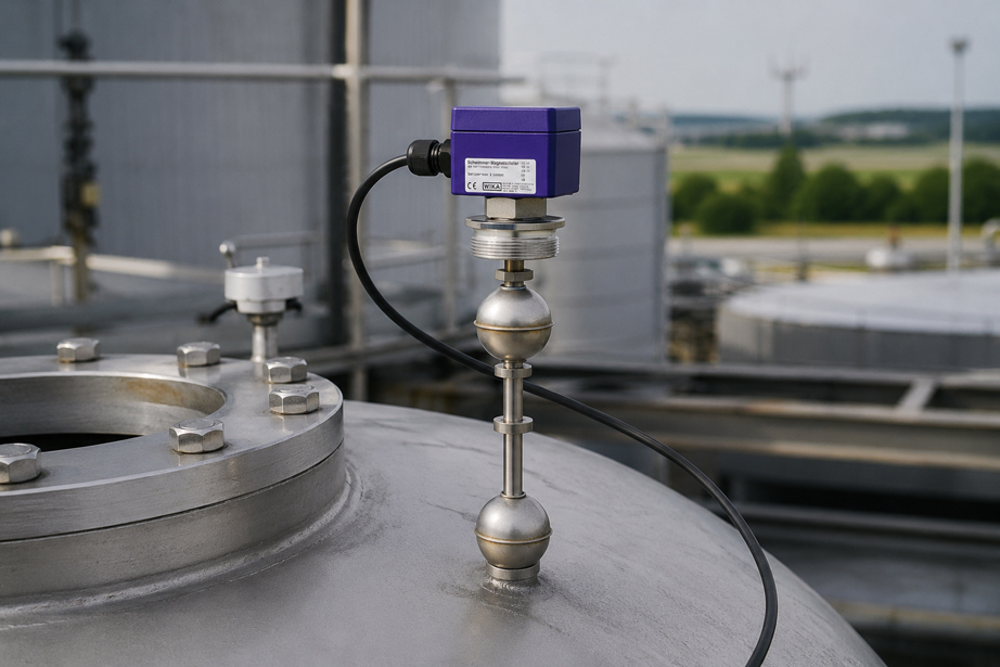
A tank already has continuous level measurement.
The transmitter provides:
4 … 20 mA
to the PLC.
At:
90 %
a High alarm is triggered, and at:
95 %
the filling process is to be stopped automatically.
Does the tank still need a separate point level switch?
For an independent overfill protection function, evaluating the same continuous level signal alone is often not sufficient.
Because in the event of:
Sensor fault → Incorrect measured value → Incorrect PLC evaluation
the following can all be affected simultaneously:
- level indication,
- control,
- High alarm,
- High-High shutdown
.
A robust system architecture therefore often separates:
continuous process measurement
from:
independent point level detection
.
The continuous measurement provides the current level for indication, control, inventory measurement or the control system.
An additional point level switch, by contrast, monitors only one clearly defined critical point:
High-High / HH
and can trigger a separate alarm or shutdown chain when this level is reached.
The decisive factor is not simply installing two devices in the tank. What matters is how independent the sensor, signal path, logic, power supply and final shutdown element of the protection function actually are.
Suitable continuous level sensors and point level switches can be found at ICS Schneider under Level Measurement Technology.
Table of Contents
- Why continuous measurement and overfill protection perform different tasks
- Distinguishing High, High-High and maximum permissible level
- What does an independent protection layer mean?
- Why a second limit from the same sensor signal is not true redundancy
- Why a separate point level switch is useful
- Use the same or a different measuring principle?
- Considering common-cause failures
- Correctly defining the High-High switching point
- Considering response time and overrun
- Fail-safe behavior of the overfill protection system
- Relay logic and de-energize-to-trip principle
- PLC, safety controller or hardwired shutdown?
- Valve, pump or inlet as the final shutdown element
- Medium properties when selecting the point level switch
- Foam, deposits and turbulence
- Mounting position of the point level switch
- Overfill protection and WHG/AwSV
- Correctly classifying SIL and functional safety
- Functional testing and proof testing
- Managing bypasses and maintenance overrides
- Still using diagnostics from continuous measurement
- Recommended planning and testing procedure
- Typical error patterns
- Practical example: storage tank with continuous measurement and HH shutdown
- Suitable ICS products
- Conclusion
- FAQ
Why continuous measurement and overfill protection perform different tasks
Continuous level measurement answers the question:
How full is the vessel currently?
It is typically used for
- level indication,
- inventory monitoring,
- pump control,
- process control,
- volume calculation,
- remote monitoring,
- process optimization.
Point level detection, by contrast, only answers
Has the defined point level been reached – yes or no?
This simplification is intentional
A High-High point level switch does not need to know whether the tank is currently:
61 %, 72 % or 84 %
full.
It must reliably detect:
critical level reached
The tasks are therefore fundamentally different
| Continuous measurement | Point level detection |
|---|---|
| Provides a continuous measured value | Provides a binary switching state |
| Indication and control | Alarm or shutdown |
| e.g. 4–20 mA / HART | e.g. contact, relay, NAMUR |
| Measuring range over tank height | Fixed switching point |
| Process control | Limit monitoring |
Important
High-quality continuous level measurement does not automatically make an independent point level switch unnecessary.
Distinguishing High, High-High and maximum permissible level
Several level limits are often defined in industrial systems.
Normal operating range
For example:
20 … 80 %
High – H
A high level may initially trigger an operating alarm.
Example:
H = 85 %
High-High – HH
An additional higher limit can initiate a protective action.
Example:
HH = 92 %
Above this point
there must still be sufficient safety margin to accommodate:
- response times,
- valve closing time,
- pump overrun,
- pipeline contents,
- communication delays
.
Therefore, the following does not apply
HH = top of tank
Instead
The High-High point must be positioned low enough that the system can still respond safely after it is triggered before an impermissible condition is reached.
What does an independent protection layer mean?
The term:
independent
is often interpreted too simplistically in practice.
Two sensors in the vessel alone are not sufficient
The protection function may still have common elements such as:
- the same power supply,
- the same PLC input module,
- the same PLC,
- the same software logic,
- the same terminal block,
- the same cable route,
- the same process connection,
- the same shut-off valve.
Depending on the required safety function
several levels must therefore be considered:
Sensor → Signal line → Evaluation → Logic → Output → Final shutdown element
A meaningful separation may include, for example
- a separate point level sensor,
- a separate connection cable,
- separate evaluation,
- defined fail-safe behavior,
- a dedicated alarm or shutdown path.
Important
The extent to which this independence is required depends on:
- risk assessment,
- medium,
- system concept,
- legal requirements,
- required safety integrity
.
Why a second limit from the same sensor signal is not true redundancy
A common architecture looks like this:
Level transmitter → 4–20 mA → PLC
and within the PLC:
85 % → High alarm
92 % → High-High shutdown
This can be perfectly reasonable for process operation
but both functions depend on the same:
- measuring principle,
- sensor,
- analog output,
- cable,
- analog input
.
Example
Due to incorrect configuration, a radar level sensor continuously indicates:
70 %
although the tank is actually already:
94 %
full.
In this case, neither
High
nor:
High-High
may be detected.
The second software limit
is therefore:
an additional evaluation of the same measurement signal, but not automatically an independent measuring system.
Why a separate point level switch is useful
A separate point level switch monitors the critical level directly at a defined position.
Example
The continuous measurement provides:
0 … 100 %
via an analog transmitter.
In addition, at
HH = 92 %
a dedicated point level switch is installed.
This creates two information paths
continuous level → process control
and:
HH point level → protective action
Advantage
An error in the scaling of the continuous measuring system does not automatically have to affect the point level switch.
Other possible errors of the continuous measuring system
- incorrect tank linearization,
- incorrect zero point,
- incorrect measuring range,
- software error,
- incorrect PLC scaling
can therefore be partially decoupled from HH detection.
Use the same or a different measuring principle?
A separate sensor can operate according to the same or a different physical measuring principle.
Example
Continuous measurement:
80-GHz radar
Overfill protection:
float switch
Or
Continuous measurement:
magnetostrictive float
Point level:
vibrating level switch
Different measuring principles can help
reduce common failure mechanisms.
Example: radar + float
Unfavorable echo evaluation by the radar does not directly influence the mechanically or magnetically operating point level switch.
However
Different measuring principles are not automatically always better.
The second measuring principle must still be suitable for the:
- medium,
- pressure,
- temperature,
- tank design,
- switching point
.
Considering common-cause failures
Even two different sensors can be affected simultaneously by the same cause.
Typical common failure causes
| Common cause | Possible effect |
|---|---|
| Both sensors installed at an unsuitable tank position | Both detect the local level incorrectly |
| Heavy product buildup | Several sensors may be affected |
| Common power supply fails | Both signals may be lost |
| Common PLC fails | Measurement and shutdown are affected simultaneously |
| Common shut-off valve is blocked | Shutdown does not work despite a correct sensor signal |
| Incorrect tank data in the design | Switching points of both systems defined incorrectly |
Therefore
the question should not only be:
Do we have two sensors?
but rather:
Which failures could render both protection paths ineffective simultaneously?
Correctly defining the High-High switching point
The HH switching point should not be selected solely on the basis of a convenient percentage.
The following must be taken into account
- maximum permissible level,
- tank geometry,
- inflow quantity,
- maximum filling flow rate,
- valve closing time,
- pump overrun,
- pipeline volume,
- measurement and switching delays,
- process fluctuations.
Important for non-linear vessels
In a horizontal cylindrical tank or spherical tank:
10 % additional fill height
does not necessarily mean:
10 % additional volume
The safety margin
should therefore preferably be based on:
actual remaining volume
and:
maximum possible inflow
.
Considering response time and overrun
After the point level sensor switches, the inflow does not stop immediately.
The total response time may consist, for example, of
ttotal = tSensor + tLogic + tValve + tOverrun
During this time
medium continues to flow into the tank.
Simplified estimate
With a maximum net inflow:
Qmax
and an available remaining volume:
ΔV
the theoretical reserve time is:
tReserve = ΔV / Qmax
Example
Between the HH switching point and the maximum permissible level, there is still:
400 l
available.
The maximum inflow is:
200 l/min
The theoretical reserve is therefore
400 l / 200 l/min = 2 min
These two minutes
must be sufficient, among other things, for:
- sensor response,
- logic processing,
- valve closing,
- pump run-down,
- continued inflow from the pipeline volume.
This makes it clear
The switching point is part of the safety-related design and not merely a parameter setting in the control cabinet.
Fail-safe behavior of the overfill protection system
An important question is:
What happens in the event of a fault?
Examples
- cable break,
- power failure,
- sensor fault,
- relay fault,
- failure of the evaluation unit.
Unfavorable architecture
The safe state is generated exclusively by an:
actively present switching signal
.
In the event of a cable break, this signal is no longer received.
Fail-safe-oriented architecture
can instead be designed so that a defined fault results in:
Alarm / Shutdown
.
Which behavior is correct
must be defined for the respective safety function.
Fail-safe does not simply mean “normally closed instead of normally open”; the complete failure scenario from the sensor to the final shutdown element must be considered.
Relay logic and de-energize-to-trip principle
For binary protection functions, the de-energize-to-trip principle is often considered.
Basic idea
In the normal state, the relay is:
energized
In the event of
- HH level reached,
- power supply failure,
- certain line faults
it de-energizes.
Advantage
A loss of energy can therefore more readily be detected as a fault.
However
the correct electrical architecture depends on the sensor used and its output.
With:
- potential-free reed contacts,
- NAMUR signals,
- transistor outputs,
- relay outputs
different evaluation principles may be required.
PLC, safety controller or hardwired shutdown?
An HH point level switch does not necessarily have to switch a valve directly.
Possible architecture
Point level switch → Evaluation relay → Shut-off valve
Or
Point level switch → Safety controller → Shut-off valve
Or for less critical process functions
Point level switch → PLC → Alarm
Which variant is suitable
depends on the required protection function and its risk assessment.
Important for true independence
If both the continuous measurement and the separate HH point level switch are routed through:
the same standard PLC
it must be checked whether the desired independence is actually achieved.
Valve, pump or inlet as the final shutdown element
The overfill protection chain does not end at the point level switch.
The sensor can trigger correctly
but the tank may still be overfilled if:
- the inlet valve is stuck,
- the pump continues to run,
- a contactor has welded contacts,
- inflow continues through a second line.
The complete function is therefore
Detect point level → Evaluate signal → Safely stop inflow
During planning, it must be clarified
- which inflows must be stopped,
- which valve position represents the safe state,
- how quickly the valve closes,
- whether the pump must additionally be switched off,
- whether automatic restart is permissible.
For critical HH shutdowns
a:
latched shutdown state
may also be useful.
The filling process then does not restart automatically as soon as the level falls slightly below the point level switch.
Medium properties when selecting the point level switch
Functional separation is only useful if the point level switch is also physically suitable for the application.
The following should be checked in particular
- density,
- viscosity,
- conductivity,
- dielectric constant,
- foaming,
- deposits,
- crystallization,
- solids content,
- temperature,
- pressure,
- chemical resistance.
For a float switch
the:
minimum medium density for the float
is a critical parameter.
A float
that does not generate sufficient buoyancy in the medium cannot reliably reach the intended switching point.
For a vibrating level switch
other medium properties and possible deposits play a role.
Foam, deposits and turbulence
An overfill protection device is often installed in the upper area of the tank.
The following may occur there
- foam,
- splashes,
- inlet jets,
- condensate,
- deposits.
Installation directly next to the inlet
can, for example, cause a sensor to be temporarily affected by the inlet jet even though the actual tank level is still below the switching point.
Conversely
heavy deposits can impair detection of the actual point level.
Therefore
the mounting position should be:
- representative of the tank level,
- accessible for testing,
- as free as possible from direct inflow
.
Mounting position of the point level switch
The geometric height of the switch is directly part of the protection function.
The following must be considered
- sensor insertion length,
- float geometry,
- switching point relative to the process connection,
- tank roof,
- nozzle height,
- gasket,
- mounting flange.
A common mistake
is the assumption:
Process connection at 9,000 mm = Switching point at 9,000 mm
This does not have to be the case
because the actual switching point may, by design, be:
below or above the reference point of the connection
.
Therefore
the actual switching point should be determined from:
- drawing,
- insertion length,
- device configuration
.
Overfill protection and WHG/AwSV
For systems containing substances hazardous to water, the term:
overfill protection
can have a specific legal meaning.
In this case, it is not automatically sufficient
to use any industrial level switch.
The following must be checked
- specific application,
- medium,
- vessel,
- applicable requirements under WHG and AwSV,
- approval of the system used,
- permitted device configuration,
- required testing and documentation.
WIKA FLS
The WIKA data sheet available from ICS lists DIBt approvals for use as an overfill protection device for certain versions of:
FLS-S
.
Important
The approval must not be applied generally to every FLS version or every circuit built using it.
Before selection, the specific:
- model variant,
- float version,
- electrical evaluation,
- approval,
- installation conditions
must be checked.
Correctly classifying SIL and functional safety
In process plants, the overfill shutdown can be part of a:
Safety Instrumented Function – SIF
.
Sensor, logic and actuator must then be considered together
Sensor → Logic Solver → Final Element
A sensor suitable for SIL applications therefore does not automatically mean
that the complete overfill protection function fulfills:
SIL 2
or:
SIL 3
.
Additional relevant factors include
- architecture,
- failure probabilities,
- diagnostics,
- proof-test interval,
- common-cause failures,
- logic system,
- shut-off valve.
Siemens SITRANS LVL200
is listed by ICS as a vibrating point level switch for:
- overflow protection,
- dry-run protection,
- full and empty indication
and, depending on the version, offers options or support for safety-related applications.
For the specific safety function
the following must always be evaluated:
exact device version + certification + system architecture
.
Functional testing and proof testing
A protection function that has not been triggered for years can still have an undetected fault.
It should therefore be tested regularly
and as completely as possible:
Sensor → Signal evaluation → Shutdown
A visual inspection alone is not sufficient
The point level switch may appear externally intact and still be:
- mechanically blocked,
- electrically defective,
- incorrectly wired
.
A complete functional test should check
- switching point,
- switching function,
- alarm transmission,
- latching,
- pump shutdown,
- valve response,
- fault indication.
For safety-related applications
the scope and interval of testing must be derived from the respective safety assessment or approval.
Managing bypasses and maintenance overrides
For maintenance work, it may be necessary to temporarily bypass an HH shutdown.
This creates a significant risk
if the bypass remains:
active
after maintenance.
Good system organization should therefore include
- clear bypass indication,
- documented authorization,
- time limitation,
- reset after maintenance,
- final functional test.
A dangerous condition would be
Sensor operational + Protection logic bypassed = No shutdown
Therefore
Organizational management of bypasses is part of a reliable protection function.
Still using diagnostics from continuous measurement
Separating the protection function does not mean that continuous measurement is of no value for safety.
On the contrary
it can provide additional information.
Example
Continuous level:
93 %
but HH point level switch:
not activated
This is an important plausibility conflict
and can indicate:
- incorrect scaling,
- incorrect switching point,
- sensor fault,
- mechanical blockage
.
Conversely
the HH point level switch reports:
HIGH-HIGH
but the continuous sensor indicates:
68 %
In this case, the system
should not simply ignore one of the two values.
The discrepancy itself is:
diagnostic information
Recommended planning and testing procedure
- Define the medium: Record density, viscosity, conductivity, foaming, deposits, temperature and pressure.
- Record tank geometry: Document height, volume, roof shape, nozzles and inlet position.
- Determine normal operating range: Define the desired minimum and maximum operating levels.
- Define maximum permissible level: Consider process and legal requirements.
- Define High alarm: Specify an early warning before the critical range is reached.
- Determine High-High switching point: Provide sufficient distance from the maximum permissible level.
- Determine maximum inflow: Consider the worst-case filling flow rate.
- Calculate overrun: Consider valve closing time, pump overrun and pipeline contents.
- Select continuous measuring principle: Define a measurement method suitable for the process and vessel.
- Select separate point level switch: Consider medium, pressure, temperature and switching point.
- Compare measuring principles: Identify common failure mechanisms.
- Check mechanical independence: Determine a separate and suitable mounting position.
- Define electrical architecture: Specify power supply, wiring and signal path.
- Define fail-safe behavior: Determine the response to cable break, power failure and device fault.
- Define logic system: Select standard PLC, safety controller or separate evaluation according to the risk assessment.
- Define final element: Determine valve, pump or another means of interrupting the inflow.
- Define restart behavior: Specify automatic reset or manual acknowledgement.
- Check approvals: Verify the exact device version for WHG/AwSV, Ex or SIL applications.
- Define functional test: Specify the test method for the sensor and complete shutdown chain.
- Document test interval: Include recurring testing in the maintenance plan.
- Define bypass procedure: Manage overrides in a controlled manner.
- Perform commissioning: Check the actual switching point and complete protective response.
- Create documentation: Record switching point, device types, logic and testing procedure.
Typical errors with overfill protection systems
| Observation | Possible cause | Recommended check |
|---|---|---|
| High and High-High fail simultaneously | Both limits are derived from the same transmitter | Check independent point level switch |
| HH switch responds too late | Switching point set too high | Calculate remaining volume and response time |
| Tank continues to fill despite HH alarm | Valve or pump does not respond | Test complete shutdown chain |
| Float switch does not activate | Density or freedom of movement unsuitable | Check float design and deposits |
| Point level switch triggers sporadically during filling | Inlet jet or strong turbulence | Check mounting position |
| Sensor shows permanent alarm after maintenance | Installation or switching logic changed | Check installation and contact function |
| Cable break remains undetected | No suitable fail-safe evaluation | Check signal and relay concept |
| Protection function does not operate during test | Bypass still active | Check bypass management |
| Continuous value and HH signal contradict each other | Scaling, sensor or installation error | Check both measuring systems separately |
| Sensor has suitable technology but may not be used as a legally required overfill protection device | Required approval is missing | Check exact device version and approval documentation |
| Both sensors fail simultaneously | Common power supply or common failure cause | Evaluate independence of the complete architecture |
Practical example: storage tank with continuous measurement and HH shutdown
A storage tank is filled by a pump.
The operator requires:
- continuous level indication,
- High alarm,
- independent High-High shutdown.
Continuous measurement
For continuous level measurement, a:
4–20 mA level transmitter
is used.
The PLC uses the measured value for
- indication,
- trend recording,
- inventory monitoring,
- High alarm at 85 %.
Separate HH switch
At:
92 %
a dedicated point level switch is installed.
This point level switch
is not part of the analog level measurement chain.
When it is activated
the following occurs:
HH → Filling pump OFF + Inlet valve CLOSED + Alarm
The condition is latched
and must be manually acknowledged after the cause has been investigated.
Reserve volume
Between HH and the maximum permissible level, there is:
500 l
available.
Maximum inflow
150 l/min
Theoretical reserve time
500 / 150 = 3,33 min
It must now be checked
whether:
Sensor response + Logic + Pump shutdown + Valve closing time + Overrun
remain safely within this reserve.
Functional test
During commissioning, not only the contact of the point level switch is tested.
The complete chain is tested
Point level → Switching signal → Logic → Pump OFF → Valve CLOSED → Alarm
Result
Continuous measurement provides the convenient process value, while separate HH detection performs an independent protection task. The two functions complement each other instead of merely evaluating the same measurement chain several times.
Suitable ICS products for continuous measurement and independent point level detection
WIKA Type FLS – Float Switch for the Process Industry
For separate point level detection, ICS offers the:
Operating principle
A float with a permanent magnet moves along a guide tube.
Inside the tube is a:
reed contact
which is activated when the defined level is reached.
ICS specifies, among other things
- vertical installation,
- potential-free contacts,
- several possible switching points,
- normally open, normally closed or changeover contacts,
- temperatures up to +350 °C depending on the version,
- process pressures from vacuum to 40 bar,
- minimum medium densities from 300 kg/m³,
- various materials and process connections,
- explosion-protected versions.
Particularly useful for overfill protection
is the ability to implement a physically defined:
MAX / HH switching point
independently of continuous measurement scaling.
WHG applications
The WIKA data sheet available on the ICS website lists DIBt approval for overfill protection systems for certain FLS-S versions.
For a specific WHG/AwSV application, the exact permissible device configuration must be checked.
Siemens SITRANS LVL200 – Vibrating Point Level Switch
Another solution listed by ICS is the:
ICS describes it as a
vibrating point level switch for liquids and slurries for:
- overflow monitoring,
- dry-run protection,
- full indication,
- empty indication,
- pump monitoring.
Particularly useful for protection functions are
- test function including remote options,
- fault monitoring for corrosion,
- monitoring of vibration failure,
- monitoring for cable break to the piezo drive,
- various output versions.
ICS specifies the following process ranges
-196 … +450 °C
and:
-1 … 160 bar g
Depending on the version
additional safety-related approvals or options are available.
WIKA Type FLM-CA – Continuous Level Measurement
For continuous process measurement, ICS offers the:
The instrument is designed
for high-accuracy continuous level measurement of liquids using the:
magnetostrictive measuring principle
ICS specifies
- 4 … 20 mA according to NAMUR NE43,
- optionally HART® version 6,
- guide tube lengths from 100 mm to 3 m,
- temperature range -40 … +250 °C,
- pressure range from vacuum to 40 bar,
- minimum medium density ≥ 580 kg/m³,
- optionally explosion-protected version.
Typical division of tasks
FLM-CA → continuous process value
FLS or LVL200 → separate point level
Siemens SITRANS LR100 Series – Non-Contact Radar Level Measurement
For non-contact continuous measurement, ICS also lists the:
.
The series operates with
80-GHz radar
ICS specifies, among other things
- narrow beam angle,
- measurement of liquids and bulk solids,
- Bluetooth® for commissioning,
- HART or, depending on the version, Modbus RTU,
- measuring ranges up to 30 m depending on the version.
For the architecture described here
for example:
SITRANS LR100 → continuous measurement
could be combined with:
FLS or SITRANS LVL200 → separate HH point level
.
Which solution is suitable?
| Task | Suitable ICS solution |
|---|---|
| Continuous liquid level measurement using a float principle | WIKA FLM-CA |
| Non-contact continuous level measurement | Siemens SITRANS LR100 Series |
| Separate MAX/HH switching point with float | WIKA FLS |
| Separate point level detection using the vibrating principle | Siemens SITRANS LVL200 |
| Application with WHG/AwSV requirements | Use only an exactly approved device and system configuration after checking the approval documentation |
| Safety-related overfill shutdown | Evaluate sensor, logic, actuator and required safety integrity as one complete system |
An overview of all solutions can be found under Level Measurement Technology at ICS Schneider.
Conclusion
Continuous level measurement and an overfill protection system perform different tasks.
Continuous measurement provides the process value
For example, it indicates:
Level = 73,4 %
and can be used for:
- indication,
- control,
- trending,
- inventory monitoring
.
Independent point level detection monitors a critical point
For example, it determines:
HH reached → Stop filling
A second software limit is not automatically a second protection layer
If High and High-High are derived from the same sensor and the same 4–20 mA signal, many common failure causes remain.
A separate point level switch reduces this dependency
especially when the following are also considered in accordance with the required protection function:
- signal path,
- evaluation,
- power supply,
- shutdown logic
.
The HH switching point requires reserve
It must be positioned low enough that sufficient time and volume remain after activation for:
- signal processing,
- pump shutdown,
- valve closing,
- overrun
.
Fail-safe applies to the complete chain
Not only the sensor but the complete:
Sensor → Line → Logic → Actuator
must be considered.
An approved component alone is not yet a complete approved overfill protection system
For WHG/AwSV or SIL requirements, the specific device version, approval and system architecture are decisive.
For practical applications
Define normal level range → define maximum permissible level → plan High and High-High separately → determine maximum inflow and overrun → select continuous measuring principle → specify separate point level switch → check common failure causes → determine mounting position → define fail-safe concept → define signal path and logic → evaluate final shutdown element → check approvals → verify actual HH switching point during commissioning → functionally test the entire shutdown chain → document proof-test and maintenance intervals.
FAQ: Planning Overfill Protection Independently of Level Measurement
What is an overfill protection system?
An overfill protection system is intended to prevent a vessel from being filled beyond a permissible level. Depending on the application, this may be a simple operational protection function or a legally or safety-related defined protection function.
What is the difference between level measurement and point level detection?
Continuous level measurement continuously provides the current level. A point level switch, by contrast, detects only when a defined switching point is reached.
What does High-High mean?
High-High or HH usually refers to a particularly high level at which a defined protective action is triggered, such as switching off a pump or closing an inlet valve.
Is a High alarm the same as overfill protection?
Not necessarily. A High alarm may merely provide a warning to operating personnel. An overfill protection function may additionally require automatic shutdown.
Can I generate the High-High limit from my 4–20 mA level signal?
Technically, yes. This may be useful for process operation. However, if an independent protection function is required, it must be checked whether the shared use of the same sensor, signal path and logic system is sufficient.
Why is a second PLC limit not complete redundancy?
Because both limits still depend on the same sensor and its measurement signal. A common sensor fault can therefore affect both limit functions simultaneously.
Why should a separate point level switch be used?
It enables a critical level to be detected independently of the continuous measured value and therefore reduces certain common failure causes.
Does the point level switch have to use a different measuring principle?
Not necessarily. However, a different physical measuring principle can help reduce certain common failure mechanisms. The measuring principle must still be suitable for the medium and process.
What is a common-cause failure?
This refers to a common cause that simultaneously affects several components or protection paths that are otherwise intended to be separate.
What is an example of a common-cause failure?
If the continuous sensor and point level switch are supplied from the same power source and that source fails, both systems can be affected simultaneously.
How is the High-High switching point defined?
It must be selected so that sufficient volume and response time remain between activation and the maximum permissible level to completely stop the inflow.
Why should HH not be located directly at the top of the tank?
Because medium may continue to flow in after activation until pumps and valves actually respond.
How do I calculate the available reserve time?
In simplified form, tReserve = ΔV / Qmax can be used, where ΔV is the available remaining volume and Qmax is the maximum net inflow.
What is included in the response time?
Among other things, sensor response, signal processing, logic, valve closing time, pump overrun and, where applicable, continued inflow from pipeline contents.
What does fail-safe mean for an overfill protection system?
The protection function should be designed so that relevant faults lead, wherever possible, to a defined safe or detectable state.
Is a normally closed contact automatically fail-safe?
No. The complete signal chain including power supply, evaluation and actuator must be considered.
What is the de-energize-to-trip principle?
In the normal condition, for example, a relay is kept energized. When the protection function is triggered or certain faults occur, it de-energizes. Whether this principle is suitable depends on the specific circuit.
Should an HH shutdown reset automatically?
This depends on the risk assessment. For critical protection functions, a latched shutdown with deliberate manual acknowledgement may be useful.
Does a valve also need to close in addition to switching off the pump?
This depends on the system. The decisive factor is that all relevant inflow paths are reliably interrupted.
Why must the shut-off valve also be tested?
Because a correctly triggered point level sensor does not prevent overfilling if the valve fails to close mechanically.
What is a proof test?
A proof test is a recurring functional test of a protection function intended to reveal dangerous failures that are not detected during normal operation.
Should only the point level switch be tested?
To assess the complete protection function, the entire chain from the point level sensor to the actual shutdown response should be tested wherever possible.
What must be considered with a maintenance bypass?
An active bypass must be clearly identifiable, released in a controlled manner and removed again after the work has been completed. The protection function should then be tested again.
Can continuous measurement be used for plausibility checking?
Yes. Discrepancies between the continuous measured value and the binary point level signal can provide valuable diagnostic information.
Which measuring principles are suitable for continuous level measurement?
Depending on the application, suitable principles include radar, ultrasonic measurement, hydrostatic measurement, magnetostrictive float systems, reed chains or guided wave radar.
Which measuring principles are suitable for point level detection?
Depending on the medium, suitable options include floats, vibrating level switches, optoelectronic, capacitive or conductive point level sensors.
When is a float switch suitable?
Float switches are particularly robust solutions for liquids when density, temperature, pressure and mechanical installation conditions are suitable for the selected float.
Why is density important for a float switch?
The float must generate sufficient buoyancy in the respective medium so that the intended switching point is reliably reached.
What is the WIKA FLS?
The WIKA FLS is a float switch listed by ICS for industrial process applications with vertical installation.
How does the WIKA FLS work?
A float with a permanent magnet moves along a guide tube and actuates reed contacts located inside it.
Which contact types does the FLS offer?
Depending on the version, normally open, normally closed or changeover contacts are available.
Can the WIKA FLS have multiple switching points?
Yes. ICS also lists the FLS with several configurable switching points.
Can the WIKA FLS be used as an overfill protection device?
For certain FLS-S versions, the available WIKA documentation lists corresponding DIBt approvals. For the specific application, however, the exact approved device and system version must be checked.
What is the Siemens SITRANS LVL200?
The SITRANS LVL200 is a vibrating point level switch for liquids and slurries that ICS lists, among other things, for overflow and dry-run protection.
Which diagnostic functions does the SITRANS LVL200 provide?
ICS specifies, among other things, a test function including remote options as well as fault monitoring for corrosion, vibration failure and cable break to the piezo drive.
Can the SITRANS LVL200 be used for safety-related applications?
ICS specifies corresponding SIL options or safety-related applications. However, the specific device version and the safety architecture of the complete system must be checked separately.
What is the WIKA FLM-CA?
The FLM-CA is a magnetostrictive level transmitter for high-accuracy continuous level measurement of liquids.
Which output signal does the FLM-CA provide?
ICS specifies 4 … 20 mA according to NAMUR NE43 and optionally HART® version 6.
What is the SITRANS LR100 Series?
The SITRANS LR100 Series consists of compact 80-GHz radar level transmitters for continuous measurement of liquids and bulk solids.
Can I combine SITRANS LR100 with a separate point level switch?
Yes. For example, the radar can provide the continuous process value while a separate float switch or vibrating level switch monitors a defined HH point level.
Is a SIL-capable sensor alone a SIL protection function?
No. Sensor, logic, final shutdown element, architecture and test concept must be evaluated together.
What must be considered for WHG or AwSV applications?
The specifically applicable requirements and the approval of the complete intended overfill protection system must be checked. An arbitrary industrial point level switch must not automatically be regarded as an approved overfill protection device.
Where can I find the WIKA FLS at ICS Schneider?
Further information can be found under WIKA FLS Float Switch at ICS Schneider.
Where can I find the Siemens SITRANS LVL200 at ICS Schneider?
Further information can be found under Siemens SITRANS LVL200 at ICS Schneider.
Where can I find the WIKA FLM-CA at ICS Schneider?
Further information can be found under WIKA FLM-CA at ICS Schneider.
Where can I find the SITRANS LR100 Series at ICS Schneider?
Further information can be found under Siemens SITRANS LR100 Series at ICS Schneider.
Where can I find additional level measurement solutions at ICS Schneider?
An overview can be found under Level Measurement Technology at ICS Schneider.