


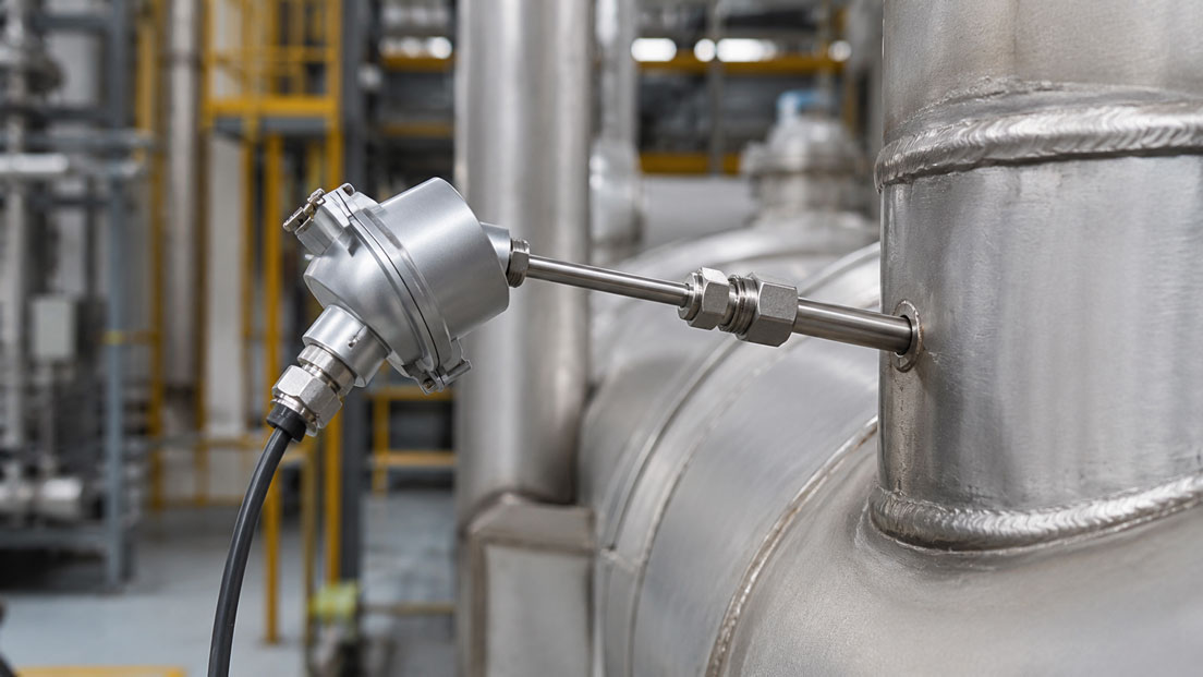
Mineral-insulated thermocouples are used in furnaces, machines, process plants, test benches, exhaust ducts, tools and many other industrial applications. They are compact, temperature-resistant, comparatively robust mechanically and, due to their mineral-insulated construction, can often also be used in vibrating environments and at measuring points that are difficult to access.
However, selection is often based only on the thermocouple type and the maximum permissible temperature. These two specifications are not sufficient. A type K thermocouple with a sheath diameter of 1 mm behaves completely differently in the process from a sensor of the same type with a diameter of 6 mm. The thinner version responds faster and is easier to route, but offers less mechanical reserve. The larger diameter is more robust, but requires more time to follow a temperature change.
The junction design, sheath material, immersion depth, process connection, installation angle and any additional thermowell also influence the measurement result. The bending radius must not be underestimated either. Although a mineral-insulated cable can be formed, it must not be bent excessively sharply, repeatedly or directly at the measuring tip.
This article explains the construction of a mineral-insulated thermocouple, compares typical sheath diameters, shows the differences between grounded and insulated junctions and explains what must be considered regarding bending, process connection, cable length and mechanical loading.
Table of contents
- Why the temperature range alone is not sufficient
- How a mineral-insulated thermocouple is constructed
- Selecting the appropriate thermocouple type
- How the sheath diameter affects performance
- How the diameter influences the response time
- Grounded, insulated and exposed junctions
- Selecting the sheath material to suit the application
- Bending a mineral-insulated thermocouple correctly
- Considering immersion depth and heat dissipation
- Measurement in bores and solid bodies
- Selecting the process connection and mounting method
- Direct measurement or an additional thermowell?
- Cable length, transition and connection cable
- Vibration, flow and mechanical loading
- Electrical connection and cold-junction compensation
- Direct comparison of sheath diameters
- Correct installation in practice
- Typical selection and installation errors
- Practical example: Delayed temperature control in an industrial furnace
- Commissioning and functional testing
- Which measuring instruments / products are suitable?
- Conclusion
- Frequently asked questions about mineral-insulated thermocouples
Why the temperature range alone is not sufficient
The thermocouple type defines the two thermoelectric materials from which the conductors are made and the thermoelectric voltage characteristic that is used. Among other things, it influences the usable temperature range, sensitivity, long-term stability and suitability for certain atmospheres.
However, the permissible use of a complete mineral-insulated thermocouple is not determined by the thermocouple type alone. The diameter of the thermocouple wires, sheath material, process atmosphere, installation position and duration of the temperature exposure are also decisive.
A temperature value from a general comparison table is therefore not automatically the permissible continuous operating temperature of every specific sensor version. Although a very thin mineral-insulated thermocouple can provide a fast response, it has less material reserve against oxidation, corrosion and mechanical wear at high temperatures.
Components outside the actual mineral-insulated section must also be considered. The transition sleeve, connection cable, plug connector, cable gland and connection head frequently have considerably lower permissible temperatures than the metallic sensor sheath. These components must be located outside the hot zone or designed accordingly.
For correct selection, at least the thermocouple type, sheath diameter, sheath material, junction type, insertion length, process connection and connection design must therefore be considered together.
How a mineral-insulated thermocouple is constructed
At its core, a mineral-insulated thermocouple consists of two thermocouple wires made from different metal alloys. These conductors are joined together at the measuring tip. Due to the Seebeck effect, a thermoelectric voltage is generated that depends on the temperature difference between the measuring junction and reference junction.
In a mineral-insulated version, the thermocouple wires run inside a metallic outer sheath. A highly compacted mineral insulation, usually based on a ceramic insulating material, is located between the conductors and between the conductors and sheath.
This construction is often referred to as an MI cable. MI stands for “mineral insulated”. The terms mineral-insulated metal-sheathed cable and MIMS are also used.
The compacted insulating material performs several functions. It keeps the thermocouple wires separated, electrically insulates them from each other and from the sheath, and at the same time supports heat transfer from the outside to the measuring junction.
The metallic sheath protects the internal conductors against mechanical influences and, depending on the selected material, against the process atmosphere, oxidation and corrosion. The complete cable can be manufactured in different diameters, cut to a defined length and, within certain limits, bent into the required shape.
At the cold end, the MI cable transitions into a connection cable, plug connector, connection head or transmitter, depending on the design. This transition is often sealed with a sleeve and potting compound. It is not part of the freely formable high-temperature section and must not be overheated or subjected to high mechanical loads.
Selecting the appropriate thermocouple type
Type K thermocouples are frequently used for general industrial applications. They offer a wide temperature range and are available in numerous designs. For certain high-temperature or long-term applications, type N may be an interesting alternative because of its material properties.
Type J is frequently used in existing installations and in medium temperature ranges. Its application limits and the suitability of the materials used must be considered, particularly in oxidising atmospheres.
Type T is particularly suitable for low temperatures and certain applications in laboratories, refrigeration, food processing and process engineering. Thermocouples made from noble-metal combinations such as types S, R or B are used for very high temperatures. However, these sensors often have a different construction and are not available in every small MI design.
Selection should not be based solely on the maximum process temperature. The following factors are also important:
- continuous or only short-term temperature exposure
- oxidising, reducing or inert atmosphere
- possible process components containing sulphur, carbon or hydrogen
- required tolerance class
- ageing and drift behaviour
- existing evaluation instruments and connection cables
- reference to IEC 60584 or another specification
An existing input configured for type K must not be connected to a type J or N thermocouple without reconfiguration. The thermoelectric voltage characteristics are different. An incorrect input type therefore causes significant measurement errors.
How the sheath diameter affects performance
The sheath diameter is one of the most important variables when selecting a sensor. It influences the response time, mechanical strength, formability, temperature resistance and service life at the same time.
Small sheath diameters have a low thermal mass. This allows the measuring tip to follow a temperature change quickly. They can also be used in small bores, narrow channels and difficult-to-access locations.
However, the smaller material thickness also means less resistance to mechanical loading, abrasion, corrosion and high flow forces. A sensor with a diameter of 0.5 or 1 mm is not suitable for the same mechanical conditions as a sensor with a diameter of 4.5 or 6 mm.
A larger diameter increases stability and can provide a longer service life under harsh operating conditions. At the same time, the thermal mass increases. The measuring junction therefore requires more time to adapt to the temperature of the medium.
The selection is therefore always a compromise. The smallest possible sensor is not automatically the best solution. Likewise, the largest available diameter is not automatically the most robust sensor for every application, because a large cross-section can cause greater heat conduction errors and mechanically influence the process.
How the diameter influences the response time
The response time describes how quickly a temperature sensor follows a temperature change. Values such as t50, t63 or t90 are frequently used for this purpose. They indicate the time after which the sensor has reached 50, 63 or 90 percent of the final temperature change.
A response time is never solely an unchanging property of the sensor. It also depends on the test medium, flow velocity, temperature difference and installation situation.
A sensor normally reacts considerably faster in moving water than in still air. A value stated in a data sheet therefore cannot simply be transferred to a furnace, pipeline or bore in a metal block.
In principle, a smaller sheath diameter shortens the response time. The wall thickness of the sheath, position of the measuring junction and heat conduction between the junction and outer sheath also influence the dynamic behaviour.
A thermowell can significantly reduce the speed advantage of a thin mineral-insulated thermocouple. The heat must then first pass through the thermowell, possibly an air gap and subsequently the sheath of the thermocouple.
An excessively large bore in a solid body also delays the measurement. The air gap between the sensor and bore wall acts as thermal insulation. The sensor then measures its own environment inside the bore more strongly than the actual component temperature.
For fast control processes, the solution is therefore not simply to select the thinnest possible sensor. The entire thermal measuring chain, including the installation point, contact surface and protective construction, must be considered.
Grounded, insulated and exposed junctions
In a mineral-insulated thermocouple, the actual measuring junction can be connected to the metallic outer sheath in different ways. The two most important versions are the grounded and insulated junction.
Grounded junction
With a grounded junction, the connection between the two thermocouple wires is electrically and thermally connected to the base or sheath of the measuring tip.
Due to the direct thermal contact, a grounded junction typically reacts faster than an insulated version with an identical diameter. It is therefore well suited to dynamic measurements where a fast response is particularly important.
However, the metallic sheath and measuring junction are at the same electrical potential. If the sheath is connected to an earthed machine or pipeline, this can cause ground loops, equalising currents or interference.
Whether a grounded junction can be used therefore also depends on the input of the measuring instrument, galvanic isolation and the grounding concept of the installation.
Insulated junction
With an insulated junction, the connection between the thermocouple wires is separated from the outer sheath within the mineral insulation. This design is also referred to as an ungrounded junction.
The electrical isolation reduces the risk of ground loops and can be advantageous in earthed machines, electrically heated systems, installations with variable frequency drives or applications with several measuring points connected to one evaluation instrument.
Because the heat must pass through the gap or insulating layer between the sheath and measuring junction, the response is usually slightly slower than that of a grounded junction with the same diameter.
This speed disadvantage can be partially compensated for by selecting a smaller sheath diameter. However, the final selection must consider both the dynamic behaviour and electrical measurement reliability.
Exposed junction
With an exposed junction, the connection point of the thermocouple wires is located outside the protective sheath. This design can respond particularly quickly, but has very little mechanical or chemical protection.
It is only suitable for applications without high pressures, aggressive media, strong flows or mechanical contact. It is therefore considerably less common in industrial process plants than grounded or insulated sheathed tips.
| Junction type | Response behaviour | Electrical isolation | Typical suitability |
|---|---|---|---|
| Grounded | Fast | No | Dynamic measurement with a controlled grounding concept |
| Insulated | Slightly slower | Yes | Electrically noisy installations, earthed components and multiple measuring channels |
| Exposed | Very fast | Depending on the construction | Clean, dry, unpressurised and mechanically non-critical environments |
Selecting the sheath material to suit the application
The metallic sheath is in direct contact with the process or surrounding atmosphere. Its suitability is therefore just as important as the thermocouple type.
Stainless steels are frequently used at moderate to elevated temperatures and in many general industrial applications. Nickel-based alloys such as Alloy 600 or comparable materials offer advantages at higher temperatures and in certain corrosive atmospheres.
However, a general statement about media compatibility is not sufficient. Suitability depends on the medium, concentration, temperature, pressure, flow velocity and exposure time.
Atmospheres containing sulphur, reducing atmospheres or strongly carburising atmospheres can be particularly critical. Chlorides, acids, alkalis and hot combustion gases can also attack certain sheath materials.
With abrasive media, chemical resistance is not the only factor to assess. Particles at high flow velocities can mechanically erode a thin sheath. In this case, a larger diameter, a thermowell or a different installation position may be required.
The final material selection must be confirmed by the plant operator on the basis of the actual process conditions. A general compatibility table cannot replace an application-specific assessment.
Bending a mineral-insulated thermocouple correctly
Mineral-insulated thermocouples can generally be formed. This property simplifies installation in confined machines, furnaces or along curved components.
However, formable does not mean infinitely flexible. The permissible minimum bending radius depends on the diameter, sheath material, sensor construction and manufacturer. Depending on the version, typical manufacturer specifications are approximately three to five times the sheath diameter.
With a sheath diameter of 3 mm, a required radius of five times the diameter would, for example, be 15 mm. The radius refers not to the diameter of the complete bend, but to the distance from the centre of the imaginary circular arc to the centreline of the cable.
The specification in the data sheet of the specific thermocouple is always decisive. A general rule of thumb must not be used if the manufacturer specifies a larger radius.
The measuring tip must generally not be bent. The sensitive connection point of the thermocouple wires is located there. Deformation can damage the measuring junction, insulation or closed end of the sheath.
The transition between the MI cable and connection cable must also not be bent or used as a leverage point. This area contains the seal, potting compound and electrical connection to the connecting conductors.
The bend should be produced with a suitable radius and, wherever possible, in a single operation. Repeated back-and-forth bending causes work hardening and material fatigue. Even if the sheath appears undamaged externally, the thermocouple wires or insulation distances inside may have been impaired.
A thermocouple that has already been sharply kinked should not simply be bent back and reused. For safety-related or quality-critical measuring points, an electrical inspection or replacement is advisable.
Considering immersion depth and heat dissipation
A temperature sensor does not automatically measure the exact temperature of the medium simply because its tip extends into the process. Insufficient immersion depth can cause heat to be conducted away through the sheath and process connection.
The measuring tip is then influenced by the cooler environment, connection thread or vessel wall. For example, the indicated value may be below the actual gas temperature in a furnace or above the actual temperature in a refrigeration application.
As general guidance, an immersion depth of several sheath diameters is frequently required. However, the actual value depends on the medium, flow, temperature difference, sheath material and installation design.
A greater immersion depth is generally required in gases than in liquids. Gases transfer heat less efficiently, meaning that heat dissipation along the sensor can have a stronger influence.
In pipelines, the measuring tip should extend into an area with representative flow. Installation immediately adjacent to the pipe wall may result in a measured value that is influenced more strongly by the wall temperature than by the temperature of the medium.
At the same time, the sensor must not extend so far into a fast flow that impermissible bending forces occur. Measurement quality and mechanical strength must be assessed together.
Measurement in bores and solid bodies
Mineral-insulated thermocouples are frequently used in bores in tools, heating plates, moulds, bearings, machine housings and test blocks.
The bore diameter should only be slightly larger than the sheath diameter. A large air gap acts as insulation and delays heat transfer.
For certain sensor versions, manufacturers recommend making the bore no more than approximately 1 mm larger than the sensor diameter. However, the specific requirements of the sensor and component are decisive.
The sensor should be inserted as far as possible to the intended measuring point. If only the tip contacts the bore wall while the remaining sensor is freely suspended in the cavity, the response may be unstable and poorly reproducible.
A spring-loaded contact mechanism can improve thermal contact in surface or bore measurements. However, no impermissible force may be applied to the measuring tip.
Thermal compound can improve thermal contact in certain applications. However, its temperature resistance, electrical properties, ageing and possible contamination of the process must be assessed.
Selecting the process connection and mounting method
A mineral-insulated thermocouple can be supplied without a fixed process connection or with a compression fitting, threaded connection, flange, bayonet fitting or customised mounting arrangement.
A plain version without a fixed connection can be inserted flexibly into an existing bore or guide. However, it requires separate strain relief or mounting.
A compression fitting allows the insertion length to be adjusted. Depending on the design, it may be fitted with a metal compression ring or a softer sealing element.
Metal cutting or compression rings can create a pressure-tight connection, but may permanently deform the sheath. Once tightened, the insertion length can often no longer be changed easily.
Softer compression rings may permit repeated positioning, but usually have lower permissible pressure and temperature ranges. The specific load capacity of the fitting must suit the process.
With a fixed threaded connection, it must be considered that the entire sensor rotates while being screwed in. An already bent sensor or connected cable can be damaged as a result.
For pre-bent thermocouples, a rotatable fitting or another mounting method is frequently more suitable than a threaded connection permanently attached to the sheath.
The process connection must also be suitable for the pressure, temperature and medium. A connection suitable for an unpressurised furnace measurement must not be used in a pressurised pipeline without verification.
Direct measurement or an additional thermowell?
A mineral-insulated thermocouple installed directly in the medium normally provides a shorter response time. The process heat reaches the measuring junction directly through the thin metallic sheath.
However, the thermocouple is then directly exposed to pressure, flow, corrosion, abrasion and mechanical loading. In the event of failure, the process may have to be opened or shut down.
An additional thermowell separates the sensor from the process. It often simplifies replacement of the measuring insert and increases mechanical and chemical protection.
However, this adds thermal mass. An air gap may also be present between the thermowell and sensor. The measurement therefore responds more slowly.
A thin mineral-insulated thermocouple in a solid thermowell does not therefore automatically respond quickly. In this construction, the thermowell often determines a large part of the dynamic behaviour.
The decision should be based on pressure, flow, corrosion, replaceability, required response time and safety requirements. In pipelines and at high flow velocities, a strength or vibration calculation of the thermowell is also required.
Cable length, transition and connection cable
The length of the mineral-insulated section determines how far the thermocouple can be inserted into the process and routed outside the hot zone.
The transition sleeve to the flexible connection cable must be located outside its permissible temperature range. If it is positioned too close to a furnace, heating plate or hot pipeline, the potting compound and cable insulation can age prematurely.
The connection cable must match the thermocouple type. Thermocouple and compensating cables have defined material combinations. An ordinary copper cable must not be used arbitrarily as an extension between the thermocouple and evaluation instrument.
Additional material transitions create further thermal junctions. If these transitions are located at different temperatures, unwanted thermoelectric voltages and therefore measurement errors can occur.
Plug connectors must also match the thermocouple type. Miniature connectors for types K, J or T may look similar externally, but use different contact materials and markings.
Electromagnetic interference must be considered with long cable runs. Thermocouples produce only small voltages in the millivolt range. Motor cables, variable frequency drive outputs and contactor cables routed in parallel can therefore induce significant interference.
Shielded cables, separate cable routes, suitable grounding and a galvanically isolated transmitter can improve immunity to interference. The shield connection must match the installation concept.
Vibration, flow and mechanical loading
Mineral-insulated thermocouples are well suited to many vibrating industrial applications. Nevertheless, they are not mechanical components with unlimited load capacity.
A long, thin sensor can vibrate in a fast gas or liquid flow. The alternating bending load is frequently concentrated at the process connection and can cause fatigue cracks there.
The free, unsupported section of the sensor should therefore be kept as short as possible. If necessary, a larger diameter, additional guide or suitable thermowell should be used.
A sensor must not be used as a mechanical stop, handle or guide for other components. The connection cable must also not exert permanent tensile force on the transition sleeve.
With moving machine components, it must be clarified whether the thermocouple is formed only once or moved continuously during operation. Although an MI cable can be formed, it is not automatically suitable as a continuously flexible drag-chain cable.
Special constructions, flexible cables and mechanical strain relief are required for repeated movement.
Electrical connection and cold-junction compensation
Physically, a thermocouple measures the temperature difference between the hot measuring junction and the transitions at the cold cable end. To determine the actual measuring temperature, the evaluation instrument requires cold-junction compensation.
Modern temperature displays, controllers, PLC input modules and transmitters frequently have integrated compensation. For this purpose, the thermocouple type must be configured correctly and the connection made with the specified polarity.
Reversed polarity usually causes the indicated temperature to decrease as the actual temperature rises or results in a significantly incorrect value.
The colour coding of thermocouple cables differs depending on the standard system. Wiring should therefore not be performed solely on the basis of a colour known from another standard.
With insulated junctions, the insulation resistance between the thermocouple wires and sheath can be checked. A value that is too low can indicate moisture, damage or thermal overloading of the sensor.
With a grounded junction, an electrical connection between the measuring junction and sheath is intentional by design. Continuity to the sheath is therefore not automatically a fault.
Direct comparison of sheath diameters
| Sheath diameter | Typical behaviour | Advantages | Points to consider |
|---|---|---|---|
| Below 1 mm | Very low thermal mass | Very fast response, suitable for the smallest bores | Very sensitive to kinking, abrasion and mechanical forces |
| Approx. 1 to 2 mm | Fast response behaviour | Good compromise for dynamic measurements and confined installation spaces | Limited mechanical reserve with long unsupported insertion lengths |
| Approx. 3 mm | Medium thermal mass | Versatile industrial version with good formability | Slower response than very thin sensors |
| Approx. 4.5 to 6 mm | Greater mechanical stability | Suitable for harsher operating conditions and longer insertion lengths | Longer response time and greater heat dissipation |
| Above 6 mm | High mass and stability | Robust special and process versions | Significantly slower, greater space requirement and greater influence on the process |
This classification is a general guide. The actual mechanical strength and response time also depend on the sheath material, wall thickness, junction type, insertion length and process conditions.
At high flow velocities, a short sensor with a diameter of 3 mm can be more stable than a very long sensor with a diameter of 6 mm. The geometry of the complete measuring point is therefore more important than the diameter alone.
Correct installation in practice
Before installation, the nameplate, thermocouple type, sheath diameter, insertion length and process connection should be compared with the installation drawing.
The measuring tip and sheath are inspected for crushing, sharp kinks, cracks or signs of corrosion. A damaged sensor should not be installed in the process.
If the thermocouple must be bent, the permissible radius is first determined from the data sheet. The bend is produced outside the measuring tip and transition sleeve using a suitable tool or smooth former.
The sensor is then inserted into the bore, fitting or thermowell without force. Noticeable resistance may indicate an excessively narrow bore, burr, incorrect bend or damaged sheath.
With a compression fitting, the insertion length is checked before final tightening. The tightening torque and permissible pressure load depend on the specific fitting.
The transition sleeve and connection cable are positioned outside the hot zone. The cable is provided with strain relief and routed separately from power-carrying cables.
After connection, the polarity and parameterisation are checked. When the measuring tip is heated carefully, the indicated value must increase plausibly.
Typical selection and installation errors
| Error | Possible consequence | Better approach |
|---|---|---|
| Selection based only on maximum temperature | Sensor is too slow, mechanically unsuitable or chemically incompatible | Design the diameter, material, junction and installation together |
| Very small diameter at high flow velocity | Vibration, bending or fatigue fracture | Reduce the unsupported length or use a more stable version |
| Diameter too large for a fast process | Controller responds with a delay and overshoots | Consider dynamic requirements and the t90 value |
| Sensor bent below the minimum bending radius | Cracked sheath, broken conductor or poor insulation resistance | Observe the model-specific bending radius |
| Bend directly at the measuring tip | Damage to the measuring junction | Maintain the required straight section at the tip |
| Bend at the transition sleeve | Damage to the potting compound and connection conductors | Provide mechanical strain relief for the transition area |
| Grounded junction despite ground loops | Fluctuating or shifted temperature values | Consider an insulated junction or galvanically isolated evaluation |
| Insufficient immersion depth | Heat conduction error and incorrect temperature indication | Select a representative measuring point and sufficient insertion length |
| Bore considerably larger than the sensor | Long response time and poorly reproducible measured value | Match the bore diameter as closely as possible |
| Transition sleeve located in the hot zone | Ageing of the potting compound and failure of the connection cable | Provide a sufficiently long metallic section |
| Incorrect compensating cable used | Additional thermoelectric voltages and measurement deviations | Select cables and connectors to match the thermocouple type |
Practical example: Delayed temperature control in an industrial furnace
In an industrial furnace, the air temperature is controlled using a type K mineral-insulated thermocouple. The original sensor has a sheath diameter of 1.5 mm and a grounded junction.
After several instances of mechanical damage, the sensor is replaced by a supposedly more robust version with a diameter of 6 mm. The thermocouple type, measuring range and connector remain unchanged.
After replacement, it becomes apparent that the furnace controller overshoots more strongly during rapid load changes. The displayed value reaches the new temperature considerably later than the actual furnace atmosphere.
Electrically, the sensor is operating correctly. The cause is the changed dynamic behaviour. The larger sheath has a considerably greater thermal mass. In addition, the replacement version was supplied with an insulated junction, whereas the original sensor had a grounded junction.
Together, these two changes increase the response time. The controller detects the actual temperature rise with a delay and therefore supplies heat for longer than necessary.
Returning to the extremely thin version would not solve the original mechanical problem. The investigation shows that the sensor projects a long way into the circulating airflow and is excited into vibration by the flow.
As a solution, a sensor with a medium sheath diameter, short unsupported insertion length and a junction matching the grounding concept is selected. The mounting arrangement is modified so that the probe no longer projects unprotected into the main airflow.
After replacement, the dynamic behaviour is tested again and the controller is adjusted. The temperature now follows sufficiently quickly without exposing the sensor to the same mechanical loads as before.
The example shows that response time and service life must not be considered separately. The correct sensor results from the combination of diameter, junction, insertion length and mechanical design.
Commissioning and functional testing
Before commissioning, the electrical continuity of the thermocouple should first be checked. An open circuit indicates a broken conductor or an unconnected measuring junction.
However, the resistance value alone is not a calibration test. It depends on the thermocouple type, wire diameter and length and does not provide a direct indication of temperature accuracy.
With an insulated junction, the insulation resistance between the thermocouple wires and outer sheath is also checked. The test voltage and permissible minimum value depend on the sensor, evaluation instrument and manufacturer specifications.
After connection, the polarity is checked by heating the measuring tip in a controlled manner. The indicated value must respond in the expected direction.
The sensor should then be compared with a known temperature reference. Depending on the accuracy requirements, this may be a calibrated bath, dry-block calibrator, reference thermometer or defined process condition.
During evaluation, it must be ensured that the comparison sensors are actually measuring the same temperature. Different immersion depths or positions can cause deviations even in a calibration bath.
After installation in the process, it is also checked whether the indication responds plausibly to load changes and whether electrical interference, vibration or heat dissipation is evident.
Which measuring instruments / products are suitable?
The thermocouples category contains different sensors for industry, mechanical engineering, furnace technology, laboratories and process plants.
The range includes mineral-insulated thermocouples, cable thermocouples, threaded sensors, measuring inserts, surface sensors and versions with connection heads.
The ICS thermocouples can be configured in different application-specific designs. These include mineral-insulated thermocouples, versions with connection heads, measuring inserts, special designs and versions for particular industrial and explosion-protection requirements.
For a reliable design, the most complete possible information is required:
- thermocouple type and required tolerance class
- minimum and maximum temperature range
- continuous or short-term exposure
- medium or process atmosphere
- required sheath diameter
- sheath material
- grounded or insulated junction
- insertion length and total length
- required bend and bending position
- process connection and pressure
- connection cable, plug connector or connection head
- mechanical loading caused by flow or vibration
- explosion protection, approvals and calibration requirements
If particularly short response times are required, a small diameter should not be specified in isolation. The junction type, installation position, thermowell and thermal contact must also be defined.
In mechanically demanding applications, the flow velocity, unsupported insertion length and mounting arrangement should be assessed to determine whether a thin mineral-insulated thermocouple is suitable for continuous use or whether a more stable construction is required.
ICS Schneider Messtechnik assists with selection and design on the basis of the actual measuring point. Special lengths, defined bends, different connection designs and customised process connections can be considered depending on the version.
Conclusion: The correct mineral-insulated thermocouple is always a technical compromise
A mineral-insulated thermocouple must not be selected solely on the basis of the thermocouple type and maximum temperature range. The sheath diameter, junction type, material, immersion depth and mechanical installation situation largely determine how quickly and reliably the sensor operates.
A small diameter enables short response times and installation in confined areas. At the same time, the mechanical reserves against flow, vibration, kinking, abrasion and corrosion are reduced.
A larger diameter increases robustness but results in greater thermal mass. In fast control processes, a sensor that is too slow can cause significant delays and overshooting.
Grounded junctions usually respond faster, but can cause interference if the grounding and measuring concept is unsuitable. Insulated junctions provide electrical isolation, but typically respond slightly more slowly with an otherwise identical construction.
Formability also has clear limits. The model-specific minimum bending radius must be observed. The measuring tip and transition sleeve must not be used as bending points, and repeated back-and-forth bending must be avoided.
A good selection therefore considers the complete measuring arrangement. A permanently reliable temperature measuring point can only be achieved when the process, temperature dynamics, mechanical loading, installation geometry and electrical evaluation are assessed together.
Frequently asked questions about mineral-insulated thermocouples
What is a mineral-insulated thermocouple?
A mineral-insulated thermocouple is a temperature sensor in which the thermocouple wires are embedded in compacted mineral insulation inside a metallic sheath. The design is compact, formable and suitable for many industrial applications.
What does MI cable mean?
MI stands for mineral insulated. The electrical conductors are located inside a metallic sheath and are separated and protected by a highly compacted mineral insulating material.
Which sheath diameter is correct?
This depends on the response time, mechanical loading, installation space, temperature and medium. Small diameters respond faster, while larger diameters generally provide greater mechanical stability.
Does a thin thermocouple always respond faster?
With an otherwise comparable construction, generally yes. In the actual application, however, the thermowell, air gap, installation position and flow may have a greater influence on the response time.
How quickly does a mineral-insulated thermocouple respond?
The response time depends on the diameter, junction type, sheath material, medium and flow. A value obtained in a water bath cannot be transferred directly to a measurement in still air.
What does t90 mean?
t90 is the time after which the sensor has reached 90 percent of a specified temperature change. The value is determined under defined test conditions.
What is the difference between a grounded and insulated junction?
With a grounded junction, the connection point of the thermocouple wires is connected to the outer sheath. With an insulated junction, it is electrically isolated from the sheath.
Which junction responds faster?
With an identical diameter and comparable construction, the grounded junction typically responds faster because it has direct thermal contact with the sheath.
When is an insulated junction useful?
It is useful when ground loops, equalising currents or electrical interference must be avoided. This may be relevant in earthed machines, electrical heating systems and installations with multiple measuring channels.
Can a grounded junction cause interference?
Yes. If the sheath is at a different potential from the evaluation instrument, ground loops and interference currents may occur. The grounding and isolation concept of the installation must therefore be checked.
What is an exposed junction?
With this design, the connection between the thermocouple wires is located outside the protective metallic sheath. It responds very quickly but is mechanically and chemically sensitive.
May a mineral-insulated thermocouple be bent?
Many mineral-insulated thermocouples may be bent. However, the minimum bending radius and non-formable areas must be taken from the data sheet.
How large must the bending radius be?
Depending on the construction, manufacturers frequently specify values in the range of three to five times the sheath diameter. Only the specification for the specific model is binding.
May the measuring tip be bent?
Generally not. The sensitive connection between the thermocouple wires is located in the measuring tip. Bending can damage it or the electrical insulation.
May the transition sleeve be bent?
No. The transition between the MI cable and connection cable contains electrical connections, sealing material and potting compound and must be mechanically strain-relieved.
Can a thermocouple be bent several times?
Repeated back-and-forth bending should be avoided. It causes work hardening and material fatigue and can damage the sheath or internal conductors.
Can a kinked mineral-insulated thermocouple continue to be used?
A sharp kink may have damaged the thermocouple wires, insulation or sheath. At important measuring points, the sensor should be tested and replaced if there is any doubt.
How deeply must the thermocouple be immersed?
The required immersion depth depends on the diameter, medium, flow and temperature difference from the surroundings. It must be sufficient to minimise heat conduction errors through the sheath.
Why does a sensor installed too shallowly measure incorrectly?
Heat can be conducted away through the sheath and process connection to the surroundings. The measuring tip then does not fully reach the temperature of the medium.
How large should a bore for the thermocouple be?
It should be only slightly larger than the sensor diameter. A large air gap impairs thermal contact and increases the response time.
Can a mineral-insulated thermocouple be installed directly in the medium?
Yes, provided that the sheath material, pressure resistance, temperature and mechanical strength suit the application. A thermowell may be required for aggressive media or high flow velocities.
Why does a thermowell increase the response time?
The heat must first pass through the thermowell material and any air gap before reaching the measuring tip. The additional mass acts as thermal inertia.
What advantages does a thermowell provide?
It protects the sensor against pressure, flow, corrosion and mechanical wear. A measuring insert can also often be replaced without fully opening the process connection.
Can a very thin sensor be used in a fast flow?
Only after the unsupported insertion length and mechanical loading have been assessed. A long, thin sensor can vibrate, bend or fail due to material fatigue.
Which sheath materials are available?
Stainless steels and nickel-based alloys are frequently used. The suitable material depends on the temperature, atmosphere, medium, concentration and mechanical loading.
Is stainless steel suitable for every medium?
No. Compatibility depends on the specific stainless-steel grade, medium concentration, temperature and exposure time. Suitability must be assessed for the application.
Can a thermocouple be extended with an ordinary copper cable?
Not without a suitable transition and cold-junction compensation. A thermocouple or compensating cable matching the thermocouple type is normally used.
Why is polarity important?
If the positive and negative thermocouple wires are reversed, the temperature change produces a signal in the wrong direction. The indicated value may decrease even though the temperature rises.
Why do the cable colours differ?
Different national and international colour-coding systems exist for thermocouples. The connection assignment must therefore be checked against the applicable standard and documentation.
Can a thermocouple be connected to a PLC?
Yes, provided that the PLC has a suitable thermocouple input with cold-junction compensation. Alternatively, a temperature transmitter can convert the thermocouple signal into a standardised process signal.
When is a temperature transmitter useful?
A transmitter can be advantageous for long cable runs, severe electrical interference or standardised PLC connection. It converts the small thermoelectric voltage into a more robust process signal, for example.
How is a mineral-insulated thermocouple tested?
Electrical continuity, polarity, insulation resistance and the temperature indication at a known reference can be tested. A suitable calibration is required for a reliable statement regarding accuracy.
Can the temperature accuracy be checked from the resistance?
No. The conductor resistance mainly shows whether the circuit is open. It does not confirm the thermoelectric voltage characteristic or temperature accuracy.
Which information is required for an enquiry?
The thermocouple type, temperature range, sheath diameter, sheath material, junction type, insertion length, process connection, cable length, connection design, medium, pressure and mechanical operating conditions are required.