


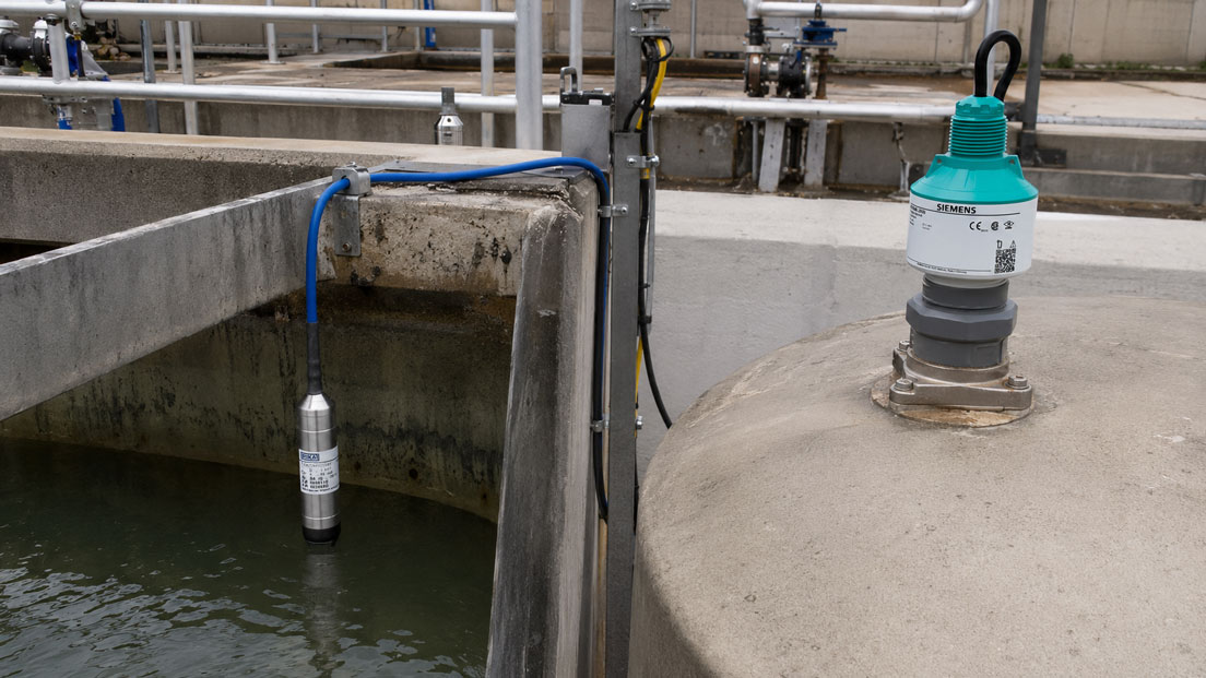
Different measuring principles are available for continuous level measurement in tanks, vessels, shafts and basins. One particularly common question is whether a hydrostatic submersible probe or a non-contact radar level sensor is better suited to the application.
Both measuring methods can provide a reliable level value for a PLC, control system, display or pump control. However, they measure the level in completely different ways. The submersible probe measures the hydrostatic pressure of the liquid column. A radar sensor, by contrast, measures the distance between the sensor and the product surface from above.
These differences have a direct impact on suitability. Hydrostatic measurement is comparatively simple and robust, but it reacts to changes in liquid density and, in closed vessels, also to additional gas pressure above the medium. Radar measures largely independently of density and vessel pressure, but requires a suitable installation position, a sufficiently reflective product surface and a plausible echo curve.
Foam, condensation, agitators, inlet streams, deposits, aggressive media and changing process conditions can also influence the selection. One measuring principle is therefore not fundamentally better than the other. The decisive factor is which physical measured variable can be recorded most reliably under the actual conditions in the tank.
This article compares hydrostatic submersible probes and radar level sensors, explains typical sources of error and shows which information is required for a reliable instrument selection.
Table of contents
- Why the measuring principle must suit the application
- How a hydrostatic submersible probe measures the level
- How a radar level sensor works
- Direct comparison of submersible probe and radar
- Which principle is suitable for open tanks and basins?
- Level measurement in closed and pressurised tanks
- Why changes in density influence hydrostatic measurement
- Assessing foam, condensation and vapour correctly
- Aggressive, contaminated and abrasive media
- The correct installation position in the tank
- Designing the measuring range, dead zone and tank geometry
- From level to tank volume
- 4–20 mA, HART and PLC connection
- Commissioning and plausibility checking
- When another measuring principle is more suitable
- Typical selection errors
- Practical example: Fluctuating density in a chemical tank
- Practical decision guide
- Which measuring instruments / products are suitable?
- Conclusion
- Frequently asked questions about submersible probes and radar level sensors
Why the measuring principle must suit the application
A level sensor only provides a reliable measured value if its measuring principle suits the medium, vessel and operating conditions. The measuring range alone is not sufficient for selection. Two sensors with a measuring range of 0 to 5 m can react completely differently under identical tank conditions.
A submersible probe determines the level from the pressure exerted by the liquid column on the measuring diaphragm. The sensor therefore requires direct contact with the medium. If the density of the liquid changes, the measured pressure also changes, even if the actual filling height remains the same.
A radar sensor is usually installed above the product surface. It transmits electromagnetic signals towards the medium and evaluates the reflection. A distance is measured first. The level is then calculated from the known tank height.
Radar therefore does not react directly to the mass or density of the liquid. However, the transmitted signal must reach the product surface reliably and return from it with sufficient strength. Internal fittings, unsuitable nozzles, strongly absorbing foam or incorrect sensor alignment can make evaluation more difficult.
Before selecting a product, it should therefore first be clarified which process variable is actually required. If the geometric height of the liquid surface is to be measured, radar is often advantageous. If the level in a simple open water basin is to be monitored, a hydrostatic submersible probe may be the more economical and equally reliable solution.
How a hydrostatic submersible probe measures the level
A hydrostatic submersible probe is a specially sealed pressure transmitter that is lowered directly into the liquid. The measuring diaphragm is positioned as close as possible to the lowest relevant measuring point in the tank. There it measures the pressure of the liquid column above it.
The hydrostatic pressure can be described in simplified form using the following relationship:
p = ρ × g × h
Here, p represents hydrostatic pressure, ρ the density of the liquid, g gravitational acceleration and h the height of the liquid column above the sensor.
With water, a liquid column of one metre produces approximately 98 mbar. A five-metre water column therefore produces around 490 mbar. If a submersible probe is designed for 0 to 5 m water column, this pressure range can, for example, be scaled to an output signal of 4 to 20 mA.
In open tanks, submersible probes often operate with gauge pressure. A venting capillary in the connection cable provides the reference to atmospheric pressure. This largely compensates for normal changes in atmospheric pressure.
This capillary must remain dry and open. If moisture enters the cable or the pressure equalisation opening is blocked, the reference pressure may change. This can result in zero-point shifts or slowly drifting level values.
The submersible probe itself, the connection cable, seals and, where applicable, a protective cap remain in permanent contact with the medium. The materials must therefore be suitable not only for the liquid, but also for cleaning agents, temperature, deposits and mechanical stress.
How a radar level sensor works
A radar level sensor transmits electromagnetic waves from above towards the product surface. The medium reflects part of the signal back to the sensor. The distance to the surface is calculated from the signal travel time or, in FMCW systems, from the frequency difference between the transmitted and received signals.
If the sensor knows the distance between its measuring reference point and the tank bottom, it can determine the level from the measured empty distance:
Level = reference height of the tank − measured distance to the surface
Radar therefore measures a geometric distance. Changes in liquid density generally have no direct influence on this distance. A changing gas pressure above the liquid also normally does not alter the measured distance.
With free-space radar, the measuring method operates without a probe extending into the medium. Depending on the design, however, the antenna, process connection or a flush-mounted sensor surface is located inside the tank atmosphere and must be resistant to the process atmosphere, temperature and medium.
Modern radar sensors often operate at high transmission frequencies and with a strongly focused signal. A narrow beam angle makes measurement easier in narrow tanks and between internal fittings. Nevertheless, the measuring beam must be considered during design. Ladders, agitators, heating coils, braces and liquids entering from the side can cause false echoes.
The reflection strength depends, among other things, on the electrical properties of the medium. Water-based liquids typically reflect radar well. For media with a very low dielectric constant or unusual gas phases, a more detailed assessment of the measuring conditions may be required.
Direct comparison of submersible probe and radar
| Criterion | Hydrostatic submersible probe | Radar level sensor |
|---|---|---|
| Measured variable | Pressure of the liquid column | Distance to the product surface |
| Contact with the medium | Sensor and cable permanently immersed in the medium | Free-space measurement, depending on installation without direct liquid contact |
| Dependence on density | Yes | No, not directly |
| Influence of gas pressure in the tank | Must be considered in closed vessels | Distance measurement largely independent of vessel pressure |
| Open water basins and shafts | Very well suited | Also well suited |
| Contact with the medium and corrosion | Materials of sensor and cable are decisive | Fewer wetted components may be possible |
| Foam | Primarily measures the hydrostatic component of the liquid column | Reflection and signal attenuation must be assessed |
| Condensation | Protection of the venting capillary is particularly important | Condensation on the antenna or sensor surface must be considered |
| Internal tank fittings | Usually little influence as long as the probe hangs freely | Measuring beam and potential false echoes must be considered |
| Maintenance access | Probe may have to be removed from the medium | Sensor often accessible from above |
| Typical output signals | 4–20 mA, in some cases HART or additional temperature measurement | 4–20 mA/HART, digital interfaces, in some cases IO-Link or fieldbus |
The table shows that the technology alone does not provide a clear recommendation. In an open well containing clean water, a submersible probe can operate very simply and reliably. In a pressurised chemical tank with varying density, radar may offer significant advantages.
The required measured variable also plays a role. A hydrostatic probe reacts to the mass of the liquid column. A radar sensor reacts to the position of the surface. With constant density, both variables produce comparable results. With variable density, however, they may differ considerably.
Which principle is suitable for open tanks and basins?
Open tanks, wells, stormwater retention basins, pump shafts and water reservoirs are classic applications for hydrostatic submersible probes. The sensor is installed close to the lowest relevant measuring point and connected to the evaluation system via its cable.
With water and other media with largely stable density, converting pressure into filling height is straightforward. The sensor does not require a clear measuring path from above and can also be used in deep or narrow shafts.
In turbulent media, the probe should not be allowed to strike the vessel uncontrollably. A suitable mounting arrangement, additional weight or protective or guide tube can stabilise the measuring point. The measuring diaphragm must not be mechanically loaded or completely covered by deposits.
The probe should not lie directly on the tank bottom. Sludge, sediment or heavy particles may accumulate there. A small distance from the bottom reduces the risk of a blocked or permanently loaded measuring diaphragm. The resulting offset must be taken into account in the scaling.
Radar is also well suited to open tanks and basins. The sensor is installed above the maximum product surface and measures without contact. This is particularly useful if the sensor is not intended to be immersed in the medium or if maintenance work is easier to carry out from above.
However, a suitable mounting point must be available for radar. Inlet streams, agitators or strongly inclined surfaces should preferably not lie directly in the main measuring beam. In narrow shafts, a radar sensor with a tightly focused signal may be advantageous.
Level measurement in closed and pressurised tanks
In an open tank, approximately atmospheric pressure acts on the liquid surface. A vented submersible probe can use this pressure as a reference and essentially measures only the additional pressure of the liquid column.
In a closed or pressurised tank, however, additional gas or vapour pressure exists above the liquid. This pressure is transmitted throughout the liquid and also acts on the measuring diaphragm of the submersible probe.
A simple submersible probe cannot then distinguish which proportion of the measured pressure is caused by the filling height and which proportion is caused by the tank head pressure. If the gas pressure rises while the level remains constant, the probe would indicate a higher level.
Hydrostatic measurement is still possible in a pressurised vessel, but suitable pressure compensation is required. Typical solutions include differential pressure measurement between the tank bottom and gas space or two coordinated pressure measuring points whose values are offset against each other in the control system.
If the density also changes, the density dependence remains. Simply compensating for gas pressure therefore does not automatically eliminate all measurement deviations.
A radar sensor directly measures the distance to the surface. A changing head pressure does not directly influence this geometric distance. Radar is therefore often a technically straightforward solution for pressurised vessels, provided that the process connection, antenna, seal, pressure rating and temperature range are suitable for the application.
Nevertheless, not just any radar sensor may be used for high pressures, high temperatures, vacuum or an aggressive gas phase. The permissible process data of the specific instrument must be checked completely.
Why changes in density influence hydrostatic measurement
Hydrostatic measurement is based directly on the density of the liquid. If the sensor is scaled for a specific density and this density changes later, the calculated level also changes.
For example, a tank contains a liquid column 5 m high. With water at a density of approximately 1,000 kg/m³, around 490 mbar of hydrostatic pressure is produced. If the medium at the same filling height has a density of only 850 kg/m³, the pressure is only approximately 417 mbar.
If the measurement continues to be evaluated as though the medium were water, 417 mbar corresponds to only approximately 4.25 m of water column. Although the tank is actually filled to 5 m, the system would indicate a level approximately 15 percent too low.
| Filling height | Example density | Hydrostatic pressure | Indication when scaled for water |
|---|---|---|---|
| 5.00 m | 1,000 kg/m³ | approx. 490 mbar | approx. 5.00 m |
| 5.00 m | 950 kg/m³ | approx. 466 mbar | approx. 4.75 m |
| 5.00 m | 850 kg/m³ | approx. 417 mbar | approx. 4.25 m |
Changes in density can be caused by temperature, concentration, mixing ratio, product changes or chemical reactions. With water, the changes are small in many standard applications. With oils, fuels, solvents, alkalis or mixed products, they can be considerably more relevant.
If the density is known and largely constant, the submersible probe can be scaled accordingly. If the density depends on temperature, additional temperature measurement and density compensation may be useful where high accuracy is required.
If the composition of the medium changes unpredictably, hydrostatic level measurement may not be the best choice. Radar measures the surface and is therefore largely independent of such density changes when determining the geometric filling height.
Assessing foam, condensation and vapour correctly
Foam formation is often used as a general argument for or against a measuring principle. However, the first question is which surface or condition is actually to be measured.
A submersible probe is located below the liquid surface. Because of its low density, light foam contributes very little to the hydrostatic pressure. The probe therefore primarily measures the liquid column and not necessarily the top edge of the foam layer.
This can be an advantage if the actual liquid content is required and the foam is to be ignored. If the top of the foam layer must instead be detected as an overfill limit, hydrostatic measurement alone may not be sufficient.
With radar, the behaviour depends on the structure, thickness, moisture content and electrical properties of the foam. Some foams are largely penetrated, while others reflect or significantly attenuate the radar signal. The sensor may then detect the foam surface, the liquid underneath it or temporarily fail to obtain a clearly evaluable echo.
The statement that “radar always measures through foam” is therefore just as inaccurate as the statement that radar never works with foam. In critical applications, the medium, foam properties and required measuring surface should be coordinated with the instrument manufacturer or investigated in a practical test.
Condensation and vapour can also have different effects. With a submersible probe, vapour above the surface usually affects the actual hydrostatic measurement only through the vessel pressure. It is important, however, to prevent condensate from entering the venting capillary or cable connection.
Radar sensors are often more robust than acoustic ultrasonic systems with regard to vapour and temperature changes. Nevertheless, heavy condensation or deposits directly on the antenna or sensor surface can affect signal quality. A suitable antenna design, flush installation or a structural drip edge may be useful in such applications.
Aggressive, contaminated and abrasive media
With a submersible probe, the housing, measuring diaphragm, cable sheath, cable seal and any elastomers are permanently exposed to the medium. The material assessment must therefore not be limited to the metallic sensor body.
A stainless-steel housing may be suitable for a liquid while a standard PUR or PE cable is attacked. Conversely, a chemically resistant cable may be required even though the measuring diaphragm has no special requirements.
Temperature also influences media compatibility. A material that appears suitable at room temperature may age considerably faster at a higher process temperature. For a binding selection, the concentration, temperature, exposure duration and any cleaning media must be considered.
In wastewater, sludge or media containing solids, deposits may form on the measuring diaphragm. The submersible probe should have a diaphragm geometry that is as robust and accessible as possible. Mechanical cleaning must not damage the thin measuring diaphragm.
Abrasive particles and strong flows can place long-term stress on the housing and cable. The probe should therefore not be installed directly in an inlet stream or immediately next to a pump.
Radar reduces direct contact with the medium. Depending on the sensor type and tank material, measurement through the vessel wall may even be possible with plastic tanks. This eliminates the need for a process connection in direct contact with the liquid.
In a metallic or pressurised tank, the radar sensor is usually installed using a nozzle or flange. The process connection, antenna and seal may still come into contact with vapour, splashes or condensation. Material compatibility must therefore also be checked for non-contact measurement.
The correct installation position in the tank
The installation position has a major influence on measurement quality with both principles. A correctly selected technology can become unreliable if installed in an unsuitable position.
Positioning a submersible probe correctly
The submersible probe should hang close to the lowest relevant measuring point, but not directly on the tank bottom or within a sediment layer. The distance from the bottom is taken into account during zero-point and range adjustment.
The cable requires suitable strain relief. It must not be routed over sharp edges, crushed or bent beyond the permissible radius. The pressure equalisation capillary must terminate in a dry area and be protected against moisture.
The probe may swing in the presence of turbulence, flow or large tank diameters. A guide or additional weight can stabilise its position. However, the arrangement must not exert pressure on the diaphragm or encourage deposits.
The probe should not be installed directly below an inlet. The dynamic pressure of the incoming medium can overlap the hydrostatic measured value and cause fluctuating indications.
Positioning a radar sensor correctly
A radar sensor should be installed so that the measuring beam reaches the product surface as unobstructed as possible. Internal fittings such as ladders, pipes, agitators, heating coils and braces should not be located within the central beam.
Installation directly above an inlet is usually unsuitable. The sensor may detect the liquid jet or severe turbulence as an additional reflection. A mounting point offset to the side is often more suitable.
The tank nozzle must suit the antenna. A nozzle that is too long, too narrow or uneven internally can produce unwanted reflections. The antenna must not be recessed uncontrollably inside a metallic nozzle unless the design is intended for this purpose.
With domed or conical tank roofs, the sensor must be aligned as vertically as possible towards the relevant surface. Incorrect inclination can direct the reflected signal away from the sensor.
After installation, many instruments allow false-echo suppression or tank mapping to be performed. This identifies fixed reflections from internal fittings and takes them into account during subsequent measurement. However, this function cannot compensate for a fundamentally unsuitable installation position.
Designing the measuring range, dead zone and tank geometry
The required measuring range is not determined solely by the total tank height. The lowest and highest level, the sensor position and operational safety distances are also decisive.
With a submersible probe, the pressure range is determined from the maximum liquid column above the measuring diaphragm and the density of the medium. If the probe is positioned 20 cm above the tank bottom, this section cannot be recorded as part of the usable measuring range without an appropriate correction.
The selected pressure range should suit the actual application. A sensor designed for 100 m water column may generally provide a signal in a tank with a filling height of only 2 m, but it uses only a small part of its measuring span. This reduces the usable resolution and accuracy of the overall measurement.
With radar, a distinction is made between the measuring reference point at the sensor, the maximum level and the tank bottom. Depending on the instrument, there may be an upper near or dead zone directly below the antenna in which reliable measurement is not possible.
The maximum level must therefore not approach the sensor arbitrarily closely. Deposits, splashing or flooding must also be considered during design. Certain sensors can detect or withstand temporary flooding, but this must be expressly suitable for the specific instrument version.
At the lower end of the range, it must be checked whether the tank bottom produces a stronger echo than a very shallow liquid layer. The tank geometry, medium and instrument settings influence how far the usable measuring range actually extends.
From level to tank volume
Both a submersible probe and radar initially provide a level or a derived filling height. The volume is only calculated from the vessel geometry.
In a vertical cylindrical tank with a constant cross-section, the relationship between height and volume is linear. A filling height of 50 percent then corresponds approximately to 50 percent of the usable volume.
In a horizontal cylindrical tank, the relationship is not linear. Half the filling height does correspond to half the total volume, but other height values cannot be converted using a simple percentage calculation. Tanks with a conical bottom, domed ends or several vessel sections are even more complex.
Linearisation can be carried out in the sensor, an evaluation instrument, the PLC or the control system. Tank dimensions, characteristic curves or a support-point table are stored for this purpose.
A correct level measurement can still result in an incorrect volume value if the tank geometry has been parameterised incorrectly. During commissioning, the electrical raw value, calculated filling height and resulting volume should therefore be checked separately.
4–20 mA, HART and PLC connection
Hydrostatic submersible probes and radar level sensors are frequently available as two-wire transmitters with a 4–20 mA output. In this case, 4 mA usually represents the lower and 20 mA the upper configured measured value.
However, the assignment must always be checked against the parameter settings. In certain applications, the characteristic may be inverted so that a high level corresponds to a lower current value. Under-range and over-range values as well as fault currents must also match the PLC configuration.
Depending on the instrument, additional information can be transmitted via HART or other digital interfaces. This may include the measured distance, calculated level, sensor temperature, signal status or diagnostic messages.
When connecting to a PLC, at least the following points must be checked:
- Output signal of the sensor
- Passive or active analogue input
- Supply voltage and permissible load resistance
- Lower and upper range value
- Unit of the transmitted variable
- Fault current and diagnostic behaviour
- Damping and filtering
- Scaling to filling height or volume
With linear 4–20 mA scaling, an output of 12 mA corresponds to 50 percent of the configured measuring span. Whether this represents 2 m, 5,000 litres or 50 percent tank content depends on the sensor parameterisation and downstream scaling.
The UPS4E loop calibrator can be used for electrical testing of the current loop. It can, for example, measure the loop current or simulate defined 4–20 mA values to check the PLC input.
However, the UPS4E tests neither the hydrostatic pressure nor the radar echo. A correct PLC indication with a simulated 12 mA merely confirms the electrical signal processing from the injection point onwards. The physical function of the level sensor must be tested separately.
Commissioning and plausibility checking
Before commissioning, the tank dimensions, installation position and required measuring range must be documented unambiguously. With a radar instrument, the distance to the zero point, upper filling level and possible false echoes are parameterised in particular.
With a submersible probe, the difference in height between the sensor and tank bottom, the density of the medium and the pressure range must be considered. The venting capillary must remain open and the electrical connection must not absorb moisture.
An initial plausibility check should preferably be carried out at a known level. The actual level can, for example, be determined using a sight glass, dipstick, known filling operation or another independent reference.
With radar, the echo curve should also be examined. A plausible numerical value alone does not prove that the sensor is actually detecting the product surface. A fixed internal fitting, the tank bottom or an agitator may instead be evaluated as the useful signal.
With a submersible probe, it should be checked whether the measured value changes uniformly as the level increases. A constant offset may be caused by the installation height, an incorrect density assumption or an impaired pressure reference.
Where possible, the test should cover several points of the measuring range. The lower operating range, typical working level and upper alarm range are particularly important.
After maintenance work or sensor replacement, the complete scaling must be checked again. A replacement sensor with the same 4–20 mA output may have a different pressure or distance range and can therefore provide incorrect level values despite correct wiring.
When another measuring principle is more suitable
The decision does not always have to be between a submersible probe and free-space radar. Certain applications can be solved more reliably using another method.
Guided-wave radar or TDR measurement guides the radar signal along a rod or cable probe. This principle may be advantageous in narrow vessels, with low dielectric constants, for interface measurement or in difficult tank geometries. However, the probe is in direct contact with the medium and may be affected by heavy deposits or mechanical stress.
Ultrasonic measurement also operates without contact from above. The method may be economical for open water and wastewater applications. However, temperature gradients, vapour, strong air movement and foam may influence sound propagation more strongly than a radar signal.
Depending on their design, capacitive sensors are suitable for continuous measurement or point level detection. Their function depends on the electrical properties of the medium and the construction of the probe. Careful design is required with changing products or heavy deposits.
Magnetostrictive level sensors use a float and can achieve high accuracy. A mechanically suitable float must be available that matches the density and media compatibility requirements.
For pure overfill or dry-run protection functions, a separate point level switch may be useful or required on the basis of the risk assessment. Continuous level measurement does not automatically replace an independent safety device.
Typical selection errors
| Error | Possible consequence | Better approach |
|---|---|---|
| Selection based only on tank height | Measuring principle does not suit the medium or process | Consider density, pressure, temperature, foam and internal fittings |
| Submersible probe scaled for water although the density differs | Systematic error in filling height and volume | Specify the actual operating density and assess fluctuations |
| Submersible probe installed in a pressurised tank | Head pressure is incorrectly interpreted as additional level | Consider differential pressure measurement or a suitable radar principle |
| Radar installed directly above the inlet | Unstable echoes and fluctuating measured values | Select a mounting point outside the inlet stream |
| Radar sensor installed in an unsuitable nozzle | False reflections and restricted near-range measurement | Coordinate nozzle length, diameter and antenna design |
| Foam generally ignored | Sensor measures a different surface than expected | Define whether the liquid or foam surface is required |
| Cable material of the submersible probe not checked | Swelling, embrittlement or liquid ingress | Assess the sensor, cable and seals together |
| 4–20 mA signal adopted without verification | Incorrect PLC scaling despite a functioning sensor | Document and simulate the 4 mA and 20 mA assignments |
Another common error is the expectation that a manufacturer or supplier can select a suitable sensor based solely on the statement “tank height 5 m”. Considerably more information is required for a reliable design.
This includes the medium, density, temperature, tank pressure, geometry, process connection, foam formation, condensation, internal fittings, required output signal and necessary accuracy. For aggressive media, the concentration and material requirements are additionally required.
Practical example: Fluctuating density in a chemical tank
A liquid in an open storage tank is monitored using a hydrostatic submersible probe. The tank is 4 m high and the submersible probe was originally designed for a medium with a density of 1,000 kg/m³.
During operation, however, the tank is alternately filled with mixtures of different concentrations. The density varies between approximately 850 and 1,050 kg/m³. The product temperature also changes depending on production and ambient conditions.
The operating personnel notice that the PLC indicates a significantly different level after a product change, although the quantity filled is almost the same. Electrical testing of the 4–20 mA signal reveals no abnormalities. The submersible probe also responds reproducibly to pressure changes.
The cause is not a defect, but the measuring principle. At a lower density, the same filling height generates a lower hydrostatic pressure. The PLC, which is scaled for a fixed density, interprets this pressure as a lower level.
One possible solution would be to store the current density for each product in the controller. However, this requires the composition and density to be known reliably for every filling operation. Additional uncertainty remains during mixing phases and temperature changes.
Since the actual geometric filling height is decisive for the application, a radar level sensor is considered. It measures the distance to the surface independently of the changing product density. The clear measuring path in the tank, reflection properties of the media and resistance of the process connection are checked before selection.
After correct installation outside the inlet stream, the measurement is compared with an independent reference at several levels. The indication now remains plausible even after product changes.
The example shows that a functioning sensor can nevertheless use the wrong measuring principle for the required process variable. The submersible probe had measured the hydrostatic pressure correctly. What was required, however, was a density-independent measurement of the geometric filling height.
Practical decision guide
A hydrostatic submersible probe is often a good choice when an open tank, well, shaft or basin containing liquid is to be monitored and the density of the medium is known and sufficiently stable.
It is particularly suitable when no appropriate mounting point is available above the tank, internal fittings make a clear radar path difficult or the measuring point is deep and narrow. Hydrostatic measurement can also be advantageous with heavy surface foam if the liquid column below the foam is specifically required.
Radar is often the better choice when the density changes, direct contact with the medium is undesirable or a closed or pressurised tank is to be monitored. Non-contact measurement may also offer advantages where maintenance access, hygiene or product changes are important.
The following guidance does not replace an application assessment, but shows typical tendencies:
| Application | Generally suitable principle | Reason |
|---|---|---|
| Open water tank with constant density | Submersible probe or radar | Both principles are generally suitable |
| Deep well or narrow shaft | Submersible probe | Simple installation directly in the medium |
| Pressurised process vessel | Radar or differential pressure measurement | A simple submersible probe is affected by head pressure |
| Medium with strongly fluctuating density | Radar | Geometric distance measurement is not directly dependent on density |
| Heavy foam, with the liquid surface below the foam being relevant | Submersible probe or application-tested radar | The required measuring surface must be defined clearly |
| Aggressive liquid where sensor contact is undesirable | Radar | Fewer components in contact with the medium may be possible |
| Tank with many internal fittings and very limited clear space | Submersible probe or strongly focused radar | Installation position and measuring beam are decisive |
| Sludge basin with sediment on the bottom | Radar or protected submersible probe | Deposits on the submersible probe must be considered |
Which measuring instruments / products are suitable?
The level sensors, level transmitters and submersible probes category contains different solutions for continuous measurement in tanks, shafts, wells and vessels.
Hydrostatic submersible probes are particularly suitable for open tanks, water and wastewater applications, wells, pump shafts and liquids with a sufficiently known density. Depending on the application, different pressure ranges, housing and cable materials, accuracy classes, explosion-protected versions and output signals are available.
When selecting a submersible probe, the density and temperature of the medium, cable material, required cable length, installation height, venting, sediment and possible turbulence must be specified in addition to the maximum filling height.
Radar and FMCW level sensors are suitable for non-contact distance and level measurement. They can be particularly advantageous when the product density changes, the tank is pressurised or direct contact between the sensor and liquid is to be avoided.
For radar, the tank height, maximum and minimum level, nozzle dimensions, vessel geometry, internal fittings, medium, foam formation, condensation, pressure and temperature must be assessed. The electrical properties of the medium and required antenna design may also be relevant.
The higher-level level measurement technology category additionally includes other measuring principles and components for continuous level measurement, point level detection and signal evaluation.
For instruments with a 4–20 mA output, the UPS4E loop calibrator is suitable as a supplementary instrument for electrical commissioning and troubleshooting. It can be used to test the loop current, PLC input and scaling or simulate defined current values.
However, the UPS4E does not replace a hydrostatic pressure reference or a test of the radar echo. It only evaluates the electrical current loop. For a complete measuring-chain test, the physical level measurement must also be checked using a suitable reference.
ICS Schneider Messtechnik assists with selecting the measuring principle and with the technical design. To provide a reliable recommendation, the most complete possible information about the tank, medium, operating conditions, installation point, measuring range and required signal connection should be supplied.
Conclusion: The application, not the sensor price, determines the right choice
Submersible probes and radar level sensors can both provide reliable measured values. However, they detect different physical variables. The submersible probe measures the pressure of the liquid column, while radar determines the distance to the product surface.
A hydrostatic submersible probe is often a simple and economical solution for open tanks, wells and shafts containing liquids of known density. Radar often offers significant advantages with changing density, closed pressurised vessels or undesirable contact with the medium.
Nevertheless, radar is not automatically suitable for every tank. The measuring beam, nozzle, internal fittings, foam formation, condensation and reflection properties must be assessed. Conversely, a submersible probe is not unsuitable simply because foam or a difficult vessel design is present.
The best solution is determined by the medium, tank geometry, pressure, temperature, density, installation position and required measured variable. Collecting this information carefully before product selection prevents incorrect measurements, unnecessary sensor replacements and costly subsequent modifications.
Frequently asked questions about submersible probes and radar level sensors
What is the most important difference between a submersible probe and radar?
The submersible probe measures the hydrostatic pressure of the liquid column. Radar measures the distance between the sensor and product surface. The submersible probe is therefore dependent on density, while radar records the geometric filling height largely independently of density.
Which solution is better for an open water tank?
Both a submersible probe and radar may be suitable. A submersible probe is often particularly simple and economical. Radar offers advantages when non-contact measurement, good access from above or low maintenance requirements are desired.
Can a submersible probe be used in a closed pressurised tank?
A simple hydrostatic submersible probe is additionally influenced by the gas pressure above the liquid. Suitable pressure compensation, differential pressure measurement or another measuring principle is therefore required for a pressurised tank.
Why does density influence the measured value of a submersible probe?
Hydrostatic pressure is determined by density, gravitational acceleration and liquid height. A denser liquid produces a higher pressure at the same height than a lighter liquid.
Is radar completely independent of the medium?
No. Although distance measurement is not directly dependent on density, the strength and quality of the reflected radar signal depend, among other things, on the electrical properties of the medium, the surface and the process conditions.
Does radar work with foam?
This depends on the type, thickness and moisture content of the foam. Radar may penetrate the foam, reflect from its surface or be strongly attenuated by it. Critical applications should be assessed individually.
Does a submersible probe measure the height of foam?
Light foam produces only a small hydrostatic pressure. The submersible probe therefore primarily measures the liquid column underneath and not necessarily the top of the foam layer.
Can condensation interfere with a radar sensor?
Heavy condensation or deposits on the antenna can affect signal quality. Modern radar sensors are often robust under such conditions, but the antenna design and installation position must still suit the application.
Why does a submersible probe require a venting capillary?
With gauge-pressure measurement, the capillary provides the reference to atmospheric pressure. This compensates for normal changes in atmospheric pressure. The capillary must remain dry and open.
What happens if water enters the venting capillary?
The pressure reference may be impaired. This can cause zero-point shifts, slow drift or implausible level values. The cable termination and connection area must therefore be protected against moisture.
May a submersible probe lie directly on the tank bottom?
This is generally not recommended. Sediment may cover or mechanically load the measuring diaphragm. The probe should be installed with a defined distance from the bottom.
Can the submersible probe be suspended from its cable?
Many submersible probes are designed for this installation method. Nevertheless, the manufacturer’s specifications, permissible tensile load and suitable strain relief must be observed. The cable must not be routed over sharp edges.
Where should a radar sensor be installed?
It should be aligned as vertically as possible towards the product surface and installed away from inlet streams. Fixed internal fittings should not be located within the central measuring beam.
Can radar measure through a plastic tank?
Depending on the tank material, wall thickness and sensor, measurement through a non-conductive plastic wall may be possible. This must be checked for the specific instrument version and vessel construction.
Can radar measure through a metal tank?
No. Metal reflects the radar signal. The sensor therefore requires a suitable process connection or opening into the tank interior.
What does dead zone mean with a radar sensor?
The dead or near zone is an area directly in front of the antenna in which reliable distance measurement is not possible. The maximum permissible level must remain outside this area.
How is the measuring range of a submersible probe determined?
The required pressure range is determined from the maximum liquid height above the probe and the density of the medium. Possible overloads and the installation height above the tank bottom must also be considered.
How is volume calculated from the level?
The measured level is converted into volume using the tank geometry. A characteristic curve or support-point table is required for non-linear vessel shapes.
Can a sensor output both level and volume?
Depending on the instrument, tank linearisation may be stored directly in the sensor. Alternatively, conversion is carried out in an evaluation instrument, PLC or control system.
Which output signal is commonly used for a PLC?
4–20 mA is very common, often supplemented by HART communication. Depending on the instrument, digital interfaces, IO-Link or fieldbus protocols may also be available.
How can a 4–20 mA level signal be tested?
A loop calibrator can measure the actual loop current or simulate a defined current value for the PLC input. This allows the wiring and scaling to be tested.
Can the UPS4E fully calibrate the level sensor?
No. The UPS4E tests the electrical 4–20 mA signal chain. For a complete test, a defined hydrostatic pressure must be generated for a submersible probe and a known reference distance or defined level for radar.
When is guided-wave radar more suitable than free-space radar?
Guided-wave radar may be advantageous in narrow vessels, for interface measurement or with media that produce weak radar reflections. However, the rod or cable probe is in direct contact with the medium.
Do I additionally require a point level switch?
This depends on the application, risk assessment and applicable requirements. Independent point level detection may be useful or required for overfill or dry-run protection.
Which information is required for selection?
At minimum, the medium, density, temperature, tank pressure, tank height, geometry, process connection, internal fittings, foam formation, condensation, required measuring range, output signal, accuracy and possible explosion-protection or safety requirements are needed.