


Analogue voltage signals from 0 to 10 V are still widely used in mechanical engineering, building automation, HVAC systems and control cabinet construction. They transmit, for example, setpoints for frequency converters, control commands for valve actuators, measured values from pressure, temperature or humidity sensors, as well as position and level information to a PLC, controller or display.
When an implausible measured value occurs, the question quickly arises in practice as to whether the sensor, wiring, power supply, analogue input or simply the scaling in the PLC program is faulty. A suitable process signal calibrator can be used to apply a defined 0–10 V signal directly to the analogue input. This allows the entire processing chain to be checked, from the connection in the control cabinet through to the display in the control system.
The test is fundamentally straightforward, but it requires a clear understanding of the signal principle. A voltage signal always requires a common reference potential. Input impedance, cable resistance, potential differences, grounding and loads connected in parallel also influence the measured value. A 0–10 V signal must therefore not be treated like a 4–20 mA current loop.
This article explains how to simulate a 0–10 V signal correctly, the differences between 0–10 V and 2–10 V, how to check PLC scaling and how to systematically narrow down typical faults in the control cabinet.
Table of contents
- How a 0–10 V signal works
- Where 0–10 V signals are used
- What does simulating 0–10 V mean?
- Why the reference potential is crucial
- Input impedance and loading of the signal source
- Distinguishing correctly between 0–10 V and 2–10 V
- 0–10 V and 4–20 mA compared
- Do not confuse the sensor supply with the output signal
- Test procedure for a PLC analogue input
- Checking PLC scaling correctly
- Testing 0–10 V transmitters
- Testing displays, controllers and frequency converters
- Typical faults in 0–10 V signals
- Shielding, grounding and cable routing
- Practical example: PLC displays an incorrect value despite 5 V
- Documenting test results effectively
- Which measuring instruments / products are suitable?
- Conclusion
- Frequently asked questions about simulating 0–10 V signals
How a 0–10 V signal works
With a 0–10 V signal, the measuring or control range is represented by a DC voltage. 0 V usually corresponds to the lower end of the range and 10 V to the upper end. With linear scaling, a signal of 5 V represents 50 percent of the configured range.
For example, a pressure sensor with a measuring range of 0 to 10 bar can output 0 V at 0 bar and 10 V at 10 bar. At 5 V, the PLC should then display approximately 5 bar. A control valve with a 0–10 V input could correspondingly move to 50 percent of the defined control range at 5 V.
The voltage signal is always measured between two conductors: the signal output and the associated reference potential. Depending on the manufacturer, this reference potential may be designated GND, COM, M, 0 V, analogue ground or signal ground. Without a correct connection to the reference potential, the receiver cannot evaluate the signal voltage unambiguously.
The output signal must not be confused with the sensor supply voltage. A 0–10 V sensor is often supplied separately with 24 V DC and provides the analogue output signal at another terminal. This is typically a three-wire or four-wire connection.
The exact terminal assignment must always be taken from the data sheet of the sensor or transmitter. Identical conductor colours or terminal designations must not be assumed across different devices.
Where 0–10 V signals are used
Voltage signals are used particularly frequently within machines, control cabinets and buildings. In these applications, cable lengths are usually limited and the environmental conditions can be managed through suitable cable routing and grounding.
Typical applications include setpoint signals for frequency converters, speed controllers and power controllers. Valve actuators, damper actuators, heating controllers and building automation components also frequently use 0–10 V or 2–10 V.
Transmitters for temperature, pressure, air quality, humidity, level, position or differential pressure may also have a voltage output. The PLC processes the signal through an analogue input card and converts the voltage into the actual process variable.
A 0–10 V signal can either transmit a measured value or provide a setpoint. This initially makes no difference to the electrical test. However, the operational effect can be considerable: While a simulated sensor signal may only change a display, a simulated setpoint signal can control a motor, valve or another machine function.
Before simulation, it must therefore be clarified exactly which response the connected system may trigger. It may be necessary to disconnect drives, inhibit enable signals or place the controller in a safe test mode.
What does simulating 0–10 V mean?
When simulating a 0–10 V signal, a calibrator generates a defined DC voltage and feeds it into the analogue input in place of the original sensor or setpoint generator. The calibrator temporarily assumes the function of the signal source.
For the test, the sensor is normally electrically disconnected from the input. The positive output of the calibrator is then connected to the signal input and the negative output to the associated reference potential.
Several defined voltage values are then set. At minimum, the lower value, midpoint and upper value should be tested. For a more detailed test, 25 and 75 percent points can also be used.
| Test point | Signal for 0–10 V | Expected proportion of the measuring range |
|---|---|---|
| Lower range point | 0.00 V | 0% |
| 25 percent point | 2.50 V | 25% |
| Range midpoint | 5.00 V | 50% |
| 75 percent point | 7.50 V | 75% |
| Upper range point | 10.00 V | 100% |
If the display and the PLC raw value are correct at all points, the analogue input, including its scaling, is fundamentally plausible. If the display already deviates with a calibrator signal applied directly, the fault is not in the disconnected sensor, but probably in the input, the wiring between the test point and the input, or the software configuration.
Simulation does not replace a complete calibration of the original sensor. It initially tests the electrical signal chain from the injection point onwards. To assess the complete measuring chain, the actual physical variable must also be generated at the sensor and measured using a suitable reference.
Why the reference potential is crucial
A voltage value always exists between two electrical potentials. An analogue input can only measure 5 V correctly if both the signal and the associated reference potential are connected.
Depending on the input card, a PLC may have common ground connections for several channels or separate reference potentials for individual channels or channel groups. If the wrong terminals are used, the signal may be too low, too high, unstable or completely absent.
Potential differences between the sensor supply, PLC ground and grounded system components are particularly critical. A sensor may correctly output 5 V relative to its local ground, while a different value is present at the PLC input due to a shifted reference potential.
During troubleshooting, the voltage should therefore not only be measured directly at the sensor, but also between the signal input and the actual reference terminal of the analogue input. Only this value corresponds to the voltage that the PLC actually processes.
Depending on its design, a process signal calibrator may be galvanically isolated from other circuits or may acquire a reference through connected equipment. Before making the connection, it must be checked whether unwanted ground or earth connections could be created. This is particularly important when a power supply, PC, oscilloscope or grounded measuring instrument is connected at the same time.
Input impedance and loading of the signal source
A voltage output can only supply a limited current. The input of the connected device must therefore have a sufficiently high impedance. The lower the input impedance, the higher the current that the signal source must provide at the same voltage.
The relationship follows Ohm’s law:
I = U / R
With an input resistance of 100 kΩ, for example, only 0.1 mA flows at 10 V. With 10 kΩ, the current is already 1 mA. If several inputs are connected in parallel, the total resistance decreases and the required output power increases.
If the signal source cannot provide the required current, the output voltage collapses. The calibrator may display a set value of 10 V while only 8 or 9 V is actually present at the connected input.
The C.A 1631 is designed to output DC voltage up to 20 V. A maximum output current must be observed for the voltage output. Before testing, it should therefore be checked whether the input impedance of the analogue input and any displays, controllers or data loggers connected in parallel are compatible with the output capability of the calibrator.
If several receivers are connected in parallel, each input should preferably be tested individually. This makes it possible to determine whether a particular device is loading the signal line too heavily or whether the overall circuit is outside the permissible output load.
Distinguishing correctly between 0–10 V and 2–10 V
0–10 V and 2–10 V use the same maximum voltage but have different lower range points. With 0–10 V, 0 V corresponds to the start of the measuring range. With 2–10 V, 2 V usually corresponds to the lower end and 10 V to the upper end of the range.
| Test point | 0–10 V | 2–10 V |
|---|---|---|
| 0% | 0.00 V | 2.00 V |
| 25% | 2.50 V | 4.00 V |
| 50% | 5.00 V | 6.00 V |
| 75% | 7.50 V | 8.00 V |
| 100% | 10.00 V | 10.00 V |
The elevated zero point of a 2–10 V signal can be used for plausibility monitoring. A value significantly below 2 V may indicate a missing supply, an open circuit or a faulty output. Whether the controller actually recognises such a condition as a fault depends on the programming and configuration of the analogue input.
If a 2–10 V transmitter is incorrectly scaled as 0–10 V, the PLC will already display 20 percent at 2 V. Conversely, a PLC configured for 2–10 V may produce negative, limited or faulty values when receiving an actual 0–10 V signal.
Before testing, it is therefore not enough to know only the maximum voltage. The complete signal definition is required, including the lower range value, upper range value and associated process variable.
0–10 V and 4–20 mA compared
0–10 V and 4–20 mA are analogue standard signals, but they operate differently electrically. With a voltage signal, the receiver evaluates the voltage between the signal and the reference potential. In a current loop, the current flowing through the entire series circuit is measured.
| Characteristic | 0–10 V | 4–20 mA |
|---|---|---|
| Transmitted variable | DC voltage | DC current |
| Typical connection | Signal and reference potential, frequently with a separate supply | Current loop with components connected in series |
| Lower range value | 0 V or, for example, 2 V | Usually 4 mA |
| Influence of cable resistance | May be relevant with loaded sources and ground shifts | Usually has less influence on the current within the available loop voltage |
| Behaviour in the event of a broken wire | 0 V may also be a valid measured value | 0 mA is clearly below the normal measuring range |
| Parallel connection of receivers | Generally possible, but the load on the source must be considered | Receivers are generally not connected in parallel in the same current loop |
For longer cables, large installations and industrial environments with significant interference, 4–20 mA is often preferred. Within machines, control cabinets and building automation systems, however, 0–10 V remains widespread and technically suitable when the reference potential, cable routing and input impedance are designed correctly.
A common testing error is connecting a current simulator directly to a voltage input or feeding a voltage calibrator into a 4–20 mA loop. The input configuration must therefore be verified clearly before making the connection.
Do not confuse the sensor supply with the output signal
Many 0–10 V transmitters require a separate supply voltage, frequently from the control cabinet’s 24 V DC system. The supply is connected to positive and 0 V. The 0–10 V output signal is available at another terminal relative to the common or separate signal reference.
When testing the analogue input, a calibrator that outputs 0–10 V only replaces the signal output. It does not automatically supply the disconnected transmitter. If the transmitter itself is to be tested, its supply must remain present and correct.
Before taking a measurement, three variables should therefore be considered separately:
- Supply voltage of the transmitter
- Output voltage of the transmitter
- Voltage actually reaching the analogue input
If the supply voltage is absent, a fully functional sensor cannot provide a valid output signal. If a correct signal is present at the sensor but not at the PLC, the fault is probably located in the cable, a terminal, an isolating amplifier, a selector switch or the reference potential.
Some transmitters have galvanically isolated inputs and outputs. Others use a common ground for the supply and signal. The wiring must therefore not be based solely on a general three-wire or four-wire diagram.
Test procedure for a PLC analogue input
Before testing begins, it must be clarified which process responses could be triggered by the simulated signal. Automatic control functions, limit alarms, interlocks and drives must be placed in a safe condition in accordance with the system concept.
The circuit documentation is then used to verify that the input is actually a voltage input. Many PLC input modules can be switched between voltage and current by wiring, jumpers or software. An incorrect configuration can distort the test result or cause an impermissible load.
The original signal source is electrically disconnected from the analogue input. This prevents two active voltage outputs from operating against each other. A calibrator must not simply be connected in parallel with a sensor that remains active.
The positive voltage output of the calibrator is connected to the signal input. The negative output is connected to the reference potential intended for that channel. A low and safe test value is then set first.
After a plausibility check, the defined test points can be applied one after another. For each point, the output voltage, PLC raw value, scaled process value and, where applicable, the display in the control system are documented.
To test linearity, the points should be applied in both ascending and descending order. This allows software limits, filtering or unexpected hysteresis in downstream displays and controllers to be identified.
After completion of the simulation, the calibrator is removed, the original wiring is restored and the system is returned to operation in a controlled manner. Before release, the actual sensor value should be checked for plausibility.
Checking PLC scaling correctly
The analogue input initially converts the applied voltage into a digital raw value. This raw value is then scaled to the physical process variable in the PLC program or module configuration.
A 0–10 V signal may represent, for example, 0 to 100 percent, 0 to 10 bar, −50 to +50 °C or 0 to 2,000 rpm. The electrical voltage alone therefore does not indicate the required engineering unit.
For linear scaling, the expected process value can be calculated in simplified form:
Process value = lower measured value + signal proportion × measuring span
A pressure transmitter with a 0–10 V output and a measuring range of 0 to 16 bar must display approximately 8 bar at 5 V. A temperature sensor with a 0–10 V output for −20 to +80 °C must display approximately +30 °C at 5 V, because the total measuring span is 100 °C.
| Simulated signal | Expected value for 0–16 bar | Expected value for −20 to +80 °C |
|---|---|---|
| 0.00 V | 0 bar | −20 °C |
| 2.50 V | 4 bar | 5 °C |
| 5.00 V | 8 bar | 30 °C |
| 7.50 V | 12 bar | 55 °C |
| 10.00 V | 16 bar | 80 °C |
If the PLC displays exactly the midpoint at 5 V but incorrect values at the endpoints, the upper or lower scaling limits are often entered incorrectly. If the deviation remains constant across the entire range, an offset error may be present.
If the deviation increases proportionally, an incorrect gain factor, unsuitable input type or incorrect measuring span is more likely. Fluctuating raw values, by contrast, tend to indicate contact problems, interference, an unstable reference potential or an unsuitable filter setting.
Testing 0–10 V transmitters
When testing a transmitter, the input and output sides must be considered separately. A temperature transmitter, for example, may accept a Pt100 resistance and generate a 0–10 V output. A pressure transmitter, by contrast, processes a mechanical pressure signal.
The transmitter supply voltage is checked first. The output is then measured to determine whether the expected voltage is present. The voltage must be measured between the signal output and the designated signal reference.
To test the transmitter completely, a known reference variable must be applied to its input. For a temperature transmitter, this may be a resistance or temperature simulator. For a pressure transmitter, a suitable pressure source with a reference pressure measuring instrument is required.
Simulating 0–10 V at the PLC input only tests the downstream processing. It does not confirm that the transmitter correctly converts its input variable into the voltage signal.
Dividing the measuring chain into sections is therefore particularly effective during troubleshooting:
- Check the physical measured variable at the sensor
- Check the output signal directly at the transmitter
- Check the signal at the control cabinet input
- Check the signal directly at the PLC terminal
- Compare the raw value and scaled display
This approach allows the faulty section to be identified much more quickly than replacing individual components as a precaution.
Testing displays, controllers and frequency converters
In addition to PLC analogue inputs, digital displays, process controllers, position controllers and frequency converters can also be tested with a defined voltage signal. The relevant input must actually be configured for 0–10 V or the required voltage range.
With a digital display, the test checks whether the electrical input voltage is converted correctly into the configured display range. With a controller, it is also possible to check whether limits, relay outputs and control parameters respond at the intended input values.
On a frequency converter, a simulated voltage signal can change the set frequency or speed. Special safety measures are required. The motor may only be controlled if the test setup, machine and hazardous area permit it.
Many frequency converters also provide an internal 10 V auxiliary supply for a setpoint potentiometer. This terminal is a supply output and must not be confused with the analogue input. The calibrator is connected to the actual voltage input and its reference terminal.
Connecting the calibrator output directly to an external 10 V supply can connect two active voltage sources against each other. The terminal designations and circuit must therefore be clarified unambiguously before testing.
Typical faults in 0–10 V signals
Faults in a voltage signal chain can often be narrowed down by their behaviour. A permanent 0 V signal may be caused by a missing sensor output, an interrupted signal cable, a missing supply or an unconnected reference potential.
A measured value that is too low may indicate an overloaded signal source, several inputs connected in parallel, input resistance that is too low or a voltage drop caused by unsuitable connections. Incorrect 2–10 V or 0–10 V scaling is also possible.
| Fault pattern | Possible cause | Recommended test |
|---|---|---|
| PLC permanently displays 0 | Interrupted signal, sensor without supply, missing reference potential | Measure the supply, signal and COM connection separately |
| Signal is significantly too low | Source overloaded, input resistance too low, parallel loads | Compare the voltage without load and under load |
| Signal fluctuates significantly | Loose terminal, EMC interference, unstable ground, unsuitable filtering | Check terminals, cable routing, shielding and the raw value |
| Display starts at 20% | 2–10 V signal scaled as 0–10 V | Compare the signal definition of the transmitter and PLC |
| Midpoint is correct, endpoints are incorrect | Incorrect scaling limits or limiting function | Check the raw value and software parameters |
| Signal is correct at the sensor but not at the PLC | Cable fault, incorrect reference potential, isolating amplifier or terminal | Measure the voltage section by section along the signal chain |
| Calibrator does not reach 10 V | Output load too high or two sources connected in parallel | Connect receivers individually and completely disconnect the sensor |
If a correct calibrator signal is applied to the PLC input but an incorrect raw value is still displayed, the input type, channel configuration and module diagnostics should be checked. Some cards have different terminals for current and voltage inputs or require software selection of the measuring range.
If the PLC value remains unchanged at different simulated voltages, the wrong channel may be monitored, the input card may be disabled or a substitute value function may be active. Software filters, manual operating values or overwritten variables must also be considered.
Shielding, grounding and cable routing
0–10 V signals should be routed separately from motor cables, frequency converter outputs, contactor coils and other cables with high interference levels. Parallel routing over long distances can induce interference voltages.
Shielded, twisted-pair cables are frequently used for sensitive analogue signals. How the shield is connected depends on the system concept, cable length, frequency range of the interference and equipotential bonding situation.
A general statement that the shield must always be connected at one end only or always at both ends is not correct for every installation. The component manufacturers’ requirements and the machine’s EMC and grounding concept are decisive.
The signal shield is not automatically the electrical return conductor of the 0–10 V signal. The reference potential must be carried through the designated conductor. If the shield is used as the signal ground, interference currents and equipotential bonding currents may influence the measured value.
Poorly executed terminal connections can also be problematic. Contact resistances alone generally cause only small static voltage drops with high-impedance inputs, but corrosion, vibration or intermittent contacts can cause fluctuating measured values.
Practical example: PLC displays an incorrect value despite 5 V
In a ventilation system, a differential pressure transmitter provides a 0–10 V signal for a measuring range of 0 to 500 Pa. The building management system permanently displays approximately 150 Pa, although a handheld measuring instrument indicates a significantly higher differential pressure.
The transmitter supply is checked first. A stable 24 V DC is present between the supply terminals. Directly at the signal output of the transmitter, 5.0 V is measured relative to its 0 V terminal. With linear scaling, this should correspond to approximately 250 Pa.
Approximately 5.0 V is also measured at the PLC terminal. The sensor supply, output and cable therefore initially appear plausible. The display of 150 Pa cannot be explained by a simple voltage drop.
The transmitter is disconnected from the analogue input and a process signal calibrator is connected. At 0 V, the PLC displays 0 Pa; at 5 V, approximately 150 Pa; and at 10 V, approximately 300 Pa. The electrical processing is linear but clearly uses an incorrect upper scaling limit.
A measuring range of 0 to 300 Pa is stored in the PLC configuration. During a previous replacement, the transmitter had been exchanged for a 0 to 500 Pa version without adapting the software parameters.
After correction, the PLC displays approximately 250 Pa at 5 V and 500 Pa at 10 V. The actual transmitter is then reconnected and the display is checked under operating conditions.
The example shows that an apparently incorrect sensor value is not necessarily caused by a defective sensor. Simulating defined voltage values separates the sensor side from the PLC processing and makes scaling errors immediately visible.
Documenting test results effectively
Traceable documentation should not merely state that the analogue input “works”. It is useful to record the tested channel, signal range, associated measuring range, calibrator used and the individual test points.
For each test point, the target voltage, actual output voltage, PLC raw value, displayed process value and permissible deviation can be documented. For safety-related or quality-relevant applications, the date, technician, device identification and calibration status of the reference instrument should also be recorded.
If only part of the measuring chain is tested, this should be stated clearly. Electrical simulation at the PLC input is not a complete calibration of the sensor and does not confirm the mechanical or physical measuring point.
For recurring tests, identical test points help to identify changes over time. Noticeable deviations can then be assigned to an analogue input, transmitter or cable connection at an early stage.
Which measuring instruments / products are suitable?
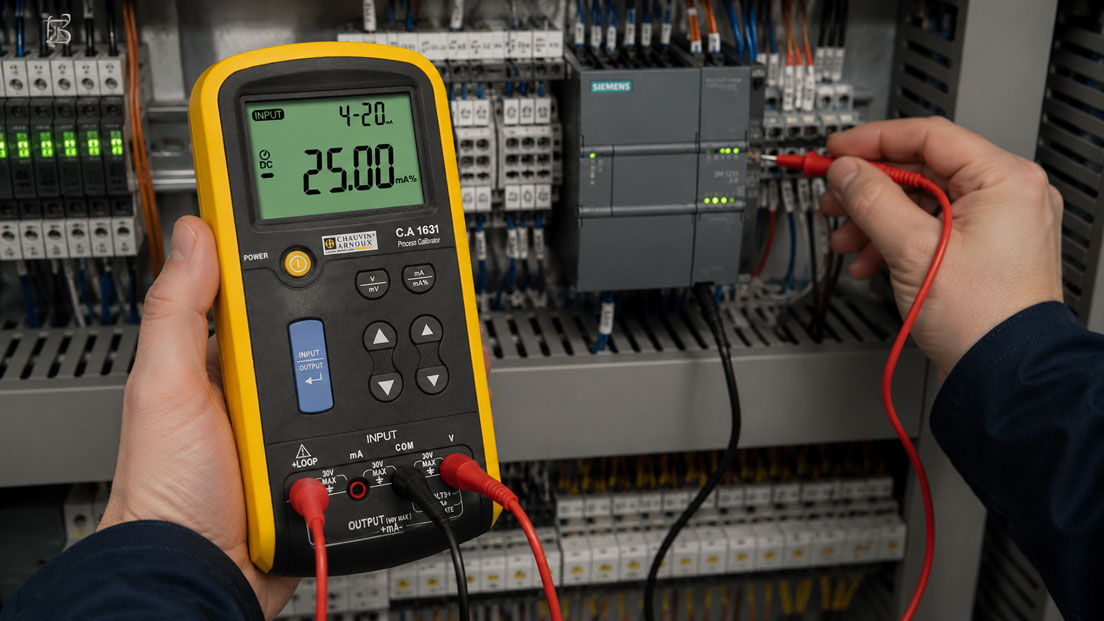
The C.A 1631 process signal calibrator is suitable for simulating 0–10 V, 2–10 V and other analogue voltage signals. The instrument can measure and output DC voltages, allowing it to be used both to simulate a voltage signal and to check existing sensor signals.
With its voltage range up to 20 V, the C.A 1631 covers typical signals such as 0–10 V, 2–10 V, 0–5 V and 1–5 V. For testing, the calibrator is connected directly to the analogue input in place of the sensor.
The permissible load on the calibrator must be considered when outputting voltage. Particularly with low input impedances, receivers connected in parallel or faulty wiring, the actual output voltage may deviate from the set value. Suitability should therefore be checked using the input data of the connected equipment.
The C.A 1631 can also measure and output current signals. It is therefore suitable for service tasks involving both 0–10 V and 4–20 mA signals. The correct operating mode must be selected before each connection, because voltage and current signals are connected differently.
Additional instruments for generating and testing electrical process signals can be found in the simulators category. Depending on the application, resistance thermometers, thermocouples, frequency, pulses and other sensor signals can also be simulated in addition to voltage and current.
For applications focused exclusively on 4–20 mA current loops, the UPS4E loop calibrator may be a suitable alternative or addition. It is designed for current loops, transmitter power supply and loop checks.
However, the UPS4E is not the primary instrument for simulating 0–10 V signals. A process calibrator such as the C.A 1631 is required for a genuine voltage output.
ICS Schneider Messtechnik assists with selecting the appropriate calibrator based on the required signal types, voltage and current ranges, accuracy requirements, input loads and planned test task.
Conclusion: A defined voltage signal allows the cause of the fault to be narrowed down quickly
A 0–10 V signal can be simulated directly at the analogue input using a suitable process signal calibrator. This makes it possible to check whether a PLC, display, controller or frequency converter measures and scales the specified voltage value correctly.
For a reliable test, the signal and reference potential must be connected correctly. The input impedance, output capability of the signal source, sensor supply and possible parallel loads must also be considered.
0–10 V must not be confused with 2–10 V or 4–20 mA. An incorrect definition of the lower range point alone can cause significant scaling errors even though the sensor and analogue input are electrically fault-free.
The C.A 1631 is particularly suitable for servicing, commissioning and troubleshooting because it can measure and output both DC voltage and current signals. This allows different analogue interfaces in the control cabinet to be checked using one compact process calibrator.
However, the simulation only tests the section of the measuring chain from the injection point onwards. For a complete assessment, the original sensor or transmitter must also be tested with the actual physical input variable.
Frequently asked questions about simulating 0–10 V signals
How can I simulate a 0–10 V signal?
The original signal source is disconnected from the analogue input. A process signal calibrator is then connected with its positive output to the signal input and its negative output to the associated reference potential. Defined voltage values between 0 and 10 V are then generated.
Which voltage values should I use for the test?
At minimum, 0 V, 5 V and 10 V should be tested. For a more detailed multipoint test, 2.5 V and 7.5 V are also useful. For 2–10 V signals, the corresponding points are 2 V, 4 V, 6 V, 8 V and 10 V.
Can I connect the calibrator in parallel with the sensor?
This is not permissible with two active voltage outputs. The sensor and calibrator could operate against each other. For simulation, the sensor should normally be disconnected completely from the analogue input.
Why does a 0–10 V signal require a reference potential?
A voltage is always measured between two points. In addition to the signal conductor, the analogue input therefore requires a defined reference terminal such as COM, M or 0 V.
Is 0 V always a fault?
No. With a genuine 0–10 V signal, 0 V can be a valid lower measured value. At the same time, 0 V may also result from a broken wire or missing sensor supply. Without additional diagnostics, the two conditions cannot always be distinguished.
What is the difference between 0–10 V and 2–10 V?
With 0–10 V, 0 V corresponds to the lower end of the range. With 2–10 V, the lower range value is 2 V. The PLC scaling must match the output characteristic of the signal source exactly.
Why does a 2–10 V sensor already display 20 percent at 2 V?
In this case, the input is probably incorrectly scaled as 0–10 V. With correct 2–10 V scaling, 2 V must correspond to a process value of 0 percent.
Can a multimeter simulate a 0–10 V signal?
A conventional multimeter can usually only measure voltage, not output it as a precisely adjustable process signal. A voltage or process signal calibrator is required for simulation.
Can I use a laboratory power supply as a 0–10 V simulator?
Technically, a suitably configured laboratory power supply can provide a voltage. However, a calibrator is usually more suitable for process signal work because it is finely adjustable, portable and designed for corresponding test tasks. The ground reference, current limit and possible overvoltages of a laboratory power supply require particular attention.
Why does the calibrator not reach 10 V under load?
The connected input may have an excessively low impedance or several loads may be connected in parallel. Incorrect wiring or an active sensor that is still connected can also load the output voltage.
What does input impedance mean?
Input impedance describes how strongly the analogue input electrically loads the signal source. A high input impedance requires only a small current and is generally advantageous for a voltage signal.
Can I supply several analogue inputs with one 0–10 V signal?
A parallel connection may be possible if all inputs use the same reference potential and the signal source can supply the resulting total current. The input impedances and manufacturer specifications must be checked.
How do I check whether the sensor or PLC is faulty?
First, the sensor signal is measured directly. The sensor is then disconnected from the input and a defined calibrator signal is applied. If the PLC responds correctly, the fault is probably on the sensor side. If it responds incorrectly, the input, wiring or scaling must be investigated.
How do I test a 0–10 V transmitter completely?
A known physical or electrical reference variable must be generated at the transmitter input while the output signal is measured. Simulating the signal only at the PLC input does not test the transmitter itself.
Why is the signal correct at the sensor but not at the PLC?
Possible causes include an interrupted cable, poor terminal connection, incorrect reference potential, an intermediate isolating amplifier or loading by other connected devices.
Can a potential difference change the measured value?
Yes. If the sensor and PLC have different reference potentials, the voltage actually measured at the input may shift. The measurement should therefore be taken directly between the signal input and the associated COM terminal.
Does the cable shield have to be connected to 0 V?
Not automatically. The shield is used to suppress interference and is not inherently the signal return conductor. It must be connected in accordance with the EMC and grounding concept and the manufacturer’s specifications.
How can I identify incorrect PLC scaling?
The scaling can be checked using defined test points. With 0–10 V, 5 V must correspond exactly to the midpoint of the programmed process span. If the raw value and voltage are correct but the displayed process value is not, a scaling error is likely.
Can I also simulate 2–10 V with the C.A 1631?
Yes. Since the C.A 1631 can output DC voltages up to 20 V, 2–10 V, 1–5 V and other typical voltage signals can also be generated.
Can the C.A 1631 also test 4–20 mA?
Yes. In addition to DC voltage, the instrument can measure and output process currents. However, the correct operating mode must be selected before connection and the circuit must be configured for the current signal.
Is the UPS4E suitable for 0–10 V signals?
The UPS4E is primarily designed for 4–20 mA current loops. A process signal calibrator such as the C.A 1631 is more suitable for generating a genuine 0–10 V voltage signal.
Can the simulation cause a machine to start?
Yes. If the voltage signal is processed as a setpoint or enable signal, the simulation can activate drives, valves or other functions. The system must therefore be placed in a safe condition before testing.
What information is required when selecting a signal calibrator?
Important information includes the required signal types, voltage and current ranges, required measuring and output accuracy, necessary output load capability, type of connected inputs and additional functions such as loop power supply or percentage display.