


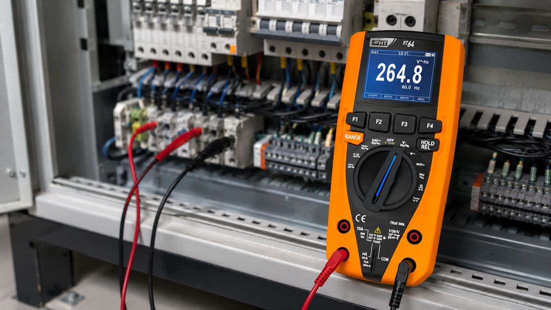
A digital multimeter is one of the most important measuring instruments in electrical service, maintenance and control cabinet construction. It is used to check voltages, inspect circuits, measure resistances, evaluate fuses, test continuity or narrow down fault signals. Especially in the control cabinet, however, a multimeter is only helpful if measuring function, connection, measuring range, test leads and safety category match the task.
Many measurement errors are not caused by a defective measuring instrument, but by incorrect use. Typical causes include an incorrectly connected test lead, the wrong socket, current measurement in parallel with the voltage source, continuity testing on a live conductor, unsuitable test leads, an incorrect CAT category or a misunderstanding between voltage, current and resistance.
This article explains how multimeters are used correctly in control cabinets, which measurement errors occur particularly often and why work on electrical systems may only be carried out by qualified personnel. The focus is on socket selection, voltage measurement, current measurement, continuity testing, test leads, fuses, CAT category, phantom voltages, LoZ function, TRMS measurement and correct interpretation of the measurement results.
Table of contents
- Safety first: work only by qualified personnel
- Basics: what a multimeter can do in the control cabinet
- Socket selection and measuring function: the most common user error
- Measuring voltage correctly: always in parallel with the measuring point
- Measuring current correctly: in series, with the correct socket or with a current clamp
- Continuity, resistance and diode testing only when voltage-free
- CAT category, test leads and device protection
- Correctly classifying TRMS, LoZ and phantom voltages
- Typical measurement errors in the control cabinet
- Practical example: fuse appears to be OK, but the system still does not run
- Which measuring instruments / products are suitable?
- Conclusion: a multimeter is only as safe as its use
- FAQ: frequently asked questions about multimeters in control cabinets
Safety first: work only by qualified personnel
Measurements in control cabinets can be dangerous. Mains voltages, control voltages, high short-circuit capacities, stored energy, frequency converters, power supplies, capacitors and sensitive electronic components are often present there. An incorrect measurement can not only damage the multimeter, but also cause arcs, short circuits, system damage or personal injury.
For this reason, work on electrical systems and control cabinets may only be carried out by qualified personnel. This includes knowing the system, being able to assess the hazards, using suitable personal protective equipment, understanding the measurement category of the measuring instrument and complying with the relevant safety rules. A multimeter does not replace electrical qualification.
Before every measurement, it should be clear what is to be measured: voltage, current, resistance, continuity, frequency, diode path or an analog signal. The question of where the measurement is being taken is just as important: on the mains side, in the control circuit, at a PLC terminal, at a frequency converter, at a power supply or at a sensor. Depending on the measuring location, the risk and the requirements for measuring instrument and test leads differ significantly.
Safe working starts before the measuring instrument is even switched on. Test leads must be undamaged, plugs must be firmly seated, the correct socket must be selected and the measuring range must match the task. In addition, if the measurement is safety-relevant, the multimeter should be checked for proper function on a known source before and after a voltage test.
| Situation | Typical risk | What to pay particular attention to? |
|---|---|---|
| Measurement on mains voltage in the control cabinet | Electric shock, arc flash, short circuit | Use suitable CAT category, intact test leads and correct measuring function. |
| Measurement on frequency converters | Non-clean signal waveforms, high interference components, stored energy | Observe TRMS measurement, safe discharge and manufacturer specifications. |
| Current measurement with multimeter | Short circuit due to incorrect parallel measurement | Measure only in series and via the correct current socket. |
| Continuity test | Damage to the measuring instrument when voltage is present | Measure only when voltage-free and safely verify absence of voltage beforehand. |
| Measurement in tight terminal fields | Slipping of the test probe, short circuit between adjacent terminals | Use suitable probe tips, caps and calm handling. |
Basics: what a multimeter can do in the control cabinet
A digital multimeter can measure various electrical quantities. In the control cabinet, AC voltage, DC voltage, DC current, AC current, resistance, continuity, frequency and sometimes temperature or capacitance are particularly relevant. Modern TRMS multimeters can also measure non-sinusoidal AC quantities more accurately than simple average-responding instruments.
In the control cabinet, a multimeter is frequently used for troubleshooting. It helps, for example, to check whether a supply voltage is present, whether a power supply delivers 24 V DC, whether a fuse has continuity, whether a relay contact switches, whether a coil receives voltage or whether a sensor provides a plausible signal. However, the multimeter always only shows what is actually detected at the selected measuring point and with the selected measuring function.
An important point is the distinction between measuring and testing. A multimeter can display a voltage, but it is not always the best instrument for safely verifying absence of voltage. For safety-relevant voltage tests, two-pole voltage testers are often used. The multimeter is particularly strong in diagnostics, troubleshooting, signal evaluation and electrical comparative measurements.
Correct interpretation is just as important as the measured value itself. A displayed voltage does not automatically mean that the source can supply load current. A continuity indication does not automatically mean that a contact works reliably under load. A measured resistance says little if other components are connected in parallel in the circuit. The measurement result must therefore always be evaluated in the context of the circuit diagram and the system.
Socket selection and measuring function: the most common user error
Correct socket selection is one of the most important requirements for safe measurement. Many multimeters have separate sockets for voltage/resistance and current. If a test lead is accidentally left in the current socket and a voltage measurement is then performed, the multimeter can create almost a short circuit through the internal current measurement path. This can trip fuses in the measuring instrument or, in unfavorable cases, become dangerous.
Before every measurement, it should therefore be checked whether the test leads are inserted into the correct sockets. For voltage, resistance and continuity measurements, the COM socket and the V/Ω socket are usually used. For current measurements, a mA, µA or 10 A socket must be used depending on the current level. Which socket is permissible depends on the device and the expected current.
The rotary switch or function selector must also match the measuring task. Measuring DC voltage on AC voltage may not provide a meaningful value. Measuring resistance in a live circuit can damage the instrument. Measuring current in the wrong range can trip the internal fuse.
A good workflow is therefore: determine the measuring task, select the measuring function, connect the test leads correctly, check the measuring range, place the probes safely and only then evaluate the measured value. After a current measurement, the test leads should deliberately be moved back to the voltage/resistance socket so that no dangerous error occurs during the next voltage measurement.
| Measuring function | Typical socket | Connection method | Common error |
|---|---|---|---|
| Voltage AC/DC | COM and V | In parallel with the measuring point | Test lead is still in the current socket. |
| Resistance | COM and Ω | On the voltage-free component or circuit | Resistance is measured while voltage is present. |
| Continuity | COM and Ω / continuity | Only when voltage-free | Continuity test in an active control circuit. |
| Current mA / A | COM and mA or A | In series with the load | Multimeter is connected in parallel with the voltage source. |
| Frequency | COM and V / Hz | Depending on the signal, in parallel or at the signal output | Signal level or measuring range does not match the input function. |
Measuring voltage correctly: always in parallel with the measuring point
Voltage measurement is performed in parallel with the measuring point. This means: the multimeter is not inserted into the circuit, but measures the potential difference between two points. Typical measurements in the control cabinet are L to N, L to PE, N to PE, 24 V DC to 0 V, output of a power supply, voltage at a coil or voltage at a PLC input.
With DC voltage, polarity must also be observed. If the red test lead is held to the more negative point and the black test lead to the more positive point, the multimeter usually displays a negative value. This is not necessarily an error, but indicates reversed polarity. In the control cabinet, however, incorrect polarity can indicate wiring errors, incorrectly labeled terminals or a reversed supply.
With AC voltage, it is important whether the multimeter measures the true RMS value. In modern control cabinets, non-sinusoidal voltages or interference often occur due to frequency converters, switching power supplies and pulsed loads. A simple multimeter can evaluate such signals incorrectly. In many cases, a TRMS multimeter is the better choice here.
Voltage measurements must also be interpreted in terms of load capability. A high-impedance digital multimeter can also display capacitively coupled or so-called phantom voltages. This voltage looks real on the display, but can collapse under load. In such cases, a LoZ function or a suitable two-pole voltage tester can help to better assess the situation.
Measuring current correctly: in series, with the correct socket or with a current clamp
Current measurement is one of the most error-prone multimeter applications. Unlike voltage, current is not measured in parallel, but in series with the load. This means the circuit must be opened and the multimeter inserted into the current path. The entire current then flows through the measuring instrument and its internal fuse.
If a multimeter in the current range is accidentally connected in parallel with a voltage source, a very low-resistance path is created. This can trip the internal device fuse, switch off a system fuse or have dangerous consequences in the case of high short-circuit capacity. This error is one of the classic reasons for damaged multimeters and hazardous situations in control cabinets.
Before a current measurement, the expected current must be known or at least roughly estimated. If the current may be above the permissible range, measurement must not be started directly in the small mA range. Many multimeters have separate fused ranges for mA and A. After a current measurement, the lead should immediately be removed from the current socket again.
In many control cabinet applications, a current clamp or clamp adapter is the safer and more practical solution. The circuit then does not have to be opened. For high load currents, motor supply cables or hard-to-access conductors, this is often much more sensible than direct current measurement with the multimeter. With small process signals or current loops, however, it must be checked whether the resolution and accuracy of the current clamp are sufficient.
Continuity, resistance and diode testing only when voltage-free
Continuity testing and resistance measurement may only be performed on voltage-free circuits. For these measuring functions, the multimeter applies a small test voltage itself and evaluates the resulting current. If external voltage is present, the measurement result may be incorrect or the measuring instrument may be damaged.
In the control cabinet, continuity testing is frequently used to roughly check fuses, switches, relay contacts, terminal connections, wires or protective conductor connections. Important: an acoustic continuity indication only shows that a low-resistance path is present. It does not automatically indicate whether the contact works reliably under load or whether the connection is permanently load-bearing.
Resistance measurements in installed condition can be distorted by parallel components. A coil, resistor or sensor may be connected to other components in the circuit. The multimeter then does not only measure the component, but the entire connected path. For a clear measurement, a component sometimes has to be disconnected or the circuit diagram must be taken into account.
Diode tests on electronic components should also be carried out with caution. In control systems, frequency converters or PLC modules, internal protective circuits, capacitors and semiconductors can influence the result. Such measurements should only be performed if it is clear what is being tested and which test voltage the multimeter uses in this function.
CAT category, test leads and device protection
The measurement category is decisive when working in the control cabinet. It describes the environment and possible overvoltages for which a measuring instrument is designed. A multimeter with an unsuitable category can become dangerous in the event of transient overvoltages or high short-circuit capacity, even if the displayed nominal voltage appears to fit.
In control cabinets, CAT III or CAT IV requirements are often relevant, depending on the measuring point and system. CAT III typically concerns measurements in fixed installations, distribution boards and industrial systems. CAT IV concerns measurements at the source of the low-voltage installation, for example at the supply point or in areas with particularly high transient energies. The exact classification must be made by qualified personnel based on the system.
Test leads must match the measurement category of the multimeter. A high-quality multimeter loses its safety advantage if unsuitable, damaged or non-matching test leads are used. Insulation damage, loose plugs, broken tips or missing protective caps are particularly critical in the control cabinet.
The internal fuses of the multimeter are also important. Current ranges must be protected by suitable high-energy fuses. If a fuse has blown, it must not be replaced by just any fuse. Voltage, breaking capacity, design and manufacturer specifications must match. An incorrect fuse can massively reduce device protection.
| Safety aspect | Importance in the control cabinet | Typical error |
|---|---|---|
| CAT category | Protection against transient overvoltages and high energies | Measuring instrument with too low a category is used in the distribution board. |
| Test leads | Part of the safety concept, not just accessories | Damaged or unsuitable leads continue to be used. |
| Probe tips | Prevent accidental short circuits between terminals | Too long exposed tips in tight terminal fields. |
| Device fuses | Protect current ranges in the event of incorrect use | Incorrect replacement fuse with unsuitable breaking capacity. |
| Device condition | Damage can influence safety and measured value | Multimeter with cracks, defective socket or loose contact is used. |
Correctly classifying TRMS, LoZ and phantom voltages
TRMS stands for True Root Mean Square, meaning true RMS measurement. This is particularly important when AC voltages or AC currents are not sinusoidal. In modern control cabinets, nonlinear loads, frequency converters, switching power supplies and pulsed loads are common. This can create waveforms that simple multimeters do not measure correctly.
With such waveforms, a TRMS multimeter usually provides significantly more reliable values than a simple average-responding instrument. However, this does not mean that every display is automatically interpreted correctly. With frequency converters, pulsed outputs or strongly disturbed signals, the measuring function, frequency range and manufacturer specifications of the multimeter must be observed.
LoZ refers to voltage measurement with low input impedance. Normal digital multimeters are very high-impedance. This is good for many measurements, but can result in capacitively coupled phantom voltages being displayed. The LoZ function loads the measuring point more strongly and can help determine whether a voltage is actually load-capable or only appears due to coupling.
Phantom voltages frequently occur in long cables, unconnected wires, cables routed in parallel or open PLC inputs. A high-impedance multimeter may then display a voltage even though there is no energy-rich circuit behind it. Nevertheless, such measurement results must be evaluated carefully. An apparent phantom voltage must never be dismissed as harmless without technical assessment.
Typical measurement errors in the control cabinet
A common error is confusing voltage and current measurement. Voltage is measured in parallel, current in series. Anyone who holds the multimeter in the current range in parallel with a voltage source practically creates a short circuit. This error can also occur if the red test lead is still plugged into the A or mA socket after a previous current measurement.
Another typical error is continuity testing on an active circuit. The beeper of the multimeter must not be used as a quick check in an energized system. Before resistance, continuity or diode measurements, absence of voltage must be established and verified.
Incorrect measuring ranges and incorrect signal types also lead to misinterpretations. DC instead of AC, AC instead of DC, average measurement instead of TRMS, mA instead of A or frequency measurement on an unsuitable signal can generate implausible values. Modern autorange multimeters reduce some errors, but they do not replace correct selection of the measuring function.
Measurement errors also occur due to poor contact. Oxidized terminals, loose probe tips, unstable adapters or insulated test points can make it appear as if voltage is not present. In tight control cabinets, the test probe can also slip and short adjacent terminals. Suitable probe tips and terminal adapters increase safety here.
| Error | Typical cause | Possible consequence |
|---|---|---|
| Voltage measured with lead in current socket | Test lead not moved after current measurement | Short circuit, tripped fuse, device damage. |
| Current measured in parallel | Current measurement principle misunderstood | Dangerous short circuit through the multimeter. |
| Continuity checked while voltage is present | Absence of voltage not verified | Incorrect measured value or damaged measuring instrument. |
| Phantom voltage interpreted as real supply | High-impedance measurement on coupled conductor | Troubleshooting goes in the wrong direction. |
| Unsuitable CAT category used | Measuring location and energy of the system underestimated | Increased risk in case of overvoltages or incorrect measurement. |
Practical example: fuse appears to be OK, but the system still does not run
In a control cabinet, a 24 V DC control voltage for part of the system fails. The maintenance technician first measures at the output of the power supply and obtains 24 V DC. The fuse is then measured. Against 0 V, the multimeter also shows 24 V on both sides of the fuse. The fuse is therefore initially assessed as OK.
In the next step, the measurement is considered under load. At the load, the voltage only arrives briefly and then collapses. It also turns out that there is a loose contact at one terminal. Without load, the voltage appeared to be present with the high-impedance multimeter, but under real load the circuit could not supply sufficient current.
Troubleshooting shows: a voltage measurement alone does not always indicate whether a supply can deliver load current. In such cases, measuring point, load condition, terminals, fuse holder, contact resistance and cable routing must be considered together. A continuity test would only be permissible when voltage-free and must not be carried out in the active state.
The example shows why multimeter measurements in control cabinets must always be evaluated with an understanding of the circuit. A single measured value can be correct and still lead to the wrong conclusion if measuring function, load condition and circuit diagram are not considered together.
Which measuring instruments / products are suitable?
For measurements in the control cabinet, the category digital multimeters is a useful starting point. There you will find multimeters for electrical service, maintenance and diagnostic tasks where voltage, current, resistance, continuity, frequency or other electrical quantities need to be checked.
The HT64 TRMS digital multimeter is particularly interesting for demanding control cabinet and service tasks. It offers TrueRMS measurement, a high measurement category, AC/DC voltage and current measurement, resistance and continuity testing, frequency measurement, diode test, LoZ input, bargraph, data logger function and other functions for troubleshooting.
If not only classic multimeter measurements but also current loops and analog process signals need to be checked in the control cabinet, the UPS4E loop calibrator can also be useful. Especially with 4–20 mA signals, a specialized loop calibrator is often more practical than a pure multimeter test because mA signals can be measured and simulated in a targeted way.
For safety-relevant voltage tests, it should also be checked whether a two-pole voltage tester is required in addition to the multimeter. A multimeter is very versatile, but it is not the best test instrument in every situation. The selection should always match the task, the system, the measurement category and the qualification of the person carrying out the work.
| Product / area | Typical use | Particularly relevant for |
|---|---|---|
| Digital multimeters | Universal electrical measurements in service and maintenance | Voltage, current, resistance, continuity, troubleshooting and control cabinet diagnostics |
| HT64 TRMS digital multimeter | Professional multimeter measurements in industrial environments | TRMS, CAT IV, LoZ, data logging, AC/DC measurements and diagnostic tasks |
| Two-pole voltage tester | Safety-oriented voltage testing | Absence of voltage, mains testing, loaded voltage testing and on-site service |
| Current clamp / clamp adapter | Current measurement without opening the circuit | Motor cables, load currents, load circuits and hard-to-access conductors |
| UPS4E loop calibrator | Testing and simulation of 4–20 mA signals | Process signals, PLC scaling, transmitter outputs and commissioning |
Conclusion: a multimeter is only as safe as its use
A digital multimeter is a very versatile and useful measuring instrument in the control cabinet. It can measure voltages, currents, resistances, continuity and other electrical quantities and is therefore an important tool for troubleshooting, maintenance and commissioning. At the same time, many errors occur due to incorrect socket selection, incorrect measuring function, unsuitable test leads or incorrect interpretation.
The most important basic rules are: voltage is measured in parallel, current in series or with a suitable current clamp, continuity and resistance only when voltage-free. Measuring instrument, test leads and CAT category must match the measuring location. TRMS helps with non-sinusoidal signals, LoZ can be useful with phantom voltages, but it does not replace technical assessment.
The most important recommendation is: pause briefly before every measurement and check measuring task, measuring function, socket, measuring range and safety risk. Anyone who uses the multimeter deliberately and evaluates the measured values in the context of the circuit diagram avoids typical errors and increases the safety and informative value of the diagnosis.
FAQ: frequently asked questions about multimeters in control cabinets
Is anyone allowed to measure in the control cabinet with a multimeter?
No. Work on electrical systems and control cabinets may only be carried out by qualified personnel. A multimeter is a measuring instrument, but it does not replace electrical training or a safety assessment of the system.
How do you measure voltage correctly with a multimeter?
Voltage is measured in parallel with the measuring point. The test leads are held to the two points between which the voltage is to be determined, for example L to N or 24 V DC to 0 V.
How do you measure current correctly with a multimeter?
Current is measured in series with the load. To do this, the circuit must be opened and the multimeter inserted into the current path. The correct current socket and suitable measuring range are mandatory.
Why is current measurement with a multimeter more dangerous than voltage measurement?
During current measurement, the multimeter has a very low-resistance measuring path. If it is accidentally connected in parallel with a voltage source, a short circuit can occur. Correct socket selection is therefore particularly important.
What is the most common error with multimeters?
A common error is that the test lead remains in the current socket after a current measurement and a voltage measurement is then performed. This can lead to a short circuit, tripped fuse or device damage.
When may continuity be tested?
Continuity may only be tested on voltage-free circuits. Before continuity testing, absence of voltage must be safely verified. Continuity testing on active circuits can damage the measuring instrument and the system.
Why does my multimeter display voltage even though the conductor is not connected?
This can be due to capacitive coupling or phantom voltage. High-impedance multimeters can display such voltages. A LoZ function or a suitable voltage tester can help to better assess the load capability of the voltage.
What does LoZ mean on a multimeter?
LoZ stands for low input impedance. The multimeter loads the measuring point more strongly than in the normal voltage range. This allows coupled phantom voltages to be better distinguished from load-capable voltages.
What does TRMS mean?
TRMS means true RMS measurement. This function is important for non-sinusoidal AC voltages or AC currents, such as those that can occur with frequency converters, switching power supplies or pulsed loads.
Why is the CAT category important?
The CAT category describes the measuring environment and transient overvoltages for which a measuring instrument is designed. In the control cabinet, high short-circuit capacities and overvoltages can occur. The category must therefore match the measuring location.
Is a multimeter sufficient to verify absence of voltage?
For safety-relevant tests, a suitable two-pole voltage tester is often required. A multimeter can measure voltages, but it is not the appropriate device for verifying absence of voltage in every situation.
Why must test leads be checked?
Test leads are part of the safety concept. Damaged insulation, loose plugs, broken tips or unsuitable CAT categories can be dangerous and falsify measured values.
What happens if the multimeter fuse is defective?
A defective current measuring range can mean that current measurement is no longer possible. The fuse may only be replaced by a suitable fuse with matching breaking capacity, rating and design.
Why is resistance measured only when voltage-free?
The multimeter uses its own test voltage during resistance measurement. If external voltage is present, the measurement result may be incorrect or the device may be damaged.
When is a current clamp better than direct current measurement?
A current clamp is particularly useful for higher load currents, motor cables or when the circuit should not be opened. It increases safety and makes measurements in tight control cabinets easier.
Can a multimeter test 4–20 mA signals?
Many multimeters can measure mA signals. For commissioning, simulation and targeted testing of current loops, however, a specialized loop calibrator such as the UPS4E is often more practical.
What should be checked before every measurement?
Before every measurement, measuring task, measuring function, socket selection, measuring range, condition of the test leads, CAT category and the electrical condition of the system should be checked. Only then should the measured value be evaluated.