


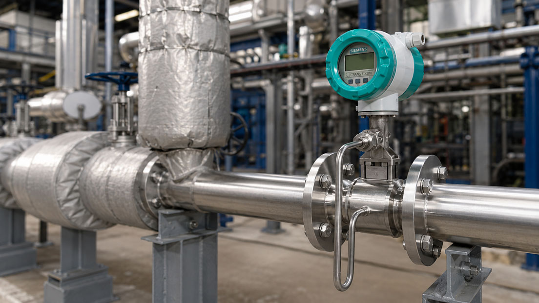
Vortex flow meters, also known as vortex shedding flow meters, are robust measuring instruments for steam, gases and many liquids. They are frequently used in energy plants, chemicals, petrochemicals, the food industry, compressed air systems, steam networks, cooling circuits and general process plants. However, for a vortex device to deliver stable and plausible values, installation location, flow profile, minimum flow, pipework, vibration and process conditions must be carefully matched.
Many measurement errors are not caused by a defective flow meter, but by unfavorable installation conditions. Inlet runs that are too short, pipe bends directly upstream of the device, partially opened valves, pump or compressor pulsations, strong pipe vibration or too low a flow rate can cause the display to fluctuate, show values that are too low or drop out completely at partial load.
This article explains what must be considered when installing vortex flow meters. The focus is on inlet and outlet runs, fittings, pipe bends, pumps, compressors, vibration, pipe supports, minimum flow, pressure loss, installation position, steam insulation, signal evaluation and typical practical errors.
Table of contents
- Basics: how a vortex flow meter works
- Planning inlet runs and outlet runs correctly
- Fittings, pipe bends, reducers and disturbances
- Minimum flow, Reynolds number and stable vortex formation
- Vibration, pulsation and mechanical pipework influences
- Installation position for steam, gases and liquids
- Steam applications: insulation, condensate and energy measurement
- Pressure loss, nominal size and design
- Signal, PLC connection and testing the measurement chain
- Practical example: vortex measured value fluctuates at low load
- Which measuring instruments / products are suitable?
- Conclusion: vortex measurement starts with the right installation situation
- FAQ: frequently asked questions about installing vortex flow meters
Basics: how a vortex flow meter works
A vortex flow meter uses the so-called vortex shedding effect behind a bluff body in the measuring tube. When a medium flows past this bluff body, alternating vortices are formed. The frequency of these vortices has a defined relationship to the flow velocity. The volumetric flow can be calculated from the flow velocity and the pipe cross-section.
The measuring principle is particularly interesting because no moving parts such as turbine wheels or gears are required. This makes vortex devices low-maintenance and robust in many applications. They are especially suitable for steam, gases and liquids when the medium, flow velocity and installation conditions match the measuring principle.
The decisive requirement is stable vortex formation. This only occurs when the flow at the bluff body is sufficiently developed and reproducible. If the flow rate is too low, the flow profile is heavily disturbed or the pipework is mechanically unstable, the vortex signal can fluctuate or become implausible.
| Influencing variable | Why important? | Typical error pattern |
|---|---|---|
| Inlet run | Ensures the most stable possible flow profile upstream of the measuring device | Measured value is systematically too high, too low or fluctuates. |
| Minimum flow | Only sufficient flow produces a stable vortex signal | Display drops out or jumps at partial load. |
| Vibration | Mechanical vibrations can overlay the sensor signal | Measured value indicates flow although little or no flow is present. |
| Pulsation | Pulsating flow disturbs uniform vortex shedding | Measured value fluctuates strongly or follows pump/compressor cycling. |
| Medium condition | Steam quality, gas moisture, condensate or two-phase flow influence the measurement | Unstable or non-reproducible measured values. |
Planning inlet runs and outlet runs correctly
The inlet run is one of the most important points when installing a vortex flow meter. Upstream of the measuring device, the flow should be as uniform as possible. Pipe bends, valves, T-pieces, reducers, expansions, pumps or compressors generate swirl, turbulence and uneven velocity profiles. These disturbances can influence vortex formation at the bluff body.
The specifically required inlet and outlet run depends on the device, nominal pipe size, disturbance and manufacturer specifications. In practice, straight pipe sections upstream and downstream of the measuring device are often required. After strong disturbances, for example after control valves or several pipe bends in different planes, longer calming sections or flow straighteners may be required.
The outlet run is also important. Downstream of the measuring device, the pressure and flow condition should also not be immediately disturbed by a valve, bend or sudden cross-section change. Especially with gases and steam, pressure changes, turbulence and feedback effects on the measuring tube can influence measurement stability.
If there is not enough space in an existing plant, the device should not simply be installed “somewhere”. A technical evaluation is better: Is there a calmer measuring point? Can a valve be moved? Is a flow straightener possible? Is another measuring principle a better fit? A vortex device can only measure as well as the flow at the measuring point allows.
| Disturbance upstream of the vortex device | Possible influence | Practical assessment |
|---|---|---|
| Single pipe bend | Distorted flow profile and slight swirl | Observe straight inlet run according to manufacturer specifications. |
| Two pipe bends in different planes | Stronger swirl and complex flow profile | Particularly critical; check longer calming section. |
| Control valve or partially opened valve | Turbulence, pressure fluctuation and flow separation | Avoid installing directly upstream of the measuring device wherever possible. |
| Pump or compressor | Pulsation, vibration and unstable flow | Check distance, damping and pipe support. |
| Reducer or expansion | Changed velocity and disturbed profile | Consider smooth transitions and sufficient flow stabilization. |
Fittings, pipe bends, reducers and disturbances
Fittings near a vortex flow meter are particularly critical when they strongly change the flow. A fully opened shut-off valve is usually less problematic than a partially opened control valve. Control valves often generate strong turbulence and pressure fluctuations. For this reason, they should generally not be installed directly upstream of the vortex device.
Pipe bends and T-pieces also influence the measurement. After a pipe bend, the flow profile is often no longer symmetrical. Two pipe bends in different planes also generate additional swirl. This swirl can cause vortex shedding at the bluff body to deviate from the ideal condition.
Reducers and expansions can be useful when the measuring nominal size needs to be adapted to the actual flow rate. However, they must be designed properly from a flow engineering perspective. Sudden cross-section changes directly upstream of the measuring device are unfavorable. An incorrectly selected reducer can also increase pressure loss or shift the flow velocity into an unsuitable range.
In existing plants, it is often tempting to install the vortex flow meter wherever space is available. For stable measurement, however, the process should be considered: Where is the flow calm? Where is the pipe completely filled? Where are there no strong vibrations? Where are maintenance, parameterization and electrical connection easily possible?
Minimum flow, Reynolds number and stable vortex formation
A vortex flow meter requires sufficient flow velocity. Below a certain flow rate, no stable, evaluable vortices are formed. The device can then no longer provide a reliable measured value. This behavior is not a defect, but a characteristic of the measuring principle.
The minimum flow depends on medium, density, viscosity, nominal pipe size, pressure, temperature and device design. With gases and steam, operating pressure and operating temperature play an important role because they influence density and flow velocity. With liquids, viscosity is particularly relevant.
A typical selection error is choosing a nominal size that is too large. The device may fit mechanically into the pipe, but in normal operation it works too far down in the measuring range. Especially during partial load, night operation, fluctuating consumption or seasonal load profiles, the minimum flow can be undershot. The display then fluctuates or remains without a stable value at small quantities.
For this reason, not only the maximum flow should be considered during sizing. The typical operating flow and the actual minimum flow are at least equally important. A vortex device should be selected so that it is operated safely above the lower measuring limit in the normal working range.
| Design point | Why important? | Typical consequence of incorrect design |
|---|---|---|
| Minimum flow | Determines whether stable vortices are formed | Measured value drops out at low load. |
| Typical flow | Should be within the stable working range of the device | Device operates permanently close to the lower limit. |
| Maximum flow | Determines pressure loss and mechanical load | Overload, increased flow velocity or unnecessary pressure loss. |
| Medium data | Density and viscosity influence signal formation | Measuring range is incorrectly estimated under real conditions. |
| Nominal size | Determines velocity in the measuring tube | Nominal size too large leads to unstable signal at small quantities. |
Vibration, pulsation and mechanical pipework influences
Vortex flow meters detect a dynamic signal. For this reason, mechanical vibrations and process pulsations can influence the measurement. Strong pipe vibrations, pumps, compressors, pulsating flows or poorly supported pipes can overlay the sensor signal and lead to fluctuating or apparent flow values.
Measuring points directly near piston pumps, compressors, fast-switching valves or vibrating units are particularly critical. Long, poorly supported pipe sections can also vibrate. If the vibration frequency is in an unfavorable range, it can be mistaken for the vortex signal or detected as a disturbance.
Stable pipe support is therefore important. The measuring device should be installed free of mechanical stress, and the pipe should be sufficiently supported upstream and downstream of the device. At the same time, supports must not introduce impermissible mechanical stresses into the measuring device. In the case of strong vibration, it should be checked whether the installation location can be changed, the pipework can be supported better or another measuring principle should be used.
Pulsation differs from pure vibration. With pulsation, the actual flow changes periodically. This can occur with piston pumps, dosing pumps, compressors or cycling valves. The vortex flow meter may then display real fluctuations. Nevertheless, damping, a pulsation damper or another measuring point may be necessary if a stable average value is required.
Installation position for steam, gases and liquids
The correct installation position depends on the medium and process condition. With liquids, it is important that the measuring tube remains completely filled. Air or gas bubbles in the measuring tube can disturb vortex formation. An installation position in which air pockets can collect is therefore unfavorable. With horizontal installation, complete filling and suitable pipe routing should be ensured.
With gases, it must be considered that condensate or liquid content can disturb the measurement. If condensate collects in the measuring tube, the vortex signal can become unstable. The measuring point should be selected so that condensate does not remain in the measuring device and the medium flows through the sensor as single-phase as possible.
With steam, the installation position is particularly important because condensate, wet steam, heat losses and pipe routing interact. Measurement in a pipe with heavy condensate formation or two-phase condition can become unstable. Dry or defined steam condition, suitable drainage and a sensible position in the steam network are decisive.
The manufacturer’s specifications for installation position should always be observed. Depending on the device and application, horizontal, vertical or certain preferred orientations may be recommended. The position of the transmitter, electronics and possible pressure or temperature compensations must also match the installation situation.
Steam applications: insulation, condensate and energy measurement
Vortex flow meters are frequently used for steam because the measuring principle is well suited to many steam and energy applications. With steam, the task is often not only volumetric flow, but mass flow or energy. Pressure and temperature data are important for this because density and enthalpy depend on process conditions.
In steam applications, the pipe often has to be insulated to reduce heat losses and prevent condensate formation. It is important to insulate the measuring device according to the manufacturer’s specifications. Electronics, transmitter housing and certain neck or cooling areas must not be heated beyond permissible limits. Incorrect insulation can lead to electronics problems or shortened service life.
Condensate is another central point. If condensate forms in the measuring tube or directly upstream of the measuring device, the medium condition changes. The vortex flow meter then no longer sees steam only, but a two-phase flow of steam and water content. This can lead to strongly fluctuating or non-reproducible measured values.
For energy or heat quantity measurements, the entire measurement chain must also be considered. Vortex flow meters with pressure and temperature compensation can provide mass flow and energy information. For the values to be correct, however, sensors, parameterization, steam tables, installation location, insulation and control system must match.
Pressure loss, nominal size and design
A vortex flow meter generally causes moderate pressure loss because a bluff body is present in the measuring tube. Pressure loss depends on nominal size, medium, density, velocity and design. In many applications it is uncritical, but it should not be ignored with steam, gases and energy-sensitive processes.
The nominal size should not automatically correspond to the pipe size. The decisive factor is the flow velocity in the measuring tube. If the nominal size is too large, the minimum flow may not be reached. If it is too small, pressure loss and velocity increase. A reducer can be useful if it brings the flow into a stable measuring range, but it must be planned properly.
With gases and steam, conversion between standard volume, operating volume and mass is particularly important. A device that fits well at a certain operating pressure can be in a different working range at another pressure or temperature. For this reason, operating data should always be specified with real minimum, normal and maximum values.
Good sizing therefore considers not only the pipe diameter, but the actual process: medium, condition, pressure, temperature, minimum flow, normal flow, maximum flow, permissible pressure loss, steam quality, installation location and desired measured variable.
Signal, PLC connection and testing the measurement chain
Depending on the version, vortex flow meters provide analog, digital or pulse-based signals. Typical signals are 4–20 mA, HART, pulse/frequency outputs, relay outputs or fieldbus communication. For plant integration, it is decisive that measured variable, unit, measuring range, damping, totalizer and PLC scaling match correctly.
With vortex devices, volumetric flow, standard volumetric flow, mass flow or energy can be output depending on parameterization. It must therefore be clearly documented which process variable is assigned to which output. An electrically correct 4–20 mA signal can still be interpreted incorrectly if the PLC expects a different range or another unit.
The UPS4E loop calibrator is suitable for testing 4–20 mA signals. It can be used to measure and simulate mA signals, test current loops and detect scaling errors between vortex flow meter, transmitter, PLC, display or data logger. This is particularly helpful during commissioning, device replacement, parameter changes or troubleshooting.
With fluctuating measured values, not only the electrical signal should be checked. It must also be investigated whether the fluctuation really comes from the process. This includes inlet runs, flow range, vibration, pulsation, steam dryness, pipe filling and parameterization of damping. Only then can it be reliably assessed whether the error is electrical, mechanical or process-related.
| Check point | Possible error | Effect |
|---|---|---|
| 4–20 mA scaling | Measuring device and PLC use different ranges | Flow is displayed incorrectly although the mA signal is correct. |
| Unit | Confusion between operating volume, standard volume, mass or energy | Values appear implausible or do not match the balance. |
| Damping | Too much or too little signal smoothing | Real changes are hidden or fluctuations appear too strong. |
| Totalizer | Wrong unit, wrong pulse value or reset logic | Total quantity does not match the process balance. |
| Diagnostics | Warnings or signal quality are ignored | Installation or process problems remain undetected. |
Practical example: vortex measured value fluctuates at low load
In a plant, the steam consumption of a production line is monitored with a vortex flow meter. During main production, the measured values are stable and plausible. During partial-load phases in the morning and evening, however, the display fluctuates strongly. At times, the measured value briefly drops to zero, although steam is still being consumed.
Initially, an electrical fault is suspected. The 4–20 mA loop is checked and provides stable signals when defined values are simulated. The PLC scaling is also correct. However, process analysis shows that steam consumption at partial load is very close to the lower measuring range limit of the vortex device.
In addition, a control valve is located relatively close upstream of the measuring device. At small opening degrees, it generates strong turbulence and pressure fluctuations. In combination with low flow, no stable evaluable vortex signal is produced. The device is not defective; rather, the installation situation and the actual partial-load operation do not sufficiently match the measuring task.
After checking the process data, the measuring point is re-evaluated. A more suitable inlet run, a different position for the control valve and a suitable nominal size design are checked. The example shows: fluctuating vortex measured values are often caused by minimum flow, disturbances and flow profile, not by the sensor alone.
Which measuring instruments / products are suitable?
For vortex applications, the SITRANS FX300 vortex flow meter is a suitable solution. It is suitable for steam, gases as well as conductive and non-conductive liquids and is available as a compact or remote version depending on the application. The integrated pressure and temperature compensation is particularly interesting when mass flow, standard volumetric flow or energy information is required.
The category Coriolis / Vortex is the right starting point when vortex and Coriolis measuring principles are to be compared or designed for a specific application. Vortex is particularly strong with steam, gases and many applications requiring robust volumetric or mass flow, while Coriolis offers advantages for direct mass flow measurement and density information.
For the higher-level selection of the correct measuring principle, the category flow measurement technology is also useful. Depending on medium and process, alternatives such as MID, ultrasonic, Coriolis, turbine or other methods can also be considered if vortex is not optimal due to minimum flow, vibration, two-phase flow or installation conditions.
If a vortex flow meter is integrated into a PLC or control system via 4–20 mA, the UPS4E loop calibrator is helpful. It can be used to test and simulate current signals and quickly identify scaling errors in the measurement chain.
| Product / area | Typical use | Particularly relevant for |
|---|---|---|
| SITRANS FX300 vortex flow meter | Vortex flow measurement for steam, gases and liquids | Steam networks, process gases, liquids, energy measurement, standard volume and mass flow |
| Coriolis / Vortex | Selection of Coriolis and vortex flow meters | Principle comparison, sizing, steam, gas and liquid applications |
| Flow measurement technology | Higher-level selection of the suitable measuring principle | Comparison of MID, Coriolis, vortex, ultrasonic, turbine and other methods |
| Flow straightener / installation accessories | Improvement of the flow profile in difficult installation situations | Short inlet runs, pipe bends, swirl and disturbances upstream of the measuring device |
| UPS4E loop calibrator | Testing and simulation of 4–20 mA signals | PLC scaling, commissioning, device replacement and troubleshooting on analog outputs |
Conclusion: vortex measurement starts with the right installation situation
A vortex flow meter can measure steam, gases and many liquids robustly and with low maintenance. However, this requires the flow profile, inlet run, minimum flow, medium condition and mechanical installation situation to match the measuring principle. Especially in steam and gas applications, pressure, temperature, density, condensate and partial-load operation must be carefully evaluated.
The most common errors are caused by inlet runs that are too short, disturbances directly upstream of the device, flow velocity that is too low, vibration, pulsation or incorrect PLC scaling. A fluctuating measured value therefore does not automatically mean that the sensor is defective. Often the device is indicating a flow or sizing problem.
The most important recommendation is: do not select vortex flow meters only by nominal pipe size. Minimum, typical and maximum flow, medium data, installation location, pipe routing, fittings, vibration, pressure loss, signal type and required measured variable are decisive. Only when these points match will vortex measurement provide stable and traceable values over the long term.
FAQ: frequently asked questions about installing vortex flow meters
How does a vortex flow meter work?
A vortex flow meter generates vortices behind a bluff body in the measuring tube. The frequency of these vortices is proportional to the flow velocity. From this, volumetric flow and, depending on the version, also mass flow or energy with pressure and temperature compensation are calculated.
Why are inlet runs so important with vortex?
Vortex devices require the most stable possible flow profile. Pipe bends, valves, pumps or reducers directly upstream of the device can generate swirl and turbulence. This influences vortex formation and the measured value can fluctuate or deviate.
How long does the inlet run have to be?
The required inlet run depends on the device, pipe diameter and the disturbance upstream of the measuring device. The manufacturer’s specifications are decisive. After strong disturbances such as control valves or several pipe bends, longer calming sections may be required.
What happens if the inlet run is too short?
If the inlet run is too short, the flow profile may not yet be sufficiently stabilized. The vortex flow meter can then display values that are too high, too low or fluctuating, although the sensor itself is in order.
Why is the minimum flow important?
Below a certain flow rate, no stable evaluable vortices are formed. The device then cannot provide a reliable signal. This effect can occur especially at partial load or with an oversized nominal size.
Why does a vortex flow meter fluctuate at low flow?
At low flow, the flow velocity may be too low for stable vortex formation. In addition, valves, pulsation or vibration can influence the signal more strongly. The design should take the real minimum flow into account.
Can vibration influence the measurement?
Yes. Strong pipe vibrations can overlay the sensor signal and lead to fluctuating or apparent flow values. Stable pipe support and a suitable installation location are therefore important.
What role do pumps and compressors play?
Pumps and compressors can generate pulsation, vibration and unstable flow. If a vortex flow meter is located too close to such units, the measurement can become unstable. Distance, damping and pipe support should be checked.
Is a vortex flow meter suitable for steam?
Yes, vortex flow meters are frequently used for steam. Important factors are a suitable steam condition, appropriate pressure and temperature data, correct insulation, avoidance of condensate problems and a sensible installation position.
What must be considered when insulating steam lines?
The pipe may often be insulated, but electronics, transmitter housing and certain cooling or neck areas must not be heated beyond permissible limits. The manufacturer’s specifications for insulation must be observed.
Can condensate disturb vortex measurement?
Yes. Condensate in the measuring tube or two-phase flow with steam and water content can lead to unstable and non-reproducible measured values. Drainage, installation position and steam quality are therefore important.
Which installation position is correct?
The correct installation position depends on medium and device. Liquid pipes must be completely filled, gas lines should avoid condensate accumulation and steam lines must consider condensate and heat losses. The manufacturer’s specifications are decisive.
Does a vortex flow meter cause pressure loss?
Yes, the bluff body creates pressure loss. This is often moderate, but should be considered with gases, steam and energy-sensitive processes. Nominal size, medium and flow determine the actual level.
Why should nominal size not be selected only according to pipe size?
The decisive factor is the flow velocity in the measuring tube. A nominal size that is too large can prevent the minimum flow from being reached. A nominal size that is too small can unnecessarily increase pressure loss and velocity.
How do you check 4–20 mA scaling?
With a loop calibrator, defined mA values can be measured or simulated. This makes it possible to check whether flow meter, transmitter, display and PLC use the same measuring range and the same unit.
Why does the vortex flow meter indicate flow even though there is no flow?
One possible cause is strong mechanical vibration or electrical interference. Incorrect parameterization or an unfavorably set threshold can also play a role. Pipework, signal and diagnostics should be checked together.
When is another measuring principle better?
Another measuring principle can be useful if the flow is permanently below the vortex minimum range, strong pulsation or vibration cannot be avoided, the medium is two-phase or sufficient inlet runs cannot be implemented.