


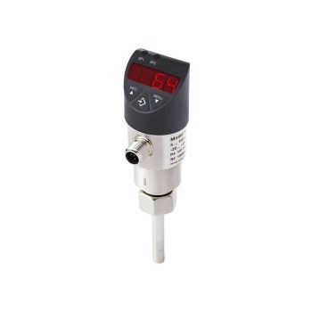
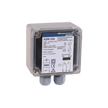
- Wear-free flow monitoring of liquid media using them calorimetric principle
- Flexibly configurable switching and analogue outputs for flow and temperature
- Easily parameterisable via 3-button operation or optionally via IO-Link 1.1
- Exact adaptation to the conditions on-site
 Datasheet Datasheet
|
|
User Manual
|
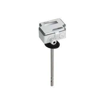
- Electrical output signal DC 0 … 10 V or 4 … 20 mA, can be selected directly at the instrument via jumpers
- Output signal for velocity and air temperature in one instrument
- With switching output
- Mounting flange for mounting on circular ventilation pipes or rectangular ventilation ducts
- Maintenance-free
|
Datasheet
|
|
User Manual
|
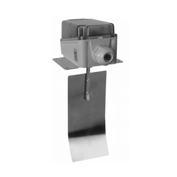
| Switch function/capacity | SPDT, capacity 250 Vac, 15(8) A |
| Setpoint device | screw |
| Sensing element | paddle |
| Flow setpoint range | 2.5 ... 9.2 m/s |
| Outputs | 1xSPDT |
| Mounting place | air duct |
| Immersion depth | 175 mm |
| IP class | IP65 |
| Medium type | air |
| Max. pressure | 0.25 bar |
| Media temp. | -40 ... 85 oC |
|
Datasheet
|
| Switch function/capacity | SPDT, capacity 250 Vac, 10(2) A |
| Sensing element | probe |
| Flow setpoint range | 0.1 ... 30 m/s |
| Outputs | 1xSPDT |
| Mounting place | air duct |
| Immersion depth | 130 mm |
| IP class | IP65 |
| Medium type | air |
| Max. pressure | 10 bar |
| Setpoint device | inside |
| Media temp. | -10 ... 80 oC |
| Additional description | LED's available for indication of power supply and switch status. |
|
Datasheet
|
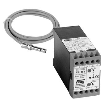
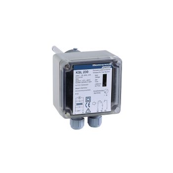
| Air flow monitor consisting of two parts: the sensor type SLF.. and the belonging evaluation unit type ASL... |
| For air flow monitoring in air-conditioning systems, ventilation and cooling systems and wherever flow processes in air or neutral gases have to be detected. |
|
Datasheet
|
| Switch function/capacity | SPDT, capacity 250Vac, 15(8) A |
| Setpoint device | screw |
| Sensing element | paddle |
| Flow setpoint range | 0.6 ... 165 m3/h pipe size dependent |
| Outputs | 1xSPDT |
| Mounting place | in pipe |
| Immersion depth | paddle dependent, 25..300 mm |
| IP class | IP65 |
| Media temp. | -40 ... 120 oC |
|
Datasheet
|
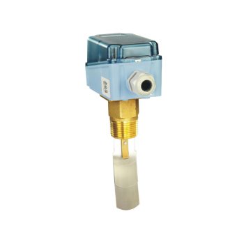
| Switch function/capacity | SPDT, capacity 250 Vac, 6 A |
| Setpoint device | inside |
| Sensing element | probe |
| Flow setpoint range | 0.05 ... 3 m/s |
| Outputs | 1xSPDT |
| Mounting place | in pipe |
| Immersion depth | 45 mm |
| IP class | IP65 |
| Medium type | liquid |
| Max. pressure | 20 bar |
| Media temp. | -10 ... 80 oC |
| Additional description |
LED's available for indication of power supply and switch status. |
|
Datasheet
|
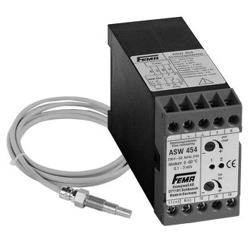
| Sensing element | probe |
| Flow setpoint range | with ASW unit 0.05/0.5 ... 3/20 m/s |
| Mounting place | in pipe or duct |
| IP class | IP65 |
| Medium type | liquid or air |
| Max. pressure | 20 bar |
| Media temp. | -15 ... 80 oC |
| Additional description | LED available for indication of power supply |
|
Datasheet
|
