


Temperature transmitters are a central link between temperature sensor and control system. They convert the signal of a Pt100, Pt1000, thermocouple or other temperature sensor into a standardized output signal, often 4–20 mA or a digital signal. However, if incorrect temperature values are displayed in a plant, the cause is not automatically the transmitter itself. Sensor, connection cable, reference junction, measuring range, scaling and PLC evaluation can be involved as well.
Especially in the process industry, furnace construction, HVAC, laboratories, mechanical engineering and maintenance, temperature errors often result from an incompletely checked measurement chain. A Pt100 can be correct but connected incorrectly in 2-wire technology. A thermocouple can work, but the cold junction may be incorrectly compensated. A transmitter can provide a correct 4–20 mA signal while the PLC still calculates using an old measuring range.
This article explains how temperature transmitters can be checked and calibrated effectively, why Pt100 simulation, thermocouple simulation and output signal should be considered together, and what role 2-/3-/4-wire connection, cold junction, sensor break detection, measuring range, 4–20 mA output and documentation play.
Table of contents
- Basics: what does a temperature transmitter do?
- Considering the complete measurement chain: sensor, cable, transmitter and PLC
- Checking Pt100 and RTD: correctly evaluating 2-, 3- and 4-wire connection
- Checking thermocouples: type K, J, N and the cold junction
- Checking 4–20 mA output and scaling
- Testing sensor break, short circuit and error behavior
- Distinguishing calibration, adjustment and functional testing
- Typical influencing factors: cable, environment, installation and interference
- Documentation and test report
- Practical example: temperature display 12 °C too high
- Which measuring instruments / products are suitable?
- Conclusion: always check temperature transmitters as a measurement chain
- FAQ: frequently asked questions about calibrating temperature transmitters
Basics: what does a temperature transmitter do?
A temperature transmitter processes the signal of a temperature sensor and provides it to the plant as a standardized signal. With a Pt100 or Pt1000, a resistance value is evaluated. With a thermocouple, a very small thermoelectric voltage in the millivolt range is detected. The transmitter converts this input information into a temperature value and then into an output signal.
In industrial plants, the output signal is often 4–20 mA. For example, 4 mA may correspond to 0 °C and 20 mA to 200 °C. Other ranges are also possible, such as -50…+150 °C, 0…600 °C or customer-specific measuring spans. In addition, HART, digital interfaces, switching outputs or diagnostic messages can be used.
The transmitter is therefore a translator between the sensor world and the control system world. If a temperature is displayed incorrectly, it must be checked whether the error lies on the sensor input side, in the transmitter, in the output signal or in the evaluation. Simply checking the display is not sufficient.
| Part of the measurement chain | Typical task | Possible error |
|---|---|---|
| Temperature sensor | Detects the temperature in the process | Drift, wrong sensor type, mechanical damage, poor installation |
| Connection cable | Transmits resistance or thermoelectric voltage signal | Lead resistance, wrong compensation cable, contact fault, interference |
| Temperature transmitter | Converts sensor signal into output signal | Wrong input type, wrong measuring range, defective reference junction, wrong linearization |
| 4–20 mA output | Transmits the temperature value to PLC or display | Incorrect scaling, load, loop supply, signal error |
| PLC / display / control system | Displays, processes or documents the measured value | Wrong measuring range, wrong unit, old parameterization, rounding or linearization error |
Considering the complete measurement chain: sensor, cable, transmitter and PLC
When calibrating a temperature transmitter, it is crucial to define which level is to be tested. If only the transmitter is checked, defined Pt100, RTD or thermocouple signals are simulated at the input and compared with the output signal. If the complete measuring point is checked, the real sensor, including installation, cable and process conditions, must also be considered.
Typical troubleshooting begins with the question of whether the displayed temperature is plausible at all. If it deviates from a reference, the transmitter should not immediately be replaced. First, it must be clarified whether the correct sensor type is parameterized, whether the cable is connected correctly, whether the measuring range is correct and whether the PLC converts the 4–20 mA signal correctly.
Especially in older plants, transmitters and control systems are often not documented cleanly. The transmitter may have been re-parameterized from 0…100 °C to 0…150 °C, while the PLC still works with the old range. Or a type K thermocouple may have been replaced by type J without adapting the parameterization. Such errors create apparently “wrong sensor values”, although the actual cause lies in the measurement chain.
A meaningful test is therefore built up in several stages: simulate the input signal, measure the output signal, compare the PLC display and, if necessary, check the real sensor separately with a reference. This makes it much faster to narrow down the source of the error.
Checking Pt100 and RTD: correctly evaluating 2-, 3- and 4-wire connection
Pt100 sensors are among the most commonly used temperature sensors in industry and building technology. Their resistance changes with temperature. A temperature transmitter measures this resistance and calculates the temperature from it. The connection is decisive here: 2-wire, 3-wire and 4-wire technology behave differently with regard to lead resistance.
With a 2-wire connection, the resistance of the connection cable is added directly to the sensor resistance. This can make the measured temperature appear too high, especially with long cables or small measuring ranges. With 3-wire technology, the cable influence is largely compensated if the wires have equal resistance. 4-wire technology is the most accurate, because the transmitter can detect the sensor resistance practically separately from the lead resistances.
During the test, a Pt100 simulator or multifunction calibrator is connected to the input of the transmitter. The calibrator provides defined resistance values or temperature points. It is then checked whether the transmitter provides the expected value at the output. It is important that the calibrator is used in the same connection type that is also set in the transmitter.
| Connection type | Characteristic | Typical error |
|---|---|---|
| 2-wire | Simple connection, cable influence is measured as well | Temperature is displayed too high due to lead resistance. |
| 3-wire | Good compensation with equal lead resistances | Unequal wires or incorrect wiring lead to measurement deviations. |
| 4-wire | Very accurate resistance measurement with low cable influence | Wrong terminal assignment or parameterization can eliminate the advantage. |
| Pt100 / Pt1000 confused | Different nominal resistances at 0 °C | Measured value is clearly wrong although sensor and cable are intact. |
Checking thermocouples: type K, J, N and the cold junction
Thermocouples work differently from Pt100 sensors. They generate a small voltage that depends on the temperature difference between the measuring junction and the reference junction. For this reason, with thermocouples not only the sensor type is important, but also the cold junction, the compensation cable and the correct polarity.
A type K, J, T or N thermocouple each has its own characteristic curve. If the wrong type is set in the transmitter, significant measurement errors occur. The use of incorrect compensation cables can also falsify the measurement. With thermocouples, it is not permissible simply to use any copper cable as an extension if the connection point is not correctly taken into account.
The cold junction is one of the most common sources of error. Since the thermocouple only generates a temperature difference, the temperature at the connection point must be known or compensated. Many transmitters have internal cold junction compensation. If this works incorrectly, is installed unfavorably or is influenced by ambient temperature gradients, the displayed temperature value can deviate.
For testing, a thermocouple calibrator is used that simulates defined thermocouple signals. It is important to know whether the calibrator works with internal cold junction compensation, whether the connection point is stable and whether the correct thermocouple type has been set. In addition, polarity should be checked, because reversed thermocouple wires can lead to strongly incorrect or opposite display behavior.
| Check point | Why important? | Typical error |
|---|---|---|
| Thermocouple type | Each type has a different characteristic curve | Type K set, but type J connected. |
| Polarity | Thermoelectric voltage has a direction | Reversed wires lead to incorrect or falling display. |
| Compensation cable | Cable material must match the thermocouple type | Wrong cable creates additional measuring junctions and measurement errors. |
| Cold junction | Thermocouple measures temperature difference, not absolute temperature alone | Faulty compensation shifts the entire measured value. |
| mV signal | Very small voltages are susceptible to interference | EMC, poor terminals or contact resistances influence the measurement. |
Checking 4–20 mA output and scaling
The output of a temperature transmitter is often designed as a 4–20 mA signal. This signal must clearly match the configured temperature range. For example, if the transmitter is parameterized to -50…+150 °C, the PLC must also use this range. If the PLC instead calculates with 0…200 °C, an electrically correct signal is displayed as an incorrect temperature.
During testing, the input signal should be simulated and the output signal measured at the same time. Example: the calibrator simulates 100 °C at the Pt100 input. The transmitter is set to 0…200 °C = 4…20 mA. The output must then provide 12 mA. If the PLC does not display 100 °C at 12 mA, the error is probably in the scaling of the PLC or display.
A loop calibrator such as the UPS4E loop calibrator is suitable for such tests. It can be used to measure and simulate 4–20 mA signals and test current loops. Especially during commissioning, device replacement, troubleshooting and maintenance, this helps to quickly narrow down errors between transmitter, display and PLC.
The loop supply is also important. Some transmitters are 2-wire devices and require an external supply in the current loop. Other devices have active outputs or separate supply. If the loop is supplied incorrectly or the load is too high, the output signal can be limited, unstable or implausible.
Testing sensor break, short circuit and error behavior
Modern temperature transmitters can detect sensor faults and output defined error behavior. With Pt100, a wire break or short circuit can be detected. With thermocouples, an open sensor can lead to an error state. Depending on parameterization, the output signal then moves upscale, downscale or to a defined error value.
For safety- or quality-relevant measuring points, this function should not only be listed in the data sheet, but also tested in practice. A sensor break can be simulated at the input, for example by opening the cable. It is then checked whether the transmitter and PLC show the desired reaction.
A common error is that the transmitter correctly outputs an error current signal, but the PLC does not interpret this state as a fault. A measured value outside the range or a frozen value then appears without maintenance personnel immediately recognizing that the measuring point is defective.
Sensor break detection, error current, alarm limits and fault messages should therefore be documented together. Especially in furnace processes, cooling circuits, sterilization, laboratory processes or safety-relevant temperature limits, this test can be crucial.
Distinguishing calibration, adjustment and functional testing
In everyday use, the terms calibration, adjustment and testing are often mixed up. During calibration, it is determined and documented how much the display or output signal deviates from the reference value. Adjustment changes the device in order to reduce the deviation. A functional test shows whether the measuring point basically works, but does not replace a complete calibration.
For a temperature transmitter, calibration can include several points. Typical points are, for example, 0 %, 50 % and 100 % of the measuring range. In critical applications, additional points may be useful, for example at the actual working point of the process. With thermocouples, cold junction compensation should be considered. With Pt100, the connection type should be documented.
A pure output test with 4–20 mA is useful, but it says nothing about whether the sensor input is working correctly. Conversely, pure Pt100 simulation does not show whether the PLC scales the output signal correctly. For this reason, the combined test of input and output is particularly important for temperature transmitters.
Before adjustment, it should always be checked whether the error is not caused by parameterization, connection cable, wrong sensor type or PLC scaling. Otherwise, a device that is actually correct is “adjusted” to compensate for a plant error, which later leads to new deviations.
Typical influencing factors: cable, environment, installation and interference
Temperature measurements are sensitive to installation and environmental conditions. A Pt100 in a thermowell only measures correctly if the thermal coupling to the process is sufficient. A thermocouple only measures reliably if measuring junction, compensation cable and reference junction are implemented cleanly. The transmitter can work correctly and the plant can still show wrong values if the sensor is installed unfavorably.
Long cables, poor terminals, moisture, EMC interference, incorrect shielding or parallel routing with power cables can influence the measurement. With thermocouples, the signal voltages are very small, so transitions and interference can have a particularly strong effect. With Pt100, lead resistances and connection type are central points.
The ambient temperature of the transmitter also plays a role. A head transmitter directly on a hot process connection or in a strongly heated control cabinet may experience different conditions than in the laboratory. Depending on the device, ambient temperature, self-heating and temperature gradients can influence accuracy and long-term stability.
Calibration should therefore match the application. For a pure device test, simulation at the input is sufficient. For a real measuring point evaluation, it must also be checked whether sensor, installation, heat transfer, cable and evaluation match the process.
Documentation and test report
Calibration is only useful in the long term if it is documented traceably. The test report should not only include the measured value, but also the measuring range, sensor type, connection type, test points, reference device, environment, output signal and evaluation of the deviation.
With temperature transmitters, it is particularly important to document the input and output sides separately. Was a Pt100 simulated? In which connection type? Which temperature range was set? Was the 4–20 mA output measured directly at the transmitter or at the PLC? Was the display in the control system also checked?
Parameterization is also part of the documentation. This includes sensor type, measuring range, unit, damping, error behavior, sensor break detection, output scaling and, if applicable, HART or digital settings. Without this information, later troubleshooting is significantly more difficult.
| Documentation point | Why important? | Example |
|---|---|---|
| Sensor type and connection type | Determines input signal and cable errors | Pt100, 3-wire or thermocouple type K |
| Measuring range | Determines output scaling | 0…200 °C = 4…20 mA |
| Test points | Shows deviation across the range | 0 °C, 100 °C, 200 °C |
| Output signal | Checks conversion into mA or digital signal | 12.000 mA at 100 °C |
| PLC / display value | Shows scaling errors in the evaluation | PLC correctly displays 100 °C at 12 mA |
Practical example: temperature display 12 °C too high
In a process plant, a temperature transmitter on a pipeline permanently displays about 12 °C more than a mobile reference measurement. Initially, it is assumed that the Pt100 has aged or that the transmitter is drifting. The sensor is to be replaced as a precaution.
During the test, the Pt100 input of the transmitter is first simulated with a calibrator. The points 0 °C, 50 °C and 100 °C are specified. The transmitter provides the expected 4–20 mA values. The PLC display also matches the mA scaling. The transmitter itself is therefore not the cause.
The real wiring is then checked. It turns out that a Pt100 is connected in 2-wire technology over a long cable. The additional lead resistance is interpreted by the transmitter as a higher temperature. This causes the positive deviation. After switching to suitable 3-wire technology and correct parameterization, the display is again much closer to the reference value.
The example shows why a complete measurement chain test is important. Without separate testing of input simulation, output signal, PLC scaling and real sensor connection, the transmitter would have been replaced unnecessarily.
Which measuring instruments / products are suitable?
For checking temperature transmitters, the category process calibrators / electrical calibrators is a useful starting point. There you will find devices for electrical signals, current loops, voltage, mV, resistance, RTD, thermocouples and other calibration tasks. Multifunction calibrators are particularly practical for extensive commissioning and maintenance work.
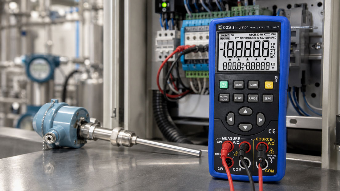
The category simulators is particularly relevant when defined sensor signals need to be generated. For Pt100, RTD, thermocouple, mV and V, for example, the ICS 02S simulator for Pt100, RTD, TC and mV/V can be used. This allows sensor values to be simulated and transmitters or controllers to be checked in a targeted way.
For thermocouple applications, the C.A 1621 calibrator for thermocouple sensors is a suitable solution. It is suitable for measuring and simulating common thermocouple types such as J, K, T, E, R, S, B and N. This allows thermocouple inputs of transmitters, controllers or displays to be checked independently of the real sensor.
If the temperature transmitter outputs a 4–20 mA signal, the UPS4E loop calibrator is also useful. It helps to measure or simulate mA signals, test current loops and identify scaling errors between transmitter, display and PLC.
| Product / area | Typical use | Particularly relevant for |
|---|---|---|
| Process calibrators / electrical calibrators | Testing electrical process signals and measurement chains | Temperature transmitters, current loops, mV, V, resistance, RTD and TC |
| Simulators | Simulation of defined sensor and process signals | Pt100, RTD, thermocouples, mV, V and controller testing |
| ICS 02S simulator for Pt100, RTD, TC and mV/V | Measurement and simulation of temperature and voltage signals | Pt100 simulation, thermocouple simulation, transmitter and controller testing |
| C.A 1621 calibrator for thermocouple sensors | Thermocouple measurement and simulation | Types J, K, T, E, R, S, B, N, mV signals and thermocouple inputs |
| UPS4E loop calibrator | Testing and simulation of 4–20 mA signals | PLC scaling, transmitter output, commissioning, device replacement and troubleshooting |
Conclusion: always check temperature transmitters as a measurement chain
Calibration of a temperature transmitter should not be understood only as a device test. In practice, temperature errors are often caused by sensor connection, lead resistance, wrong sensor type, cold junction, measuring range, 4–20 mA scaling or PLC parameterization. The complete measurement chain must therefore be considered.
With Pt100 measurements, connection type and lead resistance are particularly important. With thermocouples, thermocouple type, compensation cable, polarity and cold junction are the focus. With 4–20 mA outputs, correct scaling determines whether an electrically correct signal is also displayed as the correct temperature value.
The most important recommendation is: check input and output together. Anyone who simulates Pt100 or thermocouple signals, measures the 4–20 mA signal at the same time and compares the PLC display quickly recognizes whether the error lies in the sensor, transmitter, wiring or evaluation.
FAQ: frequently asked questions about calibrating temperature transmitters
What is a temperature transmitter?
A temperature transmitter converts the signal of a temperature sensor, for example Pt100 or thermocouple, into a standardized output signal. This is often a 4–20 mA signal for PLC, display or control system.
Why should you not only test the transmitter?
Because temperature errors can also be caused by sensor, connection cable, wrong sensor type, cold junction, lead resistance or PLC scaling. A pure device test does not always find these errors.
How do you test a Pt100 input?
A Pt100 input is tested with an RTD or Pt100 simulator. The calibrator provides defined temperature points or resistance values. It is then checked whether the transmitter generates the correct output signal.
What is the difference between 2-, 3- and 4-wire technology?
With 2-wire technology, lead resistance is measured as well. 3-wire technology largely compensates for this influence. 4-wire technology offers the most accurate resistance measurement because the lead resistance is practically considered separately from the sensor value.
Why does a Pt100 sometimes show temperatures that are too high?
A common cause is additional lead resistance, especially with 2-wire connection and long cables. The transmitter interprets the additional resistance as a higher temperature.
How do you test a thermocouple input?
A thermocouple input is tested with a thermocouple calibrator. It simulates defined thermocouple signals for the configured type, for example K, J or N. Reference junction and polarity must be considered.
What is the cold junction?
The cold junction is the connection point where the thermocouple is connected to the measuring device. Since a thermocouple measures a temperature difference, this reference junction temperature must be known or compensated.
What happens with the wrong thermocouple type?
If a different thermocouple type is set on the transmitter than the one actually connected, the characteristic curve does not match. This can lead to significant measurement errors.
Why is the compensation cable important with thermocouples?
The compensation cable must match the thermocouple type. If an unsuitable cable is used, additional thermoelectric voltages can occur and falsify the measured value.
How do you test the 4–20 mA output?
The input of the transmitter is simulated with a defined sensor value. At the same time, the mA output signal is measured. It is then checked whether this signal matches the configured temperature span.
How do you recognize incorrect PLC scaling?
If the mA signal is correct but the PLC displays an incorrect temperature value, the scaling in the PLC or display is probably wrong. In that case, measuring range or unit does not match the transmitter.
What does sensor break detection mean?
Sensor break detection means that the transmitter detects an interrupted sensor cable and outputs defined error behavior. This can be an error current, an alarm message or a defined output state.
Should sensor break be tested in practice?
Yes, especially at safety- or quality-relevant measuring points. This checks whether transmitter and PLC report the expected fault in the event of cable break or sensor failure.
What is the difference between calibration and adjustment?
Calibration means determining and documenting the deviation. Adjustment means changing the device to reduce the deviation. A functional test only shows whether the measuring point basically works.
Which test points are useful?
Typical test points are 0 %, 50 % and 100 % of the measuring range. In critical applications, testing should additionally be performed at the real working point of the process.
Which information belongs in the test report?
Important information includes sensor type, connection type, measuring range, test points, reference device, input simulation, output signal, PLC display, deviation, environment, date and tester. Parameterization should also be documented.
Which devices are needed for testing?
Depending on the measuring point, a Pt100/RTD simulator, thermocouple calibrator, multifunction calibrator or loop calibrator is required. For 4–20 mA outputs, a loop calibrator is particularly helpful.