


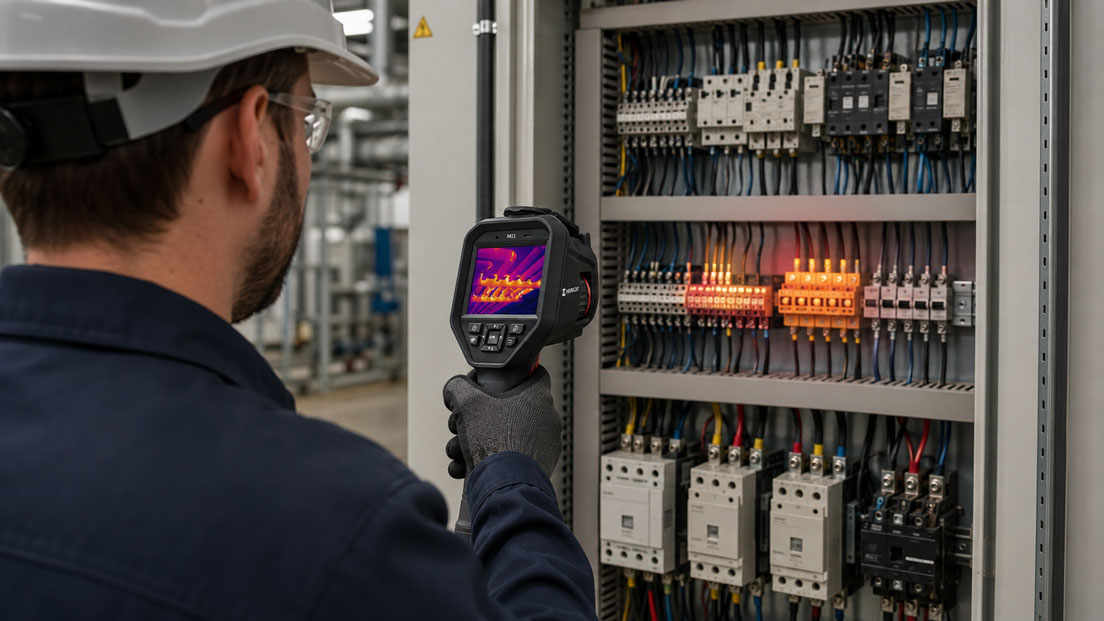
Loose terminals, worn contacts and overloaded equipment are often indicated by an increased temperature. A thermal imaging camera can detect such thermal anomalies before they lead to shutdowns, damaged components or production downtime.
Thermography is particularly useful because the control cabinet can be inspected during normal operation. This makes faults visible that would not occur when the system is de-energised. A loose connection, for example, only heats up when sufficient current flows through the increased contact resistance.
However, a bright or red area in the thermal image does not automatically indicate a fault. Fuses, contactors, frequency converters and power supplies regularly generate heat during operation. The decisive factors are temperature differences compared with similar components, the current load, the ambient temperature and the development over time.
This article explains how control cabinets are inspected using thermography, how typical fault patterns can be identified and why emissivity, reflections and safety distance are important for a reliable assessment.
Table of contents
- What a thermal imaging camera detects in a control cabinet
- Why the system should be inspected under load
- Safety when inspecting an open control cabinet
- Typical thermal fault patterns
- Detecting loose and overheated terminals
- Assessing fuses and fuse holders
- Inspecting contactors and circuit breakers
- Applying phase comparison correctly
- Considering emissivity and reflections
- Resolution, focus and measuring distance
- Professionally assessing hotspots
- Documenting and comparing measurements
- Systematic inspection procedure
- Practical example: Overheated incoming terminal
- Typical thermography errors
- Which measuring instruments / products are suitable?
- Conclusion
- Frequently asked questions about control-cabinet thermography
What a thermal imaging camera detects in a control cabinet
A thermal imaging camera detects infrared radiation emitted and reflected by a surface. From this, it calculates an apparent surface temperature and displays temperature differences as a thermal image.
In a control cabinet, this can reveal anomalies such as:
- increased contact resistance at terminals and contacts
- overloaded cables and equipment
- unevenly loaded phases
- defective fuse holders or circuit breakers
- overheated contactor and relay contacts
- insufficient ventilation or cooling
- local heat build-up around frequency converters and power supplies
The camera measures only the visible surface. An internal contact fault can therefore only be detected indirectly through heating of the housing, connection or conductor.
Metal doors and closed covers are not transparent to conventional thermal imaging cameras. Reliable inspection therefore requires safe visual access to the component or a suitable infrared inspection window.
Why the system should be inspected under load
Many electrical faults only generate their characteristic heating under load. If a control cabinet is inspected immediately after switch-on or while the system is operating at low capacity, an existing fault may remain undetected.
The measurement should therefore be carried out under a representative operating condition wherever possible. The following values should be documented in particular:
- current load current
- utilisation of the machine or system
- ambient temperature
- operating time before the measurement
- switching state of relevant loads
A comparison with an earlier image is only meaningful if the operating conditions are similar. A terminal at 80% system load cannot readily be compared with an image recorded at 20% load.
After major load changes, sufficient time should be allowed for a largely stable thermal condition to develop.
Safety when inspecting an open control cabinet
For a thermographic inspection, covers often have to be removed or control-cabinet doors opened. This can make live parts accessible and increase the risk of electric shock or arc flash.
Work and measurements on open electrical installations may only be performed by appropriately qualified electricians in accordance with the applicable company safety regulations.
Before the measurement, the following points should be checked, among others:
- rated voltage and short-circuit capacity of the installation
- required safety distance
- necessary personal protective equipment
- safe position of the inspector
- condition of covers and interlocks
- possible hazards caused by moving system components
The thermal imaging camera enables contactless measurement. However, it does not eliminate the hazards associated with an open control cabinet.
Suitable infrared windows can simplify inspections on critical installations that are checked regularly. Their transmission must be taken into account during temperature measurement.
Typical thermal fault patterns
The shape and distribution of the heating often provide an initial indication of the cause.
| Thermal appearance | Possible cause | Further inspection |
|---|---|---|
| Localised hot connection | Loose terminal, corrosion or increased contact resistance | De-energise the circuit and inspect the connection professionally |
| Entire conductor evenly warm | High load current or insufficient conductor cross-section | Measure the current and check the design |
| One phase significantly warmer | Unbalanced load or contact problem | Compare phase currents and connection points |
| Fuse hot at one end | Contact problem in the fuse holder | Check the holder, clamping and contact surfaces |
| Several devices warm in the upper section | Heat accumulation or insufficient ventilation | Check the control-cabinet climate control |
| Contactor locally warm at one main contact | Contact wear or increased contact resistance | Check the condition of the contact and the voltage drop |
A thermal anomaly initially provides an indication of a possible fault. The cause should then be confirmed through electrical measurements and an inspection while the system is de-energised.
Detecting loose and overheated terminals
A loose or damaged terminal frequently has increased contact resistance. When current flows through this point, local power loss is generated.
A typical indication is a sharply defined hotspot directly at the terminal point. The connected conductor may also heat up from this point, with the temperature often decreasing as the distance from the terminal increases.
Overloading, by contrast, generally results in more uniform heating over a larger length of conductor or component.
Possible causes of an abnormal terminal include:
- insufficient tightening torque
- conductor not fully inserted
- unsuitable or damaged ferrule
- corrosion or contamination
- mechanical loosening caused by vibration
- thermal ageing of the contact point
A suspicious terminal must not be retightened while the system is operating. The circuit must be safely de-energised and the connection checked in accordance with the manufacturer’s and company’s requirements.
Assessing fuses and fuse holders
Fuses heat up under load. A certain increase in temperature is therefore not automatically unusual.
Indications of a possible fault include:
- a significant temperature difference between three equally loaded fuses
- strong heating at only one contact end
- a hotspot on the fuse holder rather than on the fuse element
- discolouration or damaged plastic components
- increasing temperature despite unchanged load
A warm fuse may also be caused by a higher current in the corresponding phase. The actual phase currents should therefore be measured before an assessment is made.
If a local hotspot is detected on the holder, the contact surfaces, terminal connections and mechanical seating must be checked. Simply replacing the fuse does not eliminate a defective holder.
Inspecting contactors and circuit breakers
Contactors can heat up due to the coil, main contacts and load current. Uniform heating of the coil area may be inherent to the design.
A significantly hotter individual main connection or a temperature difference between comparable contact paths is more unusual.
Possible causes include:
- worn or burnt main contacts
- loose connection terminal
- uneven phase loading
- excessive switching frequency
- unsuitable sizing
Circuit breakers and motor-protection switches also generate heat under load. An elevated temperature may be caused by normal current flow, a contact problem or excessive loading.
The load current, voltage drop, manufacturer’s specifications and comparable components should be included in the further assessment.
Applying phase comparison correctly
In three-phase installations, comparing L1, L2 and L3 is one of the most effective assessment methods. Identical fuses, terminals and switching contacts should show similar thermal behaviour when subjected to similar loads.
One significantly warmer phase may indicate a contact problem or uneven load distribution.
However, a phase comparison is only reliable if:
- the components are identical
- the phase currents are known
- the surfaces are comparable
- the measuring angle and distance are similar
- there are no different airflows
Different temperatures can be normal with strongly unbalanced loads. The thermal image should therefore be combined with a simultaneous current measurement wherever possible.
Considering emissivity and reflections
Emissivity describes how effectively a surface emits infrared radiation. Dark, matt and non-metallic surfaces frequently have a higher emissivity than bare metals.
Shiny copper busbars, screws and metallic terminals can strongly reflect radiation from the surroundings. The camera may then display a reflection of the operator, a lamp or a nearby hot component instead of the actual surface temperature.
Indications of a reflection include:
- the hotspot moves when the camera angle is changed
- the displayed temperature changes significantly with the camera position
- a shiny surface appears warmer than adjacent insulating material
- the shape of the warm area corresponds to a reflected heat source
For quantitative measurements, the emissivity and reflected temperature must be set appropriately. Suitable reference surfaces can be used at prepared measuring points. Such markings may only be applied when the installation is safely de-energised.
For highly reflective surfaces, a relative comparison with the same type of surface is often more reliable than a single absolute temperature value.
Resolution, focus and measuring distance
For a small terminal to be assessed reliably, it must be captured by a sufficient number of infrared pixels. If the component occupies only one or two pixels in the thermal image, its temperature is mixed with the cooler surroundings.
This results in the actual hotspot temperature being displayed too low.
The following factors are therefore important for detailed images:
- sufficient thermal resolution
- suitable field of view
- correctly adjusted focus
- the shortest possible but safe measuring distance
- steady camera handling
A wide-angle lens makes it easier to capture a complete control cabinet from a short distance. For small terminals viewed from a greater safety distance, however, a narrower field of view or higher spatial resolution may be advantageous.
Digital zoom merely enlarges the existing pixels. It does not replace adequate detector resolution or suitable optics.
Professionally assessing hotspots
There is no universal temperature value above which every electrical component is automatically defective. The permissible temperature depends, among other things, on the component type, current load, insulation class, ambient conditions and manufacturer’s specifications.
Several criteria should therefore be combined for the assessment:
- temperature difference compared with similar components
- temperature difference compared with the surroundings
- actual load current
- position and shape of the hotspot
- earlier measurements of the same point
- visible discolouration or material damage
A small local temperature increase at a connection point may be more critical than an overall warmer power supply designed for elevated operating temperatures.
The thermal assessment should therefore not be based solely on the camera’s automatic hotspot marker.
Documenting and comparing measurements
A thermographic image only provides long-term value if the measuring point and operating condition are documented in a traceable manner.
Meaningful documentation should include:
- designation of the installation and control cabinet
- date and time
- thermal image and visible-light comparison image
- component and exact position
- load current or system load
- ambient conditions
- configured emissivity
- assessed temperature difference
- recommended action
For trend comparisons, the same camera position, image section and temperature range should be used wherever possible.
This makes it possible to determine whether a known anomaly is becoming more severe or has disappeared following a repair.
Systematic inspection procedure
- Prepare the installation: Check the circuit diagram, operating condition and expected loads.
- Define safety measures: Assess the hazard and use suitable protective equipment.
- Configure the camera: Check the temperature range, emissivity, reflected temperature and distance.
- Create an overview image: Inspect the entire control cabinet for abnormal areas.
- Capture detailed images: Record suspicious terminals, fuses and contacts with correct focus.
- Compare phases: Compare identical components and the associated load currents.
- Document measured values: Save the thermogram, visible-light image and operating data.
- Confirm the cause: Safely de-energise the installation and carry out electrical or mechanical inspection.
- Perform a follow-up inspection: Thermographically inspect the repaired point again under a comparable load.
Practical example: Overheated incoming terminal
During the regular thermographic inspection of a low-voltage distribution board, an incoming terminal on L2 is clearly noticeable. Under comparable loading, L1 and L3 are at approximately 42 °C, while the L2 terminal reaches around 68 °C.
The connected conductor is strongly heated only directly at the terminal. Its temperature drops significantly just a few centimetres away. This pattern is more indicative of increased contact resistance than of general conductor overloading.
A current measurement shows that all three phases are subjected to similar loads. Different phase loading can therefore largely be excluded as the cause.
After the system has been safely de-energised, it is found that the conductor is not fully seated in the terminal. Slight discolouration is also visible at the contact point.
The connection is renewed in accordance with the manufacturer’s instructions. During the subsequent inspection under a comparable load, the temperatures of all three phases are once again within a similar range.
The example demonstrates the benefit of repeated thermographic inspections: The connection could be repaired before the increasing temperature caused a shutdown or more extensive damage.
Typical thermography errors
| Error | Possible consequence | Better approach |
|---|---|---|
| Measurement performed at low system load | Contact fault remains thermally inconspicuous | Inspect under a representative load |
| Shiny metal surface assessed directly | Reflection is interpreted as a hotspot | Change the angle and consider the emissivity |
| Component too small in the image | Peak temperature is displayed too low | Adjust the distance and optics |
| Only the automatic hotspot display used | An irrelevant warm area is overestimated | Assess the component, load and temperature distribution professionally |
| Phases assessed without comparing the currents | Normal load imbalance is interpreted as a fault | Measure the phase currents simultaneously |
| Measuring conditions not documented | Later trend comparisons are unreliable | Record the load, ambient conditions and camera settings |
| Thermogram regarded as the final diagnosis | The actual cause of the fault remains unclear | Follow up with electrical and mechanical inspection |
Which measuring instruments / products are suitable?
The Advanced thermal imaging cameras category contains handheld cameras for industrial maintenance, electrical inspections and professional troubleshooting.
Devices from the Premium thermal imaging cameras category are available for particularly demanding requirements concerning resolution, optics and documentation.
HIKMICRO M11 for targeted detailed inspections
The HIKMICRO M11 features manual focus and is suitable for targeted images of terminals, fuses and other smaller components.
Its comparatively narrow field of view is useful when details need to be captured from a greater safety distance.
HIKMICRO M20W for control-cabinet overview images
The HIKMICRO M20W offers a wide field of view and is therefore particularly suitable for overview images in confined technical rooms and in front of larger control-cabinet panels.
After an abnormal area has been located, additional detailed images should be captured from a suitable distance.
HIKMICRO SP40 for professional inspections
The HIKMICRO SP40 is designed for detailed industrial thermography and extensive inspection tasks.
The higher thermal resolution and flexible lens alignment support the inspection of small components and repeated documentation of larger installations.
Selecting the appropriate thermal imaging camera
The size of the components to be inspected, the required safety distance, the available space in front of the control cabinet and the requirements for reports and trend analyses are particularly important selection criteria.
ICS Schneider Messtechnik assists with selecting a thermal imaging camera according to thermal resolution, field of view, focus, temperature range and documentation requirements.
Conclusion: Hotspots must be assessed under actual operating conditions
A thermal imaging camera enables fast, contactless inspection of terminals, fuses, contactors and circuit breakers. Local heating may indicate increased contact resistance, overloading or worn contacts.
A meaningful measurement requires a representative system load and safe visual access to the components. A camera cannot reliably measure the internal temperature through closed metal doors or conventional covers.
Comparing identical phases and repeatedly recording the same measuring points are particularly effective methods. The load current, ambient temperature and camera settings must be documented.
Shiny metal surfaces can reflect thermal radiation from the surroundings. Emissivity, measuring angle and reflected temperature must therefore be considered during the assessment.
A thermogram shows the thermal effect of a possible fault, but not automatically its cause. Abnormal points must subsequently be inspected professionally while the installation is de-energised and checked again under load after the repair.
Frequently asked questions about control-cabinet thermography
Can a thermal imaging camera measure through a closed control-cabinet door?
No. Metal doors and conventional covers are not transparent to the infrared radiation used. Safe visual access or a suitable infrared window is required.
Must the control cabinet be under load during the measurement?
Yes, preferably under a representative load. Many contact and overload faults only generate detectable heating when sufficient current is flowing.
Is every red area in a thermal image a fault?
No. The colour palette only represents relative temperatures. The measured value, load, comparable components and temperature distribution are decisive.
How can a loose terminal be identified?
A localised temperature increase directly at the terminal point is typical. However, a final diagnosis requires an inspection while the installation is safely de-energised.
Why are shiny screws difficult to measure?
Bare metal has a low emissivity and frequently reflects thermal radiation from the surroundings. This can significantly distort the displayed temperature.
Why should the current also be measured?
This makes it possible to distinguish whether a warmer phase is caused by a higher load or an electrical fault.
Which resolution does a thermal imaging camera need for control cabinets?
This depends on the component size and measuring distance. Small terminals viewed from a greater distance require higher thermal or spatial resolution than a general control-cabinet overview.
Can thermography replace a torque inspection?
No. It can detect a thermally abnormal connection, but does not replace a professional mechanical and electrical inspection.
How often should a control cabinet be inspected using thermography?
The interval depends on the criticality, load, operating conditions and previous findings. Critical installations and known anomalies should be checked more frequently.
What should be included in a thermography report?
The thermal image, visible-light comparison image, measuring point, load condition, ambient temperature, camera settings, temperature difference and recommended action should be documented in a traceable manner.
Which camera is suitable for confined control cabinets?
A wide field of view simplifies overview images from a short distance. For small connection points, the resolution, focus and spatial resolution must also be sufficient.
Which information does ICS Schneider require for selection?
The typical component size, measuring distance, temperature range, required resolution, available space, reporting requirements and planned frequency of use are needed.