


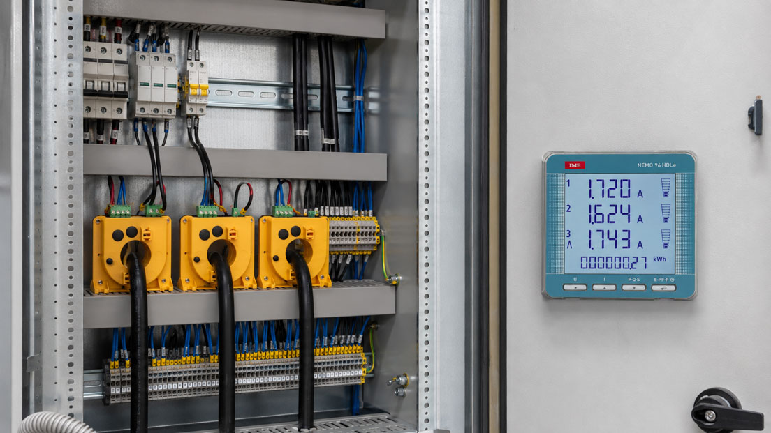
In many existing control cabinets, local measuring devices for recording energy consumption, power, current, voltage, or load profiles are missing. The system may be running, but operators and maintenance teams often cannot see which consumers require how much energy, whether individual outgoing feeders are overloaded, or whether load peaks occur during operation. Especially in retrofit projects, energy monitoring, load management, or machine optimization, an energy meter is therefore often retrofitted in the control cabinet.
A particularly practical solution is 96×96 panel meters. They are installed from the front into the control panel, are easy to read, and, depending on the version, can display current, voltage, power, energy, power factor, frequency, and other electrical network parameters. In combination with suitable current transformers, voltage taps, and communication interfaces, existing systems can often be monitored without a complete conversion.
For the retrofit to work reliably, the panel meter, current transformers, measuring range, wiring, phase assignment, and interface must all match. Many errors are not caused by the measuring device itself, but by incorrectly selected current transformers, swapped phases, incorrect transformer ratios, unsuitable burdens, or incorrect parameterization. This article explains what to consider when retrofitting an energy meter in a control cabinet.
Table of contents
- Why retrofit energy meters in control cabinets?
- 96×96 panel meter, DIN rail energy meter, or digital display?
- Which measured variables should be recorded?
- Selecting the right current transformers
- Understanding transformer ratio, 1 A / 5 A, and measuring range
- Considering accuracy class, burden, and cable length
- Split-core current transformers for retrofit applications
- Wiring: voltage path, current path, and phase relationship
- Connecting three-phase measurement correctly
- Interfaces: Modbus, pulse, relay, and digital data processing
- Scaling and parameterization in the panel meter
- Current transformers with transmitters and 4–20 mA signals
- Typical wiring and parameterization errors
- Practical example: Retrofitting a 96×96 energy meter in a machine distribution cabinet
- Which measuring instruments / products are suitable?
- Conclusion: Plan the retrofit properly instead of simply installing a device
- FAQ: Frequently asked questions about retrofitting energy meters in control cabinets
Why retrofit energy meters in control cabinets?
A retrofitted energy meter creates transparency in existing systems. While energy measurement is often already planned in new control cabinets, it is frequently missing completely in older distribution boards, machine controls, or sub-distributions. The operator may see the total consumption on the main meter, but cannot identify which machine, outgoing feeder, or consumer group is actually responsible for high energy costs.
Local energy and power measurement in the control cabinet helps identify consumption hotspots, build load profiles, make standby consumption visible, and assess overloads at an early stage. Especially in industrial plants, building services, production lines, test benches, compressors, pumps, refrigeration systems, and machine controls, such a retrofit can quickly provide significantly more transparency.
The advantage of a 96×96 panel meter lies in the combination of local display and technical integration. The current, voltage, power, or energy consumption can be read directly at the control cabinet door. At the same time, measured values can be passed on to an energy management system, PLC, or building management system via interfaces such as Modbus, pulse output, or relay contact.
However, when retrofitting, the question should not only be which measuring device fits into the door. The decisive factor is what information is to be obtained. Is it a simple kWh display, load monitoring, network parameters, energy auditing, consumption allocation, or digital data processing? Only from this question can the correct design, current transformer, accuracy, interface, and parameterization be derived.
| Retrofit objective | Typical measured variables | Important planning aspect |
|---|---|---|
| Make energy consumption visible | kWh, active power, current | Suitable transformer ratio and clear assignment to the consumer. |
| Detect load peaks | Power, current, maximum values | Consider measuring interval, memory function, or digital interface. |
| Monitor a machine feeder | Current, voltage, power, power factor | Correctly implement three-phase wiring and phase relationship. |
| Set up energy monitoring | kWh, load profile, network parameters | Plan a communication interface such as Modbus or pulse output. |
| Retrofit without long downtime | Current and energy | Check split-core current transformers and sufficient space in the control cabinet. |
96×96 panel meter, DIN rail energy meter, or digital display?
Various designs are available for retrofitting in control cabinets. A 96×96 panel meter is installed in a corresponding cutout in the control panel or control cabinet door. It provides a clearly visible front display and is particularly useful when operators, maintenance technicians, or energy managers need to read measured values directly at the control cabinet.
A DIN rail energy meter, on the other hand, is mounted inside the control cabinet on the DIN rail. This solution is compact and well suited when the measured values are mainly processed digitally or only read occasionally. In existing control cabinets, a DIN rail meter may be easier to retrofit if there is no door cutout or if the control cabinet door should not be modified.
Digital panel meters and digital displays are particularly versatile when individual measured variables need to be displayed. Depending on the version, they can display current, voltage, frequency, power, or other process signals. However, not every digital display device is automatically an energy meter. For energy consumption, active power, power factor, and three-phase network parameters, a suitable energy or network monitoring device is required.
The decision therefore depends on whether a simple display, an energy meter, a power analyzer, or a communication-capable measuring device is required. For a simple local display, a panel meter is often sufficient. For energy management, consumption analysis, or load profile analysis, however, attention should be paid to interfaces, memory function, the scope of measured variables, and data transmission.
| Design | Typical use | Advantage | To consider |
|---|---|---|---|
| 96×96 panel meter | Control cabinet door, operator panel, machine distribution cabinet | Very easy to read and professionally integrable. | Door or control panel cutout required. |
| DIN rail energy meter | Sub-distribution, retrofit inside the control cabinet | Compact and easy to mount on a DIN rail. | Readability depends on installation location. |
| Digital display | Display of individual measured variables such as current or voltage | Flexible for different input signals. | Not automatically suitable for complete energy metering. |
| Power analyzer | Load, network, and quality monitoring | Many measured variables and diagnostic options. | More complex parameterization and wiring. |
Which measured variables should be recorded?
Before selecting an energy meter, it should be clearly defined which measured variables are required. For simple consumption recording, active energy in kWh is often sufficient. However, if the current system load is to be assessed, current, voltage, active power, apparent power, and power factor are also important. For more in-depth network or load analysis, frequency, reactive power, phase angle, imbalance, or harmonics may become relevant.
In practice, people often initially search only for an “energy meter”. However, this can mean very different things: a simple kWh meter, a three-phase panel meter, a digital power display, a power analyzer, or an energy monitoring module. The more precisely the required function is described, the more reliably the right device can be selected.
For machines and production systems, assignment is especially important. Is the entire control cabinet being measured, an individual machine feeder, a consumer group, or a single motor? Depending on the measuring point, current range, transformer size, network type, and wiring can differ significantly.
The further processing of the measured values should also be clarified early. A local display is sufficient if the value only needs to be checked on site. For energy reports, load management, or central evaluation, interfaces such as Modbus, pulse outputs, or digital communication modules are required.
| Measured variable | Meaning | Typical application |
|---|---|---|
| Active energy kWh | Electrical energy actually consumed | Consumption recording, cost centers, submetering. |
| Active power kW | Current power consumption | Load monitoring and detection of peak loads. |
| Current A | Load on individual phases or feeders | Overload monitoring, dimensioning, machine analysis. |
| Voltage V | Supply voltage of the network | Network monitoring and plausibility check. |
| Power factor cos φ / PF | Ratio of active power to apparent power | Assessment of reactive power and consumer characteristics. |
| Frequency Hz | Network frequency | Monitoring of networks, generators, or island systems. |
Selecting the right current transformers
In many energy meters, the current is not routed directly through the measuring device, but is recorded via current transformers. This is common especially at higher currents. The current transformer reduces the primary current to a standardized secondary current, for example 5 A or 1 A. The panel meter then processes this secondary current and converts it back to the actual primary current using the stored transformer ratio.
Selecting the current transformer is one of the most important steps in the retrofit. The primary current range must match the actual load current. A transformer selected too large can cause poor resolution or higher relative measurement deviation at low currents. A transformer selected too small can be overloaded or exceed the measuring range.
The current transformer must also fit mechanically inside the control cabinet. The conductor diameter, busbar dimensions, available space, mounting type, and accessibility are decisive. In existing systems, it can be difficult to retrofit closed window-type current transformers if conductors cannot be disconnected or busbars cannot be loosened. In such cases, split-core current transformers are often the much more practical solution.
The current transformer must also match the accuracy requirement. Pure trend or load monitoring requires different specifications than near-billing energy recording, energy auditing, or accurate consumption allocation. Accuracy class, burden, cable length, and connected measuring devices should be considered together.
Understanding transformer ratio, 1 A / 5 A, and measuring range
The transformer ratio indicates which primary current corresponds to which secondary current. A 250/5 A current transformer supplies a secondary current of 5 A at 250 A primary current. The panel meter must know this ratio. If a different ratio is accidentally set in the measuring device, it will display incorrect currents, powers, and energy consumption values.
In practice, 5 A secondary circuits are very common. 1 A current transformers can offer advantages over longer cable runs because, with the same cable resistance, lower losses occur in the secondary circuit. However, the decisive factor is always which inputs the measuring device supports and which transformer configuration fits the system.
A common retrofit error is incorrect parameterization of the primary current. For example, if a 500/5 A transformer is used but the measuring device is set to 250/5 A, current, power, and energy will be calculated incorrectly. The error directly affects all derived measured values and cannot be recognized by the measuring device itself if the entered value appears plausible.
The selected primary current range should also match the real load. If a consumer normally draws only 20 A during operation, a 1000/5 A transformer is usually unfavorable because the measurement takes place in the lower range. For meaningful values, the usual operating current should be well within the usable range of the transformer without ignoring load peaks or starting currents.
| Parameter | Meaning | Effect of incorrect selection |
|---|---|---|
| Primary current | Maximum current on the system side | Too large: poor resolution; too small: overload or saturation. |
| Secondary current | Output current of the transformer, usually 1 A or 5 A | Measuring device and transformer do not match. |
| Transformer ratio | Conversion between primary and secondary current | Current, power, and energy are displayed incorrectly. |
| Accuracy class | Permissible measurement deviation within the defined range | Measurement is too inaccurate for the intended purpose. |
| Burden | Permissible load in the secondary circuit | Additional errors due to excessive cable or device input load. |
Considering accuracy class, burden, and cable length
The accuracy of an energy measurement does not depend only on the panel meter. Current transformers, cables, terminals, and parameterization also influence the result. Therefore, the measuring chain should be considered as a whole. A high-quality measuring device cannot deliver accurate energy recording if the current transformers are unsuitable or the secondary circuit has been incorrectly designed.
The accuracy class of the current transformer describes its measurement deviation under defined conditions. For simple operating displays, a less demanding class is often sufficient. For energy allocation, monitoring, or near-billing applications, more accurate transformers should be selected. In addition, the current range in which the system is actually operated must be considered.
The burden is also important. It describes the permissible load of the current transformer secondary circuit. Cable resistance, terminals, measuring device, and, if applicable, additional connected devices together form this load. If the permissible burden is exceeded, the current transformer can no longer operate within its specified accuracy.
With long cable runs between the current transformer and the panel meter, cable resistance increases. This can cause additional errors. In such cases, a 1 A secondary current may be more favorable than 5 A, provided the measuring device supports it. Alternatively, the measuring device can be placed closer to the transformer or the secondary cable can be dimensioned accordingly.
Split-core current transformers for retrofit applications
In existing control cabinets, mechanical retrofitting is often more difficult than electrical selection. If conductors or busbars should not be interrupted, closed window-type current transformers can only be installed with greater effort. Split-core current transformers can be placed around the existing conductor without completely opening the circuit.
This is a major advantage especially for retrofit projects, short downtime windows, or hard-to-access systems. The retrofit can be carried out faster, and the system may need to be disassembled less extensively. Nevertheless, with split-core current transformers, attention must also be paid to current range, accuracy, opening size, and secure mechanical locking.
Split-core current transformers are not automatically the best solution for every application. For high accuracy requirements, limited installation space, or unfavorable conductor routing, it must be checked whether the measurement quality is sufficient. The transformer should close completely, sit correctly around the conductor, and not be influenced by neighboring conductors or magnetic fields.
For simple load monitoring and retrofit applications, split-core current transformers are often very practical. For precise energy recording or defined measuring chains, a conventional window-type current transformer or an accuracy current transformer may be the better choice if installation is possible.
Wiring: voltage path, current path, and phase relationship
An energy meter calculates power and energy from voltage and current. Therefore, voltage path and current path must match each other correctly. If the current of phase L1 is measured but assigned to the voltage of L2, incorrect power values will result. The device may display currents and voltages, but active power, power factor, and energy meter readings will not be plausible.
The direction of the current transformer is particularly critical. Many current transformers have a defined primary direction, often marked by P1/P2 or arrows. If the transformer is mounted the wrong way round or S1/S2 are swapped, active power may be displayed as negative or the energy meter may count in the wrong direction. With a pure current display, this error is not always immediately noticeable.
The voltage path must be fused accordingly and implemented in accordance with applicable standards. Depending on the measuring device, direct voltage connections or voltage transformers are used. In low-voltage systems, the voltage is often measured directly, while the current is routed via transformers. The manufacturer’s specifications for fusing, conductor cross-section, and connection type must be observed.
After wiring, a plausibility check should always be carried out. Do the currents match the known load? Are the voltages realistic? Is the active power positive? Does the power factor match the consumer? Does the energy meter count in the correct direction during operation? This check is often the fastest way to find wiring errors.
Connecting three-phase measurement correctly
With three-phase energy meters, all phases must be assigned correctly. This applies both to the voltage connections and to the current transformers. In a typical three-phase network, L1, L2, and L3 are each recorded with the corresponding current transformer. The sequence and assignment must be exactly correct.
A common error is swapping current transformers. If the current transformer is mounted on L1 but connected to the input for L2, the display of individual currents may still appear plausible. However, the power calculation is wrong because current and voltage are not assigned in phase. This leads to an incorrect power factor, negative power, or implausible energy values.
The network type must also be considered. Three-phase four-wire networks with neutral conductor differ from three-wire networks without neutral conductor. The measuring device must be parameterized and connected accordingly. An incorrect network type in the device can lead to incorrect voltage and power values.
During commissioning, it should therefore not only be checked whether “something is displayed”. What matters is whether the displayed values match the real system. For motors, heaters, compressors, or pumps, typical power ranges can often be estimated. If the values deviate significantly, there is often a wiring or parameterization error.
| Error in three-phase measurement | Typical effect | Test approach |
|---|---|---|
| Current transformers L1/L2/L3 swapped | Incorrect power and implausible power factor | Check transformer assignment to the respective voltage. |
| Current transformer mounted the wrong way round | Negative active power or energy counted backwards | Check P1/P2 or S1/S2. |
| Incorrect network type parameterized | Implausible voltage and power values | Set 3P3W, 3P4W, or single-phase measurement correctly. |
| Transformer ratio entered incorrectly | Current and power systematically too high or too low | Compare primary and secondary values in the device. |
| Voltage tap at the wrong point | Measurement does not belong to the same consumer | Check measuring point, feeder, and fuse assignment. |
Interfaces: Modbus, pulse, relay, and digital data processing
For a simple local display, it is sufficient if the energy meter displays the values clearly. In many retrofit projects, however, the measurement is to be processed further later. In that case, interfaces are decisive. Typical options include pulse outputs for energy counting, relay contacts for limit values, or Modbus interfaces for digital transmission of measured values.
A pulse output can, for example, output one pulse per defined amount of energy. This allows kWh values to be counted in a PLC, data logger, or energy management system. The correct pulse value is important. If one pulse corresponds to 1 Wh, 10 Wh, or 1 kWh, this must be stored accordingly in the evaluation system.
Modbus is particularly suitable when multiple measured variables are to be transmitted. Instead of only counting energy pulses, current, voltage, power, energy, frequency, or power factor can be read digitally. This creates a much broader data basis for energy monitoring, load analysis, and service.
Relay outputs or limit contacts are suitable when local alarms or simple switching functions are required. For example, a limit value can signal overload, phase failure, or excessive power. For complex energy management, however, relay contacts alone are usually too limited.
| Interface | Typical benefit | Important point |
|---|---|---|
| Local display | Reading directly at the control cabinet | Display must be clearly visible and understandably parameterized. |
| Pulse output | Energy counting via external PLC or data logger | Set pulse value correctly. |
| Relay output | Alarm or limit value signal | Define switching point and hysteresis properly. |
| Modbus / RS485 | Digital transmission of many measured values | Pay attention to address, baud rate, parity, and register evaluation. |
| Plug-in module | Retrofitting additional communication | Check compatibility with the measuring device in advance. |
Scaling and parameterization in the panel meter
After installation, parameterization is decisive. The panel meter must know which current transformers are used, which network type is present, how the measurement is connected, and which units or outputs are to be used. Without correct parameterization, even a cleanly wired measuring point will deliver incorrect values.
The transformer ratio is the most important parameter. The primary current set in the device must match the installed current transformer. With a 400/5 A transformer, the device must be set accordingly to 400 A primary current and 5 A secondary current. If a different ratio is entered, all current, power, and energy values will be scaled incorrectly.
Additional parameters must be considered for interfaces. With Modbus, device address, baud rate, parity, and register evaluation are relevant. With pulse outputs, the pulse value must match the external counting system. With limit contacts, switching point, reset point, and, if applicable, delay times must be selected sensibly.
Good commissioning compares the display not only with expectations, but also with plausible reference values. With known machine power, typical motor current, or existing meter data, it is quickly possible to determine whether the measurement is fundamentally correct. If deviations are noticeable, parameterization should be checked first before a device defect is assumed.
Current transformers with transmitters and 4–20 mA signals
In addition to conventional current transformers with 1 A or 5 A secondary current, there are current transformers with integrated transmitters. These convert the measured current directly into a standardized output signal such as 4–20 mA, 0–20 mA, or 0–10 V. This can be useful if the current value is not to be transmitted to an energy meter, but to a PLC, process control system, or data logger.
However, such a transmitter does not automatically replace an energy meter. It primarily provides a signal for the current or another defined measured variable. For energy, active power, or power factor, voltage, phase relationship, and time reference must also be taken into account. It must therefore be clarified whether only a current value is to be monitored or whether complete energy measurement is required.
With 4–20 mA outputs, scaling again plays a central role. 4 mA corresponds to the lower range value, 20 mA to the upper range value. If, for example, a current transformer with transmitter outputs 0 to 400 A as 4–20 mA, the PLC must scale this range exactly in the same way. Otherwise, the displayed current will be calculated incorrectly.
The UPS4E loop calibrator is suitable for checking such analog current loops. It can be used to check whether the input, display, PLC, and scaling are working correctly. The UPS4E is particularly helpful when a 4–20 mA signal needs to be simulated or measured in order to narrow down faults between transmitter, wiring, and PLC input.
Typical wiring and parameterization errors
The most common problems with retrofitted energy meters are caused by wiring and parameterization errors. The device displays values, but these values are not plausible. It is especially tricky that an error in phase assignment or transformer ratio does not always appear immediately as an error message. The measurement initially appears active, but delivers incorrect power or energy values.
A typical error pattern is negative active power. This often indicates that a current transformer was mounted in the wrong direction or swapped on the secondary side. Another common problem is systematically too high or too low power. In that case, the transformer ratio is usually set incorrectly or the wrong current transformer has been installed.
Communication problems also occur frequently. With Modbus, address, baud rate, parity, and registers must be set correctly. If values appear incorrectly in the PLC, the error may be in the measuring device as well as in the register evaluation, data format interpretation, or scaling.
Troubleshooting should always be systematic. First, voltages and currents are checked individually. Then the assignment of current and voltage for each phase is checked. Afterwards, transformer ratio, network type, energy counting direction, and interface parameters are checked. Only when these points are correct should a defect in the measuring device be considered.
| Error pattern | Probable cause | Test approach |
|---|---|---|
| Active power negative | Current transformer installed the wrong way round or S1/S2 swapped | Check transformer direction and secondary connection. |
| Power significantly too high | Incorrect transformer ratio parameterized | Compare primary/secondary ratio in the device. |
| Power factor implausible | Current and voltage path of one phase swapped | Check phase assignment L1/L2/L3. |
| No current display | Secondary circuit open, wrong input, or transformer not connected | Check current path, input type, and terminals. |
| Modbus values incorrect | Register, data format, or scaling interpreted incorrectly | Check register list, data type, and factor. |
| Energy meter does not count | Wrong measurement direction, missing voltage, or load below measuring threshold | Check voltage connection, current direction, and load. |
Practical example: Retrofitting a 96×96 energy meter in a machine distribution cabinet
In an existing machine distribution cabinet, the energy consumption of a larger production machine is to be made visible locally and additionally transmitted via Modbus to an energy monitoring system. The machine is operated three-phase, the typical operating current is around 120 A, and higher loads occur briefly during startup.
A 96×96 panel meter is selected as the design because the values are to be read directly at the control cabinet door. Suitable current transformers are used for current measurement, for example with a primary range that covers the normal operating current well while still providing sufficient reserve for load peaks. The transformer ratio is stored exactly in the measuring device.
During wiring, the voltage paths L1, L2, and L3 are combined with the corresponding current transformers of the same phase. After switching on, the device displays current, voltage, active power, and power factor. During the plausibility check, it is verified whether the active power is positive, whether the currents match the known machine operation, and whether the power factor appears realistic.
The Modbus communication is then set up. Address, baud rate, and parity are set identically in the measuring device and in the energy monitoring system. The registers for kWh, kW, current, and voltage are assigned correctly. Only then is the measuring point included in the regular energy evaluation.
The example shows that the actual retrofit consists of more than the mechanical installation of the measuring device. The decisive factors are measurement objective, current transformers, wiring, parameterization, and plausibility check. If any of these steps is neglected, measured values are produced, but no reliable energy data.
Which measuring instruments / products are suitable?
For local retrofitting of an energy meter in the control cabinet door, the category 96×96 panel mounting is particularly suitable. This design is useful when measured values need to be displayed clearly at the front of a control cabinet or operator panel.
If individual electrical or physical measured variables are to be displayed locally, digital panel meters / digital displays are a useful addition. They are often used to display current, voltage, frequency, power, or other measured variables clearly in the control cabinet.
Suitable current and voltage transformers are required for recording higher currents. Especially in retrofit projects, split-core current transformers can be interesting because they can be placed around existing conductors without completely interrupting the circuit.
If current values are not to be transmitted via conventional 1 A or 5 A transformers, but as an analog signal to a PLC or control system, current transformers with integrated transmitters can be useful. Depending on the version, they output a standard signal such as 4–20 mA or 0–10 V.
For communication-capable measuring devices, plug-in interface modules for NEMO 96 devices can also be relevant. They expand measuring devices with digital communication, pulse outputs, or relay functions, making integration into energy management, building automation, or industrial monitoring systems easier.
For 4–20 mA signals, for example from current transformers with integrated transmitters, the UPS4E loop calibrator helps with commissioning and troubleshooting. It can be used to check current loops, simulate signals, and verify scaling between transmitter, display, and PLC.
| Product / area | Typical use | Particularly relevant for |
|---|---|---|
| 96×96 panel mounting | Front-mounted energy and power measurement in the control cabinet | Local display, machine distribution cabinets, retrofit, and energy monitoring |
| Digital panel meters / digital displays | Display of individual measured variables in the operator panel | Current, voltage, frequency, power, or process signals |
| Current and voltage transformers | Recording higher currents and voltages | Energy meters, network monitoring, and consumer monitoring |
| Split-core current transformers | Retrofitting without completely opening the circuit | Retrofit, short downtime windows, and hard-to-access conductors |
| Current transformers with integrated transmitters | Conversion of current measurement into 4–20 mA or 0–10 V | PLC connection, analog inputs, and process signals |
| UPS4E loop calibrator | Testing and simulation of 4–20 mA signals | Scaling, commissioning, and troubleshooting in current loops |
Conclusion: Plan the retrofit properly instead of simply installing a device
An energy meter in the control cabinet is a very useful retrofit when energy consumption, load, power, or network parameters need to become more transparent. 96×96 panel meters offer a good combination of local display, professional control cabinet integration, and optional digital data processing.
However, the technical quality of the measurement depends on the entire measuring chain. Current transformers, transformer ratio, accuracy class, burden, voltage path, phase assignment, network type, interface, and parameterization must all match. An incorrectly mounted current transformer or an incorrect transformer ratio can lead to significantly incorrect energy and power values.
Especially in retrofit projects, careful planning is worthwhile. First, the measurement objective should be defined. Then the design, measured variables, current transformers, wiring, and interface are selected. Only then should the mechanical and electrical retrofit follow. This turns a simple panel meter into a reliable measuring point for energy monitoring, load assessment, and system optimization.
FAQ: Frequently asked questions about retrofitting energy meters in control cabinets
What is a 96×96 panel meter?
A 96×96 panel meter is a front-mounted measuring device for control panels or control cabinet doors. The specification 96×96 describes the typical front dimension. Depending on the version, the device can display current, voltage, power, energy, or other network parameters.
When is a 96×96 energy meter useful?
It is useful when measured values need to be clearly visible directly at the control cabinet. This is particularly helpful for machine distribution cabinets, sub-distributions, test benches, and retrofit projects with local operation.
What is the difference between an energy meter and a digital display?
An energy meter records energy consumption and often also power, current, voltage, and other network parameters. A digital display shows an individual measured variable or process signal depending on the input. Not every digital display is automatically an energy meter.
Why are current transformers needed?
Current transformers are used when the current to be measured is too high to route it directly through the measuring device. They convert the primary current into a smaller secondary current such as 1 A or 5 A.
What does 250/5 A mean for a current transformer?
It means that at 250 A primary current, a secondary current of 5 A is output. This ratio must be correctly parameterized in the energy meter.
What happens if the transformer ratio is set incorrectly?
Current, power, and energy are then calculated incorrectly. The error directly affects all dependent measured variables.
Which is better: 1 A or 5 A current transformers?
That depends on the measuring device, cable length, and application. 5 A is widely used. 1 A can offer advantages over longer cable runs because cable losses in the secondary circuit can be lower.
When are split-core current transformers useful?
Split-core current transformers are particularly useful for retrofits when conductors should not be disconnected or busbars should not be loosened. They can be placed around existing conductors.
Can accurate measurements be made with split-core current transformers?
Yes, if the transformer suits the application and is mounted correctly. For very high accuracy requirements, however, it must be checked whether a split-core transformer achieves the required class.
Why does the energy meter show negative power?
A current transformer is often mounted the wrong way round or swapped on the secondary side. Incorrect phase assignment can also lead to negative or implausible power values.
Why is phase assignment so important?
Power is calculated from current and voltage. If the current of L1 is combined with the voltage of L2, power and power factor will be incorrect.
Which interface is useful for energy monitoring?
For simple energy counting, a pulse output may be sufficient. For comprehensive transmission of measured values, Modbus or a comparable digital interface is usually more useful.
What does pulse output mean on an energy meter?
A pulse output outputs one pulse per defined amount of energy. The evaluation system must know which amount of energy one pulse corresponds to.
Can an energy meter be connected directly to a PLC?
Yes, depending on the device via pulse output, relay contact, Modbus, or other interfaces. The PLC must correctly evaluate and scale the signal.
What must be considered with Modbus connection?
Address, baud rate, parity, register addresses, and data format must be set correctly. Errors in register evaluation often lead to incorrect values in the PLC or energy management system.
When is a current transformer with integrated transmitter useful?
It is useful when a current value is to be transmitted as a standard signal such as 4–20 mA or 0–10 V to a PLC or data logger. For complete energy metering, however, voltage and power calculation are also required.
How do you test a 4–20 mA signal on current transformers with transmitters?
With a loop calibrator such as the UPS4E, the signal can be measured or simulated. This makes it possible to check whether transmitter, wiring, display, and PLC scaling match.
Which errors occur most frequently during retrofitting?
Typical errors include incorrect transformer ratios, swapped phases, wrong current transformer direction, unsuitable current transformers, incorrect network type, and incorrectly parameterized interfaces.
Can an energy meter also be used for load monitoring?
Yes, if the device provides corresponding measured variables such as active power, current, maximum values, or limit contacts. For detailed analyses, power analyzers or communication-capable measuring devices may be useful.
What should be checked before retrofitting?
Important points include measurement objective, network type, current range, available installation space, conductor routing, required interfaces, accuracy requirement, and whether the circuit can be opened for installation.