


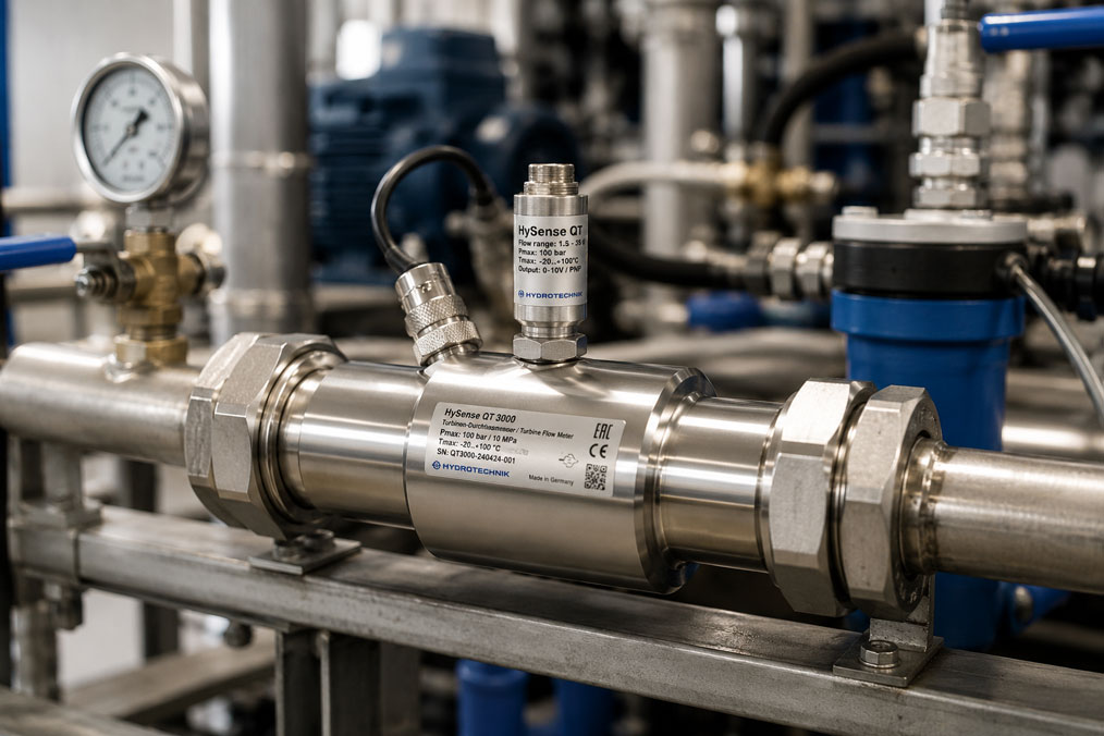
Turbine flow meters are proven flow meters for many liquid media. They provide fast, reproducible signals and are frequently used in hydraulics, test benches, water technology, dosing systems, mechanical engineering and industrial supply lines. However, if a turbine flow meter shows incorrect values, the cause is not always the sensor itself. Very often, measurement deviations are caused by installation errors, air bubbles, contamination, unsuitable inlet runs, incorrect pulse evaluation, viscosity changes or missing calibration.
Especially with turbine flow meters, the interaction between flow, medium, bearings, rotor, signal pickup and evaluation unit is decisive. The turbine does not simply measure “any flow”, but reacts to a defined flow inside the measuring tube. If this flow is disturbed, the rotational behavior of the impeller changes. This can lead to values that are too high, too low, fluctuating or not plausible.
This article explains which causes are particularly common when a turbine flow meter shows incorrect values, how installation, medium and calibration are connected, and why systematic troubleshooting usually leads to the goal faster than immediately replacing the flow meter.
Table of contents
- Basics: how a turbine flow meter measures flow
- Installation errors: inlet run, outlet run and flow profile
- Medium influence: viscosity, density, temperature and operating condition
- Air bubbles, gas content and incompletely filled pipes
- Contamination, particles and mechanical stress
- Flow rate too low or too high
- Pulsation, pressure surges and unstable flow
- K-factor, pulse evaluation and electrical signal testing
- Calibration, reference measurement and documentation
- Practical example: turbine flow meter shows too low a flow rate
- Which measuring instruments / products are suitable?
- Conclusion: incorrect values often originate outside the turbine flow meter
- FAQ: frequently asked questions about incorrect measured values with turbine flow meters
Basics: how a turbine flow meter measures flow
A turbine flow meter measures flow using an impeller that is set into rotation by the flowing medium. The rotational speed of the impeller has a defined relationship to the volumetric flow rate. A sensor detects the rotor movement and usually outputs a pulse or frequency signal. From this signal sequence, an evaluation unit, display, PLC or data logger calculates the current flow rate and often also the total quantity that has passed through.
The measuring principle is very direct and fast. However, it requires the flow to drive the turbine evenly and reproducibly. If the flow profile is disturbed by bends, valves, pumps, reductions or turbulence, the rotational speed of the rotor can change even though the actual flow remains unchanged. This is why installation conditions are particularly important for turbine flow meters.
The medium also influences the measurement result. A turbine flow meter that has been calibrated for a specific medium and viscosity range can deliver deviating values when used with a significantly different viscosity. Temperature changes, gas content, dirt particles, deposits or excessively low flow velocities also have a direct effect on rotational behavior.
During troubleshooting, the complete measuring point should therefore always be considered: measuring range, installation location, medium, operating condition, electrical signal, K-factor, evaluation unit and calibration status. Only when these points are plausible can it be assessed whether the turbine flow meter itself is actually defective.
| Error pattern | Possible cause | First check point |
|---|---|---|
| Measured value too low | Contamination, low flow rate, incorrect K-factor, air content or excessive viscosity | Check flow range, filter condition, medium and evaluation. |
| Measured value too high | Incorrect pulse evaluation, incorrect scaling factor, interference pulses or unfavorable flow profile | Check K-factor, frequency input, wiring and installation environment. |
| Measured value fluctuates strongly | Pulsation, air bubbles, unstable flow, pump influence or signal interference | Check pump, pipe filling, inlet run and signal quality. |
| No signal | Rotor blocked, sensor defective, wiring interrupted or evaluation input incorrectly set | Check mechanical function, power supply, sensor distance and input configuration. |
| Value only fits in one range | Measuring range unsuitable, viscosity influence or calibration not suitable | Compare working range with data sheet and calibration conditions. |
Installation errors: inlet run, outlet run and flow profile
One of the most common causes of incorrect measured values is unfavorable installation. Turbine flow meters require flow that is as even and low-disturbance as possible. Directly after pipe bends, T-pieces, valves, pumps, reductions or expansions, the flow profile is often distorted. The medium then does not strike the impeller evenly, but with swirl, turbulence or an uneven velocity distribution.
Such an installation error can cause the turbine to rotate faster or slower than expected. Control valves, partially opened ball valves, check valves, pump outlets and narrow pipework changes directly upstream of the measuring device are particularly critical. A valve downstream of the turbine flow meter can also influence the flow if it causes pressure fluctuations or feedback effects.
Inlet and outlet runs are therefore not merely theoretical recommendations. They help to create a stable flow profile and make the measurement reproducible. The required length depends on the measuring device, pipe diameter, flow disturbance and manufacturer specifications. If space in the plant is limited, the inlet run should not automatically be shortened. It is better to check technically whether another measuring point, a flow straightener or another measuring principle would make more sense.
The installation position also plays a role. Depending on the design and medium, horizontal or vertical installation may be permissible or preferred. The decisive factors are that the turbine flow meter is completely filled, that no air pockets form and that the rotor is not unfavorably loaded by deposits or gravitational effects. The manufacturer’s specifications for flow direction and installation position should always be followed.
| Installation situation | Possible effect | Practical assessment |
|---|---|---|
| Pipe bend directly upstream of the turbine | Swirl and uneven flow profile | Can lead to systematic measurement deviations. |
| Control valve shortly before the measuring device | Turbulence, pressure fluctuation and strongly altered flow | Particularly critical; create distance wherever possible. |
| Pump outlet directly upstream of the turbine flow meter | Pulsation, vibration and unstable flow | Check calming section or another measuring point. |
| Partially filled pipe | Rotor is not evenly exposed to the medium | Measured value can fluctuate strongly or be completely incorrect. |
| Incorrect flow direction | Rotor operates outside the intended measuring direction | Can lead to no signal or incorrect display. |
Medium influence: viscosity, density, temperature and operating condition
Turbine flow meters react sensitively to the properties of the medium. Viscosity is particularly important. A turbine that has been tested with water or a low-viscosity calibration medium behaves differently when used with oil, glycol mixtures or other more viscous liquids. The flow then transfers its energy differently to the rotor, and friction as well as bearing effects can become more significant.
Viscosity is also temperature-dependent. An oil can be significantly more viscous at low temperature than in warm operating condition. A turbine flow meter can then show values that are too low during system startup, but later appear to measure correctly. If temperature is not taken into account, this behavior quickly looks like a sensor defect, although the medium is the actual cause.
Density and operating pressure can also play a role, especially with media that behave differently under process conditions than in the laboratory or during calibration. With liquids, viscosity is usually the more important influence, but temperature, pressure, gas content and chemical composition should not be ignored.
Special care is required when changing media. If the same turbine flow meter is first used for water and later for oil, solvents or a mixture, the original calibration may no longer be sufficiently suitable. Cleaning media can also dissolve residues or mobilize particles that subsequently influence the rotor or bearings.
Air bubbles, gas content and incompletely filled pipes
Air bubbles are among the most common causes of fluctuating or incorrect values with turbine flow meters. A turbine is generally designed for a completely filled measuring tube with liquid medium. If air or gas content is carried along, the rotor is not driven evenly. The signal can jump, drop out or indicate a flow rate that does not match the actual liquid flow.
Air can enter the measuring section during filling, through leaking suction sides, cavitation, pressure drop, degassing, tank changes or unfavorable pipe routing. Especially at low flow rates and in pipes where the effect is not visible, this influence is often underestimated. The operator only sees fluctuating measured values, while the cause lies in pipe filling.
A partially filled pipe is also critical. If the turbine flow meter is not completely exposed to the medium, the rotor can run unevenly or stop. Measurement in a pipe that is only temporarily fully filled is usually not reliable with a turbine flow meter.
Clean venting of the system, sufficient inlet pressure, suitable pipe routing and a measuring point without air pockets are therefore decisive. In some applications, another flow measuring principle is more suitable if air content or changing pipe filling cannot be safely excluded.
Contamination, particles and mechanical stress
Because a turbine flow meter has moving parts, it reacts particularly sensitively to contamination and particles. Dirt particles can slow down the rotor, damage bearings, restrict mobility or cause uneven running. The result is often values that are too low, fluctuating signals or complete signal failure.
Particles do not always have to originate from the process medium itself. They can also come from installation work, pipe residues, seal residues, corrosion, filter replacement, welding work or deposits in the system. This is why it is particularly important to flush new systems or opened pipelines before commissioning and to check the filter condition.
A filter upstream of the turbine flow meter can be useful, but it must suit the application. A filter that is too fine can cause pressure loss or clog quickly. A filter that is too coarse may not protect the turbine sufficiently. The filter must also be checked regularly. If the filter becomes increasingly clogged, the operating condition of the system changes and the flow measurement can be influenced indirectly.
Mechanical stress caused by vibration, pressure surges or improper installation can also affect the turbine flow meter. The measuring device should be installed free of mechanical stress. Pipe forces, misalignment, high vibration or damaged sealing surfaces can cause long-term problems.
Flow rate too low or too high
Every turbine flow meter has a defined measuring range. Within this range, the relationship between rotor speed and flow rate is reproducible. If the turbine is permanently operated below its minimum flow rate, the flow energy may not be sufficient to drive the rotor stably. The measured value can then be too low, fluctuate or drop out.
A typical error is selecting a turbine flow meter that is too large. It may fit mechanically into the pipeline, but in normal operation it works very low in the measuring range. Especially at part load, with small dosing quantities or intermittent operation, this can lead to unreliable displays. The nominal pipe size is therefore not automatically the correct nominal size of the flow meter.
Excessively high flow is also problematic. If the permissible range is exceeded, the rotor can be mechanically overloaded. Bearings, rotor and signal quality can suffer as a result. Short-term peaks caused by pump startup, valve slam or pressure surge should therefore also be evaluated, not only normal operating flow.
The real working range must be decisive during selection: minimum flow, typical flow, maximum flow, start and stop processes as well as possible pressure peaks. A turbine flow meter should not only fit the theoretical maximum value, but should operate in a stable and suitable range during everyday operation.
Pulsation, pressure surges and unstable flow
Pulsating pumps, piston pumps, dosing pumps, fast-switching valves or compressor influences can cause strong flow fluctuations. A turbine flow meter reacts quickly to such changes. This is generally an advantage, but with unstable flow it can lead to strongly fluctuating measured values.
If the evaluation unit processes the pulses very directly, pressure and flow pulsations can become visible as an apparently changing flow rate. Depending on the application, this is either desired or disturbing. In a control loop, a signal that is too unstable can cause the controller to readjust even though the average flow is sufficiently stable.
Mechanical damping, larger pipe volumes, pulsation dampers, a more suitable measuring point or adapted signal evaluation can help. However, a distinction must be made between real process dynamics and unwanted measurement noise. Excessive electronic smoothing can hide real fast changes.
In dosing applications, it is also important how the flow is evaluated. The instantaneous value can fluctuate strongly, while the total quantity over a defined dosing time is correct. Conversely, faulty pulse detection can lead to incorrect total values. For this reason, instantaneous value, total quantity and pulse processing must be checked together.
K-factor, pulse evaluation and electrical signal testing
The K-factor describes how many pulses a turbine flow meter generates per volume unit. It is the basis for calculating a flow value or total quantity from the sensor signal. If the wrong K-factor is stored in the evaluation unit, the system displays incorrect values even though the turbine flow meter works mechanically without fault.
Typical errors are caused by incorrect units, incorrect decimal point, incorrect scaling, confusion between liters and cubic meters or the use of a standard value instead of the calibrated K-factor. Especially after replacing a turbine flow meter, sensor or display, the K-factor should be checked. Two externally similar turbine flow meters can have different calibration values.
The electrical pulse evaluation must also match the turbine flow meter. Sensor type, signal level, supply voltage, frequency range, input resistance, debouncing, counting direction and filter settings can influence the result. If a fast pulse generator is connected to an input that is too slow, pulses can be lost. If a sensitive input is not wired cleanly, interference pulses can be counted.
If the turbine signal is additionally output as a 4–20 mA signal via a transmitter, this current loop should also be checked. The UPS4E loop calibrator is suitable for this. It can be used to measure and simulate mA signals, allowing scaling errors between flow transmitter, display, PLC or data logger to be identified more quickly.
| Check point | Possible error | Typical effect |
|---|---|---|
| K-factor | Incorrect value or incorrect unit stored | Flow and total quantity are calculated systematically incorrectly. |
| Pulse input | Input does not count all pulses or counts interference pulses | Display is too low, too high or unstable. |
| Frequency range | Maximum input frequency is exceeded | Pulses are lost at high flow rates. |
| Wiring | Shielding, ground reference or cable length unfavorable | Signal interference or implausible jumps in the measured value. |
| 4–20 mA output | Transmitter and PLC scaled differently | The electrical signal is plausible, but the displayed flow rate is incorrect. |
Calibration, reference measurement and documentation
A turbine flow meter should be calibrated to match the application. Calibration establishes the relationship between real flow and output signal. The K-factor is determined or verified in the process. Depending on requirements, factory calibration, traceable calibration or application-oriented calibration with comparable operating conditions can be useful.
The key question is whether the calibration conditions match the real application. If a turbine was calibrated with water but later measures a significantly viscous oil, the deviation can be greater than expected. Temperature, flow range and installation situation can also influence practical values. For high accuracy requirements, it should therefore be checked whether medium or viscosity adjustment is required.
A reference measurement can help narrow down errors. The turbine flow meter is compared with a suitable reference measuring instrument or a known volume over a defined time. It is important that the reference measurement itself is carried out cleanly. An inaccurate container, changing temperature, air content or an unstable pump can otherwise lead to incorrect conclusions.
Documentation should include K-factor, calibration date, measuring range, medium, installation position, evaluation unit, scaling and any correction factors. This is particularly important when several turbine flow meters are in use or devices are replaced regularly. Without clear documentation, troubleshooting often takes unnecessarily long.
Practical example: turbine flow meter shows too low a flow rate
In a test bench, the flow of a low-viscosity oil is monitored with a turbine flow meter. After maintenance, the display shows significantly lower values than before. The pump runs normally, the pressure is plausible and the medium is unchanged. Initially, a defect in the turbine flow meter is suspected.
During inspection, it becomes apparent that a filter upstream of the turbine flow meter was replaced. In addition, the pipe was opened. After restart, small air bubbles are still present in the system. At the same time, the new filter is finer than the previous filter and causes a higher pressure loss. As a result, the flow at the measuring point is more unstable than before maintenance.
The turbine flow meter itself moves freely mechanically. The K-factor is correctly stored in the evaluation unit. After thorough venting, checking the filter and stabilizing the operating condition, the measured values are again within the expected range. Replacing the turbine flow meter was not necessary.
This example shows that incorrect values are often caused by changes in the system environment. Maintenance, filters, air bubbles, changed operating conditions or new scaling can influence the measured value without the sensor itself being damaged.
Which measuring instruments / products are suitable?
For applications with turbine flow meters, ICS Schneider Messtechnik offers the category turbine flow meters. There you will find solutions for different flow ranges and industrial applications where a fast pulse or frequency signal is required for flow rate and total quantity.
The higher-level category flow measurement technology is useful when checking whether a turbine flow meter is truly the right measuring principle for the application. In the case of air bubbles, highly viscous media, abrasive media, hygienic requirements or incompletely filled pipes, another measuring method may be more suitable depending on the process.
If a turbine flow meter is operated with an evaluation unit, frequency input, counter, data logger or transmitter, the entire signal chain should be considered. In addition to the mechanical inspection of the rotor, K-factor, pulse counting, frequency range, wiring, shielding and scaling are decisive. For 4–20 mA outputs, the UPS4E loop calibrator also helps to check the current loop and PLC scaling.
The most important recommendation is: do not select turbine flow meters only by nominal pipe size. The actual flow range, medium, viscosity, temperature, pressure, installation position, inlet run, particle load, required signal and calibration requirement are decisive.
| Product / area | Typical use | Particularly relevant for |
|---|---|---|
| Turbine flow meters | Turbine flow measurement with pulse or frequency signal | Hydraulics, test benches, water technology, dosing, mechanical engineering and industrial media |
| Flow measurement technology | Selection of the suitable flow measuring principle | Media comparison, difficult installation conditions, alternative measuring methods and process consulting |
| Counter / evaluation unit | Acquisition of pulses, frequency, instantaneous value and total quantity | K-factor, dosing, totalizer, test benches and system control |
| Reference measuring instrument / calibration | Reference measurement and verification of measurement deviation | Quality assurance, test equipment monitoring, fault analysis and recurring inspection |
| UPS4E loop calibrator | Testing of 4–20 mA signals at transmitters | PLC scaling, commissioning, replacement and troubleshooting on analog signal outputs |
Conclusion: incorrect values often originate outside the turbine flow meter
If a turbine flow meter shows incorrect values, a sensor defect should not be assumed immediately. Causes are often related to installation, medium, flow profile, air bubbles, contamination, pulsation, incorrect K-factor or faulty pulse evaluation. Because turbine flow meters react quickly and directly to flow changes, they often make process disturbances very clearly visible.
Reliable troubleshooting therefore starts with the overall system: Is the pipe completely filled? Are there sufficient inlet runs? Is the medium clean and within the correct viscosity range? Is the turbine operating in the appropriate flow range? Are the K-factor and evaluation unit correct? Are there air bubbles, pulsation or interference pulses?
The most important recommendation is: always consider turbine flow meter, installation situation, medium and evaluation together. Only once these points have been checked can it be safely decided whether cleaning, recalibration, adjustment of the evaluation, change of measuring point or a different flow measuring principle is required.
FAQ: frequently asked questions about incorrect measured values with turbine flow meters
Why does my turbine flow meter show incorrect values?
Common causes include incorrect installation, inlet runs that are too short, air bubbles, contamination, particles, incorrect K-factor, unsuitable flow range, viscosity changes or errors in pulse evaluation. The sensor itself is not always defective.
What role does the inlet run play with a turbine flow meter?
The inlet run provides a more stable flow profile upstream of the measuring device. If a pipe bend, valve, T-piece or pump outlet is located directly upstream of the turbine, the flow can be disturbed and the turbine can deliver incorrect values.
Can a turbine flow meter measure correctly with air bubbles?
Usually only to a limited extent. Turbine flow meters for liquids require a completely filled measuring tube. Air bubbles or gas content can drive the rotor unevenly and lead to fluctuating or incorrect measured values.
Why does the turbine flow meter show too little at low flow rates?
Below the minimum flow rate, the flow energy may not be sufficient to drive the rotor stably. The measured value can then be too low, fluctuate or drop out completely. The turbine should be operated in the appropriate working range.
What is the K-factor of a turbine flow meter?
The K-factor indicates how many pulses the turbine flow meter generates per volume unit. It is the basis for calculating flow and total quantity. An incorrectly set K-factor leads to systematically incorrect measured values.
Why is the viscosity of the medium important?
Viscosity influences how the medium drives the rotor. At higher viscosity, friction and flow behavior can change the measurement. Especially with oil or temperature-dependent media, calibration should match the application.
Can temperature influence turbine flow meter measurement?
Yes. Temperature often changes the viscosity of the medium. An oil can be significantly more viscous during system startup than during warm operation. As a result, the turbine flow meter may initially show different values than later in stable condition.
What happens with contamination or particles?
Particles can slow down the rotor, damage bearings or restrict mobility. This often leads to values that are too low, fluctuating signals or failure of the sensor signal. Filters and clean pipelines are therefore important.
Can a filter upstream of the turbine flow meter cause problems?
A filter can protect the turbine flow meter, but it can also cause pressure loss or change the operating condition if clogged. The filter must suit the application and be checked regularly.
Why does the measured value fluctuate strongly?
Strong fluctuations are often caused by pulsation, air bubbles, pump influence, unstable flow or electrical interference pulses. Signal evaluation that is too direct or unsuitable can also amplify fluctuations.
How can I recognize incorrect pulse evaluation?
Indications include systematically too high or too low values, implausible total values, jumps or deviations only at high flow rates. K-factor, input frequency, signal level, wiring and counter settings should be checked.
When should a turbine flow meter be calibrated?
Calibration is useful during commissioning, after cleaning or repair, if measured values are conspicuous, after a change of medium, at fixed inspection intervals or if the measuring point is quality-relevant. The real operating range should be considered wherever possible.
Can a turbine flow meter be used with any medium?
No. The medium must match the turbine. Viscosity, particles, chemical compatibility, lubricity, temperature, pressure and gas content must be considered. With unsuitable media, another measuring principle may be better.
Why is nominal pipe size not the only decisive factor?
The turbine flow meter must match the actual flow range, not only the pipe size. A turbine that is too large can operate below its optimum measuring range during normal operation and therefore deliver unreliable values.
How can you check whether the turbine flow meter or the system is the problem?
A systematic check of pipe filling, air bubbles, installation, filter, medium, flow range, K-factor, signal and reference measurement is useful. If these points are correct and the error remains, the turbine flow meter should be checked mechanically and by calibration.
When is another flow measuring principle better?
Another measuring principle can be useful if the medium is heavily contaminated, very viscous, abrasive, gas-loaded or if the pipe is not reliably completely filled. An alternative should also be checked for very low flow rates or unfavorable installation conditions.