


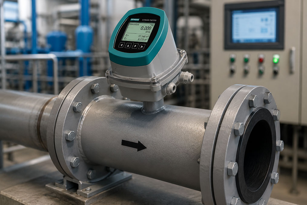
If a magnetic-inductive flow meter, or MID for short, shows no flow, a defect in the device is often suspected first. In practice, however, the cause is very often not the transmitter or sensor itself, but the operating conditions: the pipe is not completely filled, the medium is not sufficiently conductive, the electrodes are not wetted, air bubbles interfere with the measurement, grounding is missing or a parameter in the transmitter suppresses small flow rates.
MID flow meters are very reliable in many applications when the basic conditions are correct. They require an electrically conductive medium, a completely filled measuring tube, clean electrode wetting and correct equipotential bonding. If these requirements are not met, the flow meter may display zero even though something is actually moving in the pipe.
This article explains how troubleshooting can be structured systematically. It covers typical causes such as empty piping, incorrect installation position, insufficient conductivity, air in the medium, wrong flow direction, sensor and transmitter parameters, empty pipe detection, low-flow cut-off and signal processing. The goal is not to replace components immediately, but to narrow down the fault step by step.
Table of contents
- Basics: why a MID only measures under certain conditions
- Clarify the fault pattern: zero display, fluctuating value or diagnostic message?
- Is the pipe completely filled? The most common practical error
- Check minimum conductivity and electrode wetting
- Grounding, equipotential bonding and interference signals
- Installation position, flow direction and air bubbles
- Parameterization: SENSORPROM, measuring range, low-flow cut-off and outputs
- Signal check: when the MID measures, but the PLC shows nothing
- Practical example: MID shows 0 m³/h after pump conversion
- Which measuring instruments / products are suitable?
- Conclusion: check process conditions first, then evaluate device replacement
- FAQ: frequently asked questions when a MID shows no flow
Basics: why a MID only measures under certain conditions
A magnetic-inductive flow meter works according to the inductive measuring principle. Put simply, a magnetic field is generated in a measuring tube. When an electrically conductive liquid moves through this magnetic field, a voltage is generated that is proportional to the flow velocity. Electrodes in the measuring tube pick up this signal, and the transmitter calculates the volumetric flow from it.
This principle leads to important requirements. The medium must be electrically conductive. The electrodes must be wetted by the medium. The measuring tube must be completely filled so that the device can record a stable, representative flow. In addition, sensor, transmitter, grounding, connection cable and parameterization must match.
A MID therefore does not simply measure every movement in the pipe. Pure oil, many hydrocarbons, gases, steam or liquids with very poor conductivity are not suitable for this measuring principle. Even with generally suitable media, problems can occur if air bubbles, partial filling, deposits or missing equipotential bonding interfere with the measuring signal.
For this reason, the most important rule in troubleshooting is: a zero display does not automatically mean that no medium is flowing, and it also does not automatically mean that the flow meter is defective. First, it must be checked whether the physical and electrical requirements for MID measurement are fulfilled.
| Requirement | Why important? | Typical error if ignored |
|---|---|---|
| Completely filled pipe | Only a filled measuring tube enables stable electrode wetting and a representative signal. | MID shows 0, jumps or reports an empty pipe. |
| Sufficient conductivity | The measuring principle requires an electrically conductive medium. | No stable measurement with unsuitable or poorly conductive liquids. |
| Electrode wetting | The electrodes must be in contact with the medium. | Partial filling, air pockets or deposits lead to incorrect values. |
| Grounding / equipotential bonding | Stable reference potentials are important for small measuring signals. | Unstable values, zero display or interference due to external potentials. |
| Correct parameterization | Sensor, transmitter, measuring range and outputs must match. | Transmitter measures, but display, output or PLC show incorrect values or 0. |
Clarify the fault pattern: zero display, fluctuating value or diagnostic message?
Before a MID is removed or a transmitter is replaced, the fault pattern should be described precisely. Does the device permanently show 0? Does the value fluctuate strongly? Is there a diagnostic message such as empty pipe, electrode fault, sensor fault or output fault? Do totalizers and display work, but the signal to the PLC is missing?
A permanent zero display can be caused by actual standstill, an empty pipe, a non-conductive medium, wrong flow direction, incorrectly set low-flow cut-off or unsuitable parameterization. A strongly fluctuating value is more likely to indicate air bubbles, partial filling, pump pulsation, poor grounding or interference.
If the transmitter displays diagnostic information, this message should be taken seriously. Modern devices often detect empty pipe, sensor interruption, coil fault, electrode problems or communication errors. Diagnostics do not replace professional evaluation, but they provide valuable indications of whether the fault is more likely to be in the process, the sensor, the wiring or the parameterization.
The timing of the fault is also important. Did the zero display occur after cleaning, a pump conversion, a sensor replacement, a change to the transmitter or after a longer shutdown? Such information is often decisive. After modifications, the cause is often installation position, flow direction, wiring or parameterization. After shutdown, deposits, air pockets or dry electrodes may play a role.
Is the pipe completely filled? The most common practical error
A MID requires a completely filled measuring tube. This sounds simple, but in practice it is one of the most common causes of zero displays or implausible values. Especially in horizontal lines, falling pipe sections, suction lines, partially filled wastewater lines or systems with intermittent operation, the sensor may partly run empty.
If the measuring tube is only partially filled, the electrodes may not be fully wetted. Depending on the installation position, air can collect in the upper area while liquid flows below. The flow meter then appears to be installed in a pipe containing medium, but in reality it is not in a stable filled measuring condition. The device can then display 0, fluctuate strongly or issue an empty pipe message.
Installation points at high points of the pipeline are particularly critical. Air bubbles and gas pockets collect there. The flow can also be disturbed directly downstream of pumps, valves or bends. In vertical lines, a flow direction from bottom to top is often more favorable because the measuring tube is more likely to remain completely filled.
During troubleshooting, it is therefore not enough to ask whether medium is present somewhere. It must be checked whether the sensor is actually completely filled during operation. Visible pipe routing, venting, pump operation, valve position and operating states must be considered together.
Check minimum conductivity and electrode wetting
The magnetic-inductive measuring principle only works with electrically conductive liquids. Water, wastewater, many aqueous solutions, acids, alkalis, sludges and numerous process media are generally suitable. Gases, steam, mineral oils, fuels and many organic solvents, on the other hand, are not suitable if their conductivity is too low.
If a medium change has taken place, the conductivity should definitely be checked. A system may have measured reliably with an aqueous medium, but after switching to another product it may no longer provide stable MID measurement. The flow is then actually present, but the measuring principle does not receive a sufficiently usable signal.
Electrode wetting is also important. Even with sufficient conductivity, the measurement can fail if electrodes are dry, dirty, insulated or covered with deposits. Deposits, grease films, crystallization, coatings or air pockets can impair the contact between medium and electrode.
For media that tend to form deposits, it should be checked whether the electrodes need to be cleaned, whether the installation point is unfavorable or whether another sensor type or material version is better suited. In some applications, cleaning cycles, flushing options or a different process setup are necessary to keep the measurement stable in the long term.
| Medium / condition | Typical MID suitability | Practical assessment |
|---|---|---|
| Water and wastewater | Usually well suited | Pipe filling, air bubbles, grounding and deposits remain relevant. |
| Aqueous chemicals, acids and alkalis | Often suitable, depending on conductivity and materials | Check media compatibility of liner and electrodes. |
| Sludges and suspensions | Often suitable if conductive and sufficiently homogeneous | Pay particular attention to deposits, electrode coating and installation position. |
| Oils, fuels, many solvents | Usually not suitable | Conductivity too low; check another measuring principle. |
| Gas or steam | Not suitable | MID does not measure gaseous media; check vortex, Coriolis, differential pressure or other methods. |
Grounding, equipotential bonding and interference signals
A MID processes very small measuring signals. Grounding and equipotential bonding are therefore not just formal installation details, but important prerequisites for stable measurement. The sensor and the medium require a defined reference potential. Especially with plastic pipes, lined pipes or insulating pipe sections, it must be checked how equipotential bonding is established.
If grounding is missing or equipotential bonding is poorly implemented, interference voltages can affect the measuring signal. This can lead to unstable measured values, zero display, error messages or implausible jumps. Pumps, frequency converters, large motors or nearby power cables can also introduce interference if cable routing and shielding are unfavorable.
In metallic pipelines, equipotential bonding is often easier to establish, provided the pipe connections are conductive and correctly integrated. With plastic pipes or coated pipes, grounding rings, grounding electrodes or special grounding concepts are used depending on the sensor and manufacturer specifications. The specific implementation must always follow the manufacturer’s instructions.
During troubleshooting, it should therefore be checked whether grounding cables are present, correctly connected and mechanically intact. Corroded connections, loose screws, painted contact surfaces or pipe sections modified later can influence the measurement, even if the sensor itself is technically in good condition.
Installation position, flow direction and air bubbles
The installation position largely determines whether a MID provides stable values. A sensor should be installed so that the pipe remains completely filled during operation and air bubbles do not continuously pass the electrodes or remain there. With horizontal installation, the electrodes should typically be positioned laterally so that they are neither unfavorably located in an air pocket at the top nor in the sediment area at the bottom.
The flow direction must also be correct. Many MID systems can detect forward and reverse flow or can be parameterized accordingly. If the sensor has been installed against the expected flow direction or the transmitter only evaluates one direction, the displayed value may be 0 or negative, or may be suppressed by output parameters.
Air bubbles are another common cause. They can result from leaking suction lines, degassing of the medium, pump operation, strong pressure changes or insufficient venting. Small amounts of air often lead to fluctuating values, while larger gas pockets can completely disturb the measurement. Especially during commissioning after draining, the line must be vented carefully.
Flow profile and straight inlet runs can also play a role depending on the sensor design. Directly downstream of bends, T-pieces, pumps, control valves or reducers, the flow can be uneven. A MID is often more tolerant than some mechanical measuring principles, but the installation point should still not be selected without considering the pipe routing.
Parameterization: SENSORPROM, measuring range, low-flow cut-off and outputs
If process conditions and installation are basically correct, parameterization becomes the focus. In MID systems, sensor and transmitter must match each other. Sensor size, calibration factor, measuring range, flow direction, units, empty pipe detection, limits and output assignment must be set correctly.
In Siemens MAG systems, SENSORPROM plays an important role. Sensor data can be stored in the memory and transferred to the transmitter. This simplifies commissioning and replacement, but it does not replace checking the overall configuration. Especially after replacing a transmitter or sensor, it should be checked whether the transferred values are plausible and match the actual installation situation.
A frequently overlooked setting is low-flow cut-off. It prevents very small flows, noise or residual movements from being displayed or counted as real flow. This is useful, but if set incorrectly, it can cause a real small flow to be displayed as 0. This parameter is particularly important for dosing, small pipe sizes, leakage quantities or start-up operation.
The output parameters can also create the impression that no flow is present. The transmitter may display a value locally, while a current output, pulse output, relay or bus signal is not correctly parameterized. Therefore, a clear distinction should always be made between “the transmitter measures nothing” and “the higher-level system receives no signal”.
| Parameter / function | Possible error | Effect |
|---|---|---|
| Sensor size / calibration factor | Incorrect sensor data or wrong sensor type set | Flow value is incorrectly scaled or implausible. |
| Flow direction | Sensor installed against the parameterization | Value becomes negative, 0 or is not output as expected. |
| Low-flow cut-off | Limit set too high | Small real flows are displayed as 0. |
| Empty pipe detection | Incorrectly activated, incorrectly set or process not completely filled | Measurement is blocked or diagnostic message appears. |
| Outputs / communication | Current output, pulse value or bus address incorrectly set | Local display is correct, but PLC or counter shows no flow. |
Signal check: when the MID measures, but the PLC shows nothing
An important distinction in troubleshooting is the question of where the flow is not displayed. Does the transmitter itself show 0? Or does the transmitter show a plausible value while the PLC, control system, data logger or counter displays no flow? In the second case, the cause is often not in the MID measuring principle, but in signal transmission or scaling.
For current outputs, the output range must match the PLC scaling. For pulse outputs, pulse value, pulse width, input type and counting direction must be set correctly. For relay functions, it must be clear whether the relay is parameterized as a limit value, fault contact, flow indication or dosing function. For digital interfaces, address, protocol, baud rate, data format and communication logic are also relevant.
If a MID is connected to a PLC or display via a 4–20 mA signal, the current loop should be checked separately. The UPS4E loop calibrator is a suitable tool for this. It can measure and simulate mA signals, power current loops and identify scaling errors at PLC analog inputs or displays. This makes it possible to determine whether the fault is in the MID, the wiring or the target system.
For bus communication, the local display and diagnostics on the transmitter should be checked first. If a plausible flow is present there but no data arrives in the control system, communication parameters, device address, bus wiring, terminating resistors, mapping and evaluation unit are the next points to check.
Practical example: MID shows 0 m³/h after pump conversion
In a water system, a pump is replaced. After commissioning, the magnetic-inductive flow meter in the control system shows 0 m³/h, even though the pump is running and movement in the system is visible elsewhere. Initially, it is suspected that the MID sensor is defective or that the transmitter is no longer working correctly.
During the check, it first becomes apparent that the transmitter does not issue a clear device fault message. The local display fluctuates briefly, but repeatedly falls back to 0. The low-flow cut-off is not set noticeably high, and the PLC scaling has not been changed. This shifts the focus more strongly to the process itself.
An inspection of the pipe routing shows that the operating conditions have changed due to the pump conversion. The MID is now located at a point where air collects under certain valve positions. After start-up, the measuring tube is not permanently completely filled. The electrodes are sometimes not properly wetted, and empty pipe detection blocks the measurement.
After venting the line and adapting the operating procedure, the MID again shows stable values. In addition, the installation situation is evaluated so that the fault does not recur during future start-up procedures. The sensor was not defective. The cause was pipe filling, air pockets and changed process conditions after the conversion.
Which measuring instruments / products are suitable?
For magnetic-inductive flow measurement, ICS Schneider Messtechnik offers the category magnetic-inductive flow meters / MID. It includes various MID solutions for conductive liquids, water, wastewater, process media and industrial applications. Decisive selection criteria are medium, conductivity, nominal diameter, liner, electrode material, installation situation, measuring range and desired communication.
The MAG5000 / MAG6000 transmitters are suitable for magnetic-inductive flow measurement with Siemens SITRANS FM sensors. They are particularly relevant when proven MAG systems with display, diagnostics, totalizers, SENSORPROM and various output or communication options are to be used. During troubleshooting and replacement, it is important to properly compare sensor and transmitter data.
The SITRANS FMT020 transmitter is particularly interesting when, in addition to volumetric flow and flow velocity, electrical conductivity, modern diagnostic functions and empty pipe detection also play a role. Especially with the fault pattern “MID shows no flow”, diagnostic functions can help distinguish between empty pipe, process problem and device problem.
If the MID is integrated into a PLC, display or data logger via an analog 4–20 mA signal, the electrical signal processing should also be checked. The UPS4E loop calibrator supports troubleshooting in current loops by measuring and simulating mA signals and making it possible to check the scaling of the target system.
| Product / area | Typical use | Particularly relevant for |
|---|---|---|
| Magnetic-inductive flow meters / MID | Selection of suitable MID systems for conductive liquids | Water, wastewater, process media, chemicals, industry and utility systems |
| MAG5000 / MAG6000 transmitters | Transmitters for Siemens SITRANS FM MAG systems | SENSORPROM, diagnostics, totalizers, display, classic MAG systems and replacement cases |
| SITRANS FMT020 transmitter | Modern MID transmitter for volumetric flow, flow velocity and conductivity | Empty pipe detection, device self-test, modern communication and commissioning |
| UPS4E loop calibrator | Testing and simulation of 4–20 mA signals | PLC scaling, analog output, current loop, commissioning and troubleshooting |
Conclusion: check process conditions first, then evaluate device replacement
If a MID shows no flow, a defective sensor or transmitter should not be assumed immediately. The causes are often found in the application itself: the pipe is not completely filled, air bubbles interfere with the measurement, the medium is not sufficiently conductive, electrodes are not wetted, grounding is missing or parameters such as low-flow cut-off and output assignment are not set appropriately.
The most important recommendation is: always build troubleshooting from the process toward the electronics. First check pipe filling, medium, conductivity, installation position, flow direction and air in the system. Then evaluate grounding, equipotential bonding, sensor cables and diagnostic messages. Only after that should parameterization, outputs, communication and PLC scaling be checked.
Modern transmitters such as MAG5000 / MAG6000 or SITRANS FMT020 support diagnostics with display, sensor data, empty pipe detection, self-test and communication functions. Nevertheless, professional evaluation remains decisive: a MID can only measure reliably when measuring principle, process conditions and parameterization match.
FAQ: frequently asked questions when a MID shows no flow
Why does my MID show no flow?
Common causes include an incompletely filled pipe, insufficient conductivity of the medium, missing electrode wetting, air bubbles, wrong flow direction, missing grounding, incorrect parameterization, activated empty pipe detection or low-flow cut-off set too high.
Can a MID show 0 even though medium is flowing?
Yes. If the measuring tube is partially empty, air bubbles pass the electrodes, the medium is not sufficiently conductive or the flow is below the low-flow cut-off, the MID may show 0 despite actual movement.
Why must the pipe be completely filled for a MID?
The MID requires stable electrode wetting and a fully flowed-through measuring tube. With partial filling, the electrical signal can be disturbed or not representative. This leads to zero display, fluctuating values or empty pipe messages.
Which media are suitable for MID?
Electrically conductive liquids are suitable, for example water, wastewater, many aqueous solutions, acids, alkalis, sludges and suspensions. Gases, steam, oils, fuels and many poorly conductive solvents are not suitable.
What does minimum conductivity mean for MID?
Minimum conductivity describes how conductive a medium must be at least so that the magnetic-inductive measuring principle can generate a usable signal. The specific limit depends on the device, sensor and manufacturer and must be checked in the data sheet.
What role do the electrodes play?
The electrodes pick up the measuring signal from the conductive medium. If they are not wetted, dirty, insulated or covered with deposits, the signal can be disturbed. As a result, the MID shows incorrect values, fluctuating values or no flow.
Why is grounding so important for MID?
The MID measures small electrical signals. Without stable equipotential bonding, interference voltages, external potentials or EMC influences can falsify the measurement. Especially with plastic pipes or lined pipes, the grounding concept must be implemented carefully.
What is empty pipe detection?
Empty pipe detection recognizes whether the measuring tube is not sufficiently filled with medium. Depending on the device, the measurement can then be blocked or a diagnostic message can be issued. This prevents implausible partial filling values from being interpreted as real flow.
Why does the MID show no flow after start-up?
After start-up, air pockets, incompletely filled lines, closed valves, wrong pump direction or unfavorable operating states may occur. Only when the line is completely filled and vented can the MID measure stably.
What is low-flow cut-off?
Low-flow cut-off suppresses very small flows or signal noise. It is useful, but if set incorrectly, it can cause small real flows to be displayed as 0. Therefore, the parameter must match the application.
Can the flow direction influence the display?
Yes. If the sensor is installed against the expected direction or the evaluation only considers one flow direction, the value can be negative, 0 or not output as expected. Flow direction and parameterization should therefore be checked.
Why does the local display show flow, but the PLC shows 0?
In that case, the MID is probably measuring in principle, but signal transmission is not correct. Causes can include incorrect output parameterization, incorrect PLC scaling, wiring faults, wrong pulse value, communication problems or an incorrectly assigned analog input.
How do you test the 4–20 mA output of a MID?
The current output can be tested with a loop calibrator or suitable measuring instrument. The mA value is compared with the local display. In addition, defined mA values can be simulated to check PLC scaling independently of the MID.
Can a MID show incorrect values due to air bubbles?
Yes. Air bubbles disturb electrical signal pickup and the flow in the measuring tube. Small air fractions often lead to fluctuating values, while larger air pockets can cause zero display or empty pipe messages.
What should be checked after replacing a sensor or transmitter?
After replacement, sensor data, calibration factor, nominal diameter, flow direction, measuring range, units, empty pipe detection, output parameters and communication should be checked. In systems with SENSORPROM, it should be verified whether the transferred data plausibly matches the installation.
When should the MID be removed or replaced?
Removal or replacement should only be considered once process conditions, pipe filling, conductivity, grounding, electrode condition, wiring, diagnostic messages and parameterization have been checked. Only if these points reveal no cause is a device fault more likely.