


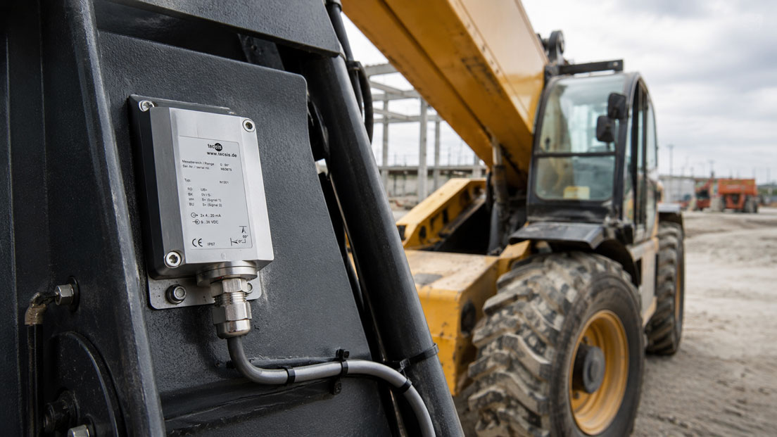
Mobile machines rarely operate on perfectly level ground. Construction machines, cranes, aerial work platforms, agricultural machines, municipal vehicles and mobile hydraulic systems move across construction sites, fields, unpaved roads, ramps or changing working positions. In these situations, the inclination of the machine, chassis, boom or work platform quickly becomes an important measured variable.
Tilt sensors detect the position of a component relative to gravity. For example, they can indicate whether a vehicle is level, whether a boom has reached a critical angle, whether a work platform is levelled or whether a machine is operating in an unstable position. This makes tilt sensors key components for mobile working machines where stability, ease of operation, positioning and safety functions play an important role.
For tilt monitoring to work reliably, the sensor, measuring range, mounting position, signal type, control system, filtering and safety concept must all be matched correctly. In mobile machines in particular, vibrations, shocks, temperature changes, moisture, dirt and dynamic movements affect the measurement. This article explains what to consider when selecting and integrating tilt sensors in mobile machines.
Table of contents
- Why tilt sensors are important in mobile machines
- What does a tilt sensor measure?
- Typical applications: booms, platforms, chassis and attachments
- Selecting the right measuring range, number of axes and resolution
- Mounting position and mechanical integration
- Zero point, reference position and calibration
- Taking vibrations, shocks and dynamic movements into account
- Temperature drift and environmental conditions
- Output signals: 4–20 mA, 0–10 V, CANopen and SAE J1939
- Tilt sensors in safety functions
- Tilt monitoring in mobile hydraulic systems
- Commissioning and troubleshooting
- Practical example: Tilt monitoring on an aerial work platform
- Which measuring instruments / products are suitable?
- Conclusion: Measure tilt accurately, but always assess it within the overall system
- FAQ: Frequently asked questions about tilt sensors in mobile machines
Why tilt sensors are important in mobile machines
In mobile machines, the position of the vehicle or a moving machine component is often directly linked to operational safety. A crane operating on inclined ground has different stability reserves than the same crane on level ground. An aerial work platform must know whether the platform is levelled. An agricultural machine must guide attachments, booms or working tools in a defined position. A mobile machine with a boom must detect whether the working range is still permissible.
Tilt sensors provide continuous information about the angle. This information can be displayed, documented, transmitted to a control system or used as part of a monitoring function. Depending on the application, the measurement is used for operator information, automatic levelling, working range limitation, load moment monitoring or the prevention of critical machine positions.
It is particularly important to distinguish between a pure display function and a safety-related function. A tilt sensor can provide the operator with position information. However, if this information results in a safety-relevant intervention, such as movement limitation or shutdown, the complete safety concept must be considered. This includes the sensor, control system, software, actuators, diagnostics and the required safety assessment.
The benefit of a tilt sensor therefore lies not only in the measured value itself. What matters is how the measured value is used within the machine. Precise tilt measurement can make operation easier, improve process quality, reduce incorrect operation and help detect critical states at an early stage.
| Application | Typical measuring task | Benefit in the machine |
|---|---|---|
| Aerial work platform | Detect platform tilt and chassis tilt | Levelling, warning and working range monitoring. |
| Crane / loader crane | Measure boom angle and vehicle position | Stability, load moment assessment and movement limitation. |
| Construction machine | Detect tilt of chassis, bucket, blade or boom | Positioning, operator support and machine control. |
| Agricultural machine | Monitor the position of booms, attachments or vehicle frame | Work quality, automatic adjustment and comfort functions. |
| Mobile hydraulics | Detect angular position of hydraulically moved components | Control, limit monitoring and diagnostics. |
What does a tilt sensor measure?
A tilt sensor measures the angle of a component relative to gravity. A MEMS-based measuring principle is often used for this purpose. The sensor detects the acceleration caused by the earth’s gravity and calculates the tilt from it. Depending on the sensor, tilt can be measured in one axis or in two axes.
A single-axis tilt sensor measures inclination in one defined direction. This is useful when movement only needs to be evaluated around one main axis, for example on a boom, folding mechanism or pivoting component. A dual-axis sensor measures two perpendicular tilt directions and is suitable, for example, for chassis levelling or platform monitoring.
The measurement always refers to the mounting position of the sensor. If the sensor is mounted at an angle or mechanically stressed, the zero point shifts. This is why the mechanical reference is just as important as the electrical evaluation. A good sensor can deliver incorrect values if it is mounted in an unsuitable position or in the wrong orientation.
It is also important to understand that a tilt sensor measures static position particularly well. During fast movements, strong vibrations or shocks, additional accelerations may occur that do not come from gravity but from machine movement. These dynamic influences must be taken into account in mobile machines.
Typical applications: booms, platforms, chassis and attachments
A common application is boom monitoring. On cranes, excavators, telehandlers, concrete pumps or aerial work platforms, the boom angle changes the reach, load distribution and stability of the machine. The tilt sensor can help detect the current angle and integrate it into a control or monitoring function.
For work platforms, the focus is often on levelling and operator safety. The platform should remain within a permissible angular range, even if the ground or boom position changes. A tilt sensor can monitor the platform position and report to the control system whether correction or warning is required.
The chassis of a mobile machine can also be monitored. If a machine is standing on a slope, ramp or uneven ground, its stability changes. Chassis tilt can serve as an input value for warning displays, lockout functions, load moment limitations or automatic levelling systems.
In agriculture and municipal technology, tilt sensors are frequently used for attachments, mowers, spray booms, snow blades or other working tools. The measurement supports a uniform working position and can help improve ground following, work quality and operating comfort.
| Machine component | Typical tilt measurement | Special challenge |
|---|---|---|
| Boom | Angle relative to the horizontal or to the machine frame | Dynamics, load changes and mechanical vibration. |
| Work platform | Tilt in longitudinal and transverse direction | Stable display despite movement and personnel load. |
| Chassis | Machine position on uneven ground | Distinguishing between static position and driving movement. |
| Attachment | Position of the working tool | Dirt, impacts, vibration and changing mounting points. |
| Hydraulic arm | Position of a moving component | Filtering, repeatability and mechanical protection. |
Selecting the right measuring range, number of axes and resolution
The measuring range must match the application. Smaller angular ranges are often required for chassis levelling than for a boom operating over a wide angular range. A measuring range that is too small can be exceeded in limit positions. A measuring range that is too large, on the other hand, can reduce the usable resolution in the area of interest.
When selecting a sensor, it is therefore important not only to consider the maximum angle, but also the working range in which the measurement must be particularly accurate. If a machine is only levelled between -10° and +10°, a sensor with a very large measuring range is not automatically better. For booms or pivoting mechanisms, however, a larger range may be required.
The number of axes depends on the direction of movement. A single-axis sensor is sufficient if only one defined tilting movement is relevant. A dual-axis sensor is useful when longitudinal and transverse tilt must be monitored simultaneously. For platforms, vehicle frames or chassis monitoring, dual-axis measurement is often particularly helpful.
Resolution and accuracy are often confused. Resolution describes how finely an angular change can be detected in the signal. Accuracy describes how close the displayed value is to the actual angle. For good machine function, both must match the application. A very fine display is of little use if mounting errors, temperature drift or vibrations dominate the actual measured value.
Mounting position and mechanical integration
The mounting position has a major influence on the significance of the measurement. A tilt sensor should be mounted on a component whose position actually needs to be evaluated. If the sensor is mounted on an elastic, vibrating or poorly coupled point, it may not measure the relevant machine position, but rather local deformations or vibrations.
The mounting surface should be stable, flat and mechanically defined. Uneven surfaces, paint residues, dirt, burrs or improperly tightened screws can change the mounting position. In small angular ranges, even minor mechanical deviations can lead to relevant measurement errors.
The orientation of the sensor must also match the evaluation. The sensor axis direction must correspond to the expected machine movement. If a dual-axis sensor is installed rotated by 90° or the axes are swapped in the control system, the values may appear plausible but refer to the wrong direction of movement.
Mobile machines place additional demands on mechanical protection. The sensor should be protected against stone impact, water, dirt, cleaning jets, cable strain and accidental mechanical load. At the same time, it must be installed in the correct position and must not be affected in its function by protective plates or attachments.
| Mounting aspect | Why it is important | Typical consequence of errors |
|---|---|---|
| Stable mounting surface | Sensor must detect the actual component position | Measured value jumps, drifts or depends on deformation. |
| Correct axis orientation | Measuring axis must match machine movement | Longitudinal and transverse tilt are swapped. |
| Mechanical protection | Mobile machines are exposed to dirt, water and impacts | Sensor damage, cable breakage or intermittent faults. |
| Cable strain relief | Cable movement must not load the sensor | Contact problems, connector faults or housing stress. |
| Referenceable mounting position | Zero point must be set in a traceable way | Offset errors and inconsistent machine parameterization. |
Zero point, reference position and calibration
The zero point is particularly important for tilt sensors. It defines which machine position is regarded as 0°. In practice, this can be the level position of the chassis, the defined transport position of a boom or the levelled position of a work platform.
The zero point should be set under reproducible conditions. This means that the machine must be standing on a suitable reference surface or that the relevant component must be brought into a defined mechanical position. If the zero point is set on uneven ground or with a loaded, deformed machine component, the later measurement will be shifted accordingly.
For series machines, it is important that the zero-point process is clearly documented. Different fitters, different mounting positions or inconsistent adjustment procedures can result in machines with apparently identical sensors delivering different values. A defined commissioning routine reduces such variations.
The zero point should also be checked after repairs or mechanical modifications. If a sensor has been replaced, a boom section exchanged or an attachment reinstalled, the mechanical reference may have changed. In such cases, renewed checking or parameterization is advisable.
Taking vibrations, shocks and dynamic movements into account
Mobile machines move dynamically. They drive over uneven ground, work with hydraulic movements, pick up loads, set down loads and are exposed to vibrations from the engine, hydraulic pump or working process. These influences directly affect tilt measurement.
A tilt sensor is often based on acceleration measurement. If strong motion accelerations occur in addition to gravity, the sensor may briefly display values that do not correspond to the static position. This is particularly relevant during fast boom movements, sudden load changes or driving movements.
Filter functions can help stabilize measured values. However, they should not be used blindly. Strong damping makes the signal smoother, but slows down the response. Low damping reacts faster, but can fluctuate strongly during vibration. The right compromise depends on whether the measurement is used for display, control or limit monitoring.
For safety-related functions, special care must be taken in evaluating dynamic influences. A brief measured value jump caused by a shock must not lead to unintended machine behavior, but a genuinely critical position must also not be detected too late due to excessive filtering. The signal processing should therefore always match the machine function.
Temperature drift and environmental conditions
Mobile machines often operate outdoors. The sensor may be used in frost in the morning, under direct sunlight at midday and during operation near warm hydraulic components. Temperature changes affect electronics, housing, mounting surface and cables. Therefore, the permissible temperature range of the sensor must match the application.
Temperature drift describes the change in the measured value caused by temperature changes. In tilt measurement, this can be particularly relevant when small angular deviations are being monitored. A sensor for rough position detection has different requirements than a sensor for precise levelling.
Protection class and media resistance are also important. Construction machines, agricultural machines and municipal vehicles are exposed to dirt, water, cleaning processes, salt, oil mist, UV radiation and mechanical load. The sensor must not only fit electrically, but also be mechanically and environmentally robust enough.
Connectors and cables should not be underestimated. Many failures do not occur in the sensing element itself, but in connectors, cables or poorly protected connection points. Suitable strain relief, correct cable routing and protection against abrasion are essential for mobile machines.
Output signals: 4–20 mA, 0–10 V, CANopen and SAE J1939
Depending on the design, tilt sensors can provide analog or digital signals. Analog signals such as 4–20 mA or 0–10 V can be integrated easily into many control systems. They are especially suitable when the machine already has analog inputs or when simple, robust signal transmission is required.
A 4–20 mA signal is often attractive in harsh environments because it is less sensitive to voltage drops over longer cables and a cable break can be easier to detect. 4 mA typically corresponds to the lower range value, and 20 mA to the upper range value. The machine control system must scale this range correctly to the angle.
0–10 V signals are also widely used, but over longer cables they can be more strongly affected by voltage drops, reference potentials and interference. They are particularly useful when the cable is short, the electrical environment is manageable and the control system has suitable voltage inputs.
In modern mobile machines, digital interfaces such as CANopen or SAE J1939 are particularly interesting. They enable digital measured values, diagnostic information and device states to be transmitted via the machine bus. This reduces wiring effort and facilitates integration into networked machine control systems. However, protocol, addressing, data objects, baud rate and control system integration must be planned carefully.
| Signal type | Typical benefit | To consider |
|---|---|---|
| 4–20 mA | Robust analog signal for control systems and displays | Check scaling, loop supply and burden. |
| 0–10 V | Simple voltage output for short cable runs | Consider reference potential, EMC and cable length. |
| CANopen | Digital integration into machine control systems | Check node ID, baud rate, object dictionary and control system parameterization. |
| SAE J1939 | Communication in mobile working machines and commercial vehicles | Consider PGN, address, bus load and machine architecture. |
| IO-Link | Parameterization and diagnostics in industrial machines | Plan IO-Link master, process data width and device description. |
If a tilt sensor with a 4–20 mA output is used, the UPS4E loop calibrator is a useful tool for commissioning and troubleshooting. It can be used to check whether the sensor outputs a plausible mA signal, whether the control system scales the input correctly and whether wiring, supply and analog signal match.
Tilt sensors in safety functions
Tilt sensors are often mentioned in connection with safety functions. This is understandable because tilt can be directly related to stability, working range, tipping risk or platform position. Nevertheless, a single sensor must not automatically be equated with a complete safety function.
If a tilt signal is only displayed or used as operator information, the requirements are different from those of a safety-related shutdown. As soon as the machine limits movements, blocks loads or prevents hazardous states based on the sensor, the complete system must be evaluated. This includes the sensor, control system, software, diagnostics, actuators, fault reaction and the required safety architecture.
In many applications, redundancy is useful or required. A single measured value can be affected by mounting errors, cable defects, sensor failure, EMC interference or mechanical damage. Safety functions therefore often require plausibility checks, self-diagnostics, signal monitoring or multiple independent items of information.
Limit values must also be chosen realistically. A limit value that is too close to the normal working range leads to unnecessary interruptions. A limit value with too much reserve, on the other hand, may detect critical states too late. Dynamic influences, filter times and machine reactions must also be taken into account.
Tilt monitoring in mobile hydraulic systems
Mobile machines often work with hydraulic booms, supports, platforms, buckets or attachments. The tilt of a component is often closely linked to hydraulic pressure, cylinder position and load. Pure pressure measurement does not always indicate the geometric position of the machine. Conversely, pure tilt measurement is not sufficient to evaluate all load states.
For this reason, more demanding systems combine several measured variables. A tilt sensor detects the position of the boom or chassis. Pressure sensors detect hydraulic forces or load states. Position sensors detect cylinder positions. The control system combines this information and calculates working range, stability limits or permissible movements from it.
Placement is crucial when integrating sensors into hydraulic systems. The sensor should not be mounted on a component that deforms strongly under load if the geometric position of another component is actually to be evaluated. In addition, hydraulic lines, moving joints and cable paths should be planned so that sensor cables are not crushed, twisted or mechanically loaded.
Diagnostics can also be important in mobile hydraulic applications. If a boom reports an incorrect position, it must be clarified whether the sensor value is wrong, whether the zero point has shifted, whether the hydraulic position does not match the expected position or whether mechanical play has developed. A clean measured-value strategy makes this troubleshooting much easier.
Commissioning and troubleshooting
When commissioning a tilt sensor, it should be checked systematically whether mechanical position, electrical wiring, signal direction and control system evaluation match. First, the mechanical mounting position is checked. Then it is verified whether the sensor delivers increasing or decreasing values in the expected direction.
For analog sensors, the output signal is then checked. A 4–20 mA sensor should provide a plausible current signal at a defined position. With a loop calibrator, the signal can be measured or a signal can be simulated for the control system. This makes it possible to separate whether the fault is in the sensor, wiring, supply or control system scaling.
For digital sensors, the focus is on bus communication and parameterization. Are baud rate, address and protocol correct? Are the correct process data being read? Is the axis assignment correct? Are diagnostic messages evaluated? A sensor may measure correctly but still be interpreted incorrectly if the control system integration is not correct.
Typical fault symptoms include jumping values, a permanently shifted zero point, swapped axes, incorrect signal direction, implausible limit reactions or sporadic communication failures. Many of these problems can be narrowed down quickly by combining mechanical inspection, signal testing and parameterization checks.
| Fault pattern | Possible cause | Test approach |
|---|---|---|
| Zero point permanently shifted | Sensor mounted at an angle or reference position incorrectly taught in | Check mounting surface, reference position and zero-point setting. |
| Measured value jumps strongly | Vibration, loose mounting or unsuitable filtering | Check mechanical fastening and signal filtering. |
| Angle changes in the wrong direction | Sensor orientation or scaling swapped | Check axis direction and control system parameterization. |
| 4–20 mA value implausible | Incorrect wiring, supply, burden or scaling | Measure current loop with UPS4E or simulate PLC input. |
| CAN values missing | Address, baud rate, terminating resistor or protocol incorrect | Check bus parameterization and communication diagnostics. |
| Limit value triggers too early or too late | Incorrect zero point, excessive filtering or unsuitable limit value | Evaluate reference position, filter time and limit logic. |
Practical example: Tilt monitoring on an aerial work platform
On a mobile aerial work platform, the position of the chassis and work platform is to be monitored. The machine is used on changing ground conditions. For the operator, it is important to know whether the platform is correctly levelled and whether the permissible working range is maintained.
A dual-axis tilt sensor is mounted on the chassis to detect longitudinal and transverse tilt. It is mounted on a stable reference surface of the machine frame. During commissioning, the machine is positioned on a defined level surface and the zero point is taught in. It is then checked whether positive and negative tilt directions are displayed correctly in the control system.
Tilt monitoring is also used on the work platform. Here it is particularly important that the measurement is not distorted by local vibrations or flexible attachments. The control system uses the measured values to monitor the platform position and initiate a warning or correction in the event of deviations.
For integration, a sensor with a suitable interface is selected. In a simpler machine architecture, a 4–20 mA signal may be sufficient. In a networked mobile machine, CANopen or SAE J1939 may be more suitable. With 4–20 mA, the measuring range is cleanly scaled to the angular range in the control system and checked with a loop calibrator.
The example shows that the sensor function does not depend only on the tilt sensor itself. The correct mounting position, a defined zero point, suitable filtering, robust wiring and a control system that evaluates measured values correctly are decisive.
Which measuring instruments / products are suitable?
For tilt monitoring, position detection and positioning tasks in mobile machines, the ICS category displacement, force, speed, torque, tilt and vibration sensors is the right starting point. Solutions for mechanical measured variables relevant to mobile machines, test benches, hydraulic systems and industrial applications can be found there.
In mobile working machines, tilt measurement is often part of a larger sensor system. In addition to tilt sensors, pressure sensors, force sensors, position sensors, speed sensors or vibration sensors may also play a role. Particularly on booms, lifting systems, supports or moving tools, the machine function can often only be assessed reliably by combining several measured variables.
If a tilt sensor with an analog 4–20 mA output is used, the UPS4E loop calibrator is useful for commissioning, testing and troubleshooting. It can help evaluate the current loop separately from the sensor or control system. This makes it easier to identify whether a fault lies in the sensor, wiring, analog input or scaling.
For networked machines, suitable interfaces and evaluation components should also be considered. Depending on the machine architecture, CANopen, SAE J1939, IO-Link, Modbus, 4–20 mA or 0–10 V may be useful. The decisive factor is that the interface matches the existing control system, diagnostic philosophy and environment of the mobile machine.
| Product / area | Typical use | Particularly relevant for |
|---|---|---|
| Displacement, force, speed, torque, tilt and vibration sensors | Sensors for mechanical measured variables | Mobile machines, hydraulics, test benches and industrial systems |
| Tilt sensors / inclinometers | Detection of position, angle and platform tilt | Cranes, aerial work platforms, agricultural machines and mobile working machines |
| Displacement and position sensors | Detection of cylinder or component positions | Booms, supports, lifting systems and hydraulic movements |
| Force and pressure sensors | Assessment of loads, forces and hydraulic states | Load moment monitoring, overload protection and machine condition |
| UPS4E loop calibrator | Testing and simulation of 4–20 mA signals | Commissioning, scaling and troubleshooting of analog sensors |
Conclusion: Measure tilt accurately, but always assess it within the overall system
Tilt sensors are an important tool in mobile machines for monitoring position, boom angle, platform tilt and machine stability. They support operation, automation, diagnostics and — within a suitable safety concept — also safety-relevant functions.
However, selection should not be based only on measuring range or output signal. Mounting position, reference position, axis orientation, temperature behavior, protection class, dynamic load, signal filtering, interface and control system integration are decisive. Especially in mobile machines, vibrations, shocks and changing environmental conditions can significantly affect the measurement.
For 4–20 mA sensors, clean testing of the current loop is also important. With a loop calibrator such as the UPS4E, sensor signal, wiring, PLC input and scaling can be checked specifically. This turns a single tilt sensor into a reliable measuring point within the complete machine system.
FAQ: Frequently asked questions about tilt sensors in mobile machines
What is a tilt sensor?
A tilt sensor measures the angle of a component relative to gravity. It is used to detect position, tilt angle, platform inclination or boom position.
What is the difference between a tilt sensor and an inclinometer?
The term inclinometer is often used for more precise tilt sensors. In practice, both terms are often used similarly when referring to the measurement of angles or position changes.
Why are tilt sensors important in mobile machines?
Mobile machines operate on changing ground conditions and with moving booms, platforms or attachments. Tilt affects stability, operation, working range and safety functions.
Where are tilt sensors typically used?
Typical applications include cranes, aerial work platforms, excavators, telehandlers, agricultural machines, municipal vehicles, forestry machines, mobile hydraulic systems and test benches.
What does a single-axis tilt sensor measure?
A single-axis sensor measures tilt in one defined direction. It is suitable when only one main movement or boom angle needs to be monitored.
When is a dual-axis tilt sensor useful?
A dual-axis sensor is useful when longitudinal and transverse tilt must be detected simultaneously, for example for chassis levelling, platform monitoring or machine position on uneven ground.
Which measuring range is useful for tilt sensors?
The measuring range depends on the application. Smaller angular ranges are often sufficient for levelling, while booms or moving components may require larger angular ranges.
Why is the mounting position so important?
The sensor measures the position of the component on which it is mounted. If it is installed on an elastic, vibrating or incorrectly oriented point, the measured value may be unusable.
What does zero point mean for a tilt sensor?
The zero point defines the reference position, for example the level position of the chassis or the transport position of a boom. It must be set under reproducible conditions.
Can vibration affect tilt measurement?
Yes. Vibrations, shocks and dynamic accelerations can influence the measured value. This is why mounting, filtering and signal processing are particularly important in mobile machines.
Why should the signal not simply be heavily filtered?
Strong filtering stabilizes the signal but slows the response. In monitoring or safety functions, excessive delay can be problematic.
Which output signals are common for tilt sensors?
Common signals include 4–20 mA, 0–10 V, CANopen, SAE J1939, IO-Link or Modbus. The right interface depends on the control system, cable length, diagnostic requirements and machine architecture.
When is 4–20 mA useful?
4–20 mA is useful when a robust analog signal is required and the machine has suitable analog inputs. It is well suited for longer cable runs and simple current loop diagnostics.
When are CANopen or SAE J1939 better?
Digital bus interfaces are useful when the sensor is to be integrated into a networked machine control system and measured values, diagnostic information or several sensors are to be transmitted via a bus.
How do you test a tilt sensor with a 4–20 mA output?
The mA signal can be measured with a loop calibrator such as the UPS4E. In addition, an mA signal can be simulated to test the PLC input and scaling.
Can a tilt sensor directly perform a safety function?
Not automatically. A tilt sensor can provide an input signal for a safety function. The safety function itself includes the sensor, control system, software, diagnostics, actuators and the required safety assessment.
What happens if the axis orientation is wrong?
The sensor will still measure an angle, but possibly in the wrong direction. In the control system, longitudinal and transverse tilt may be swapped or signs may be interpreted incorrectly.
What role does temperature drift play?
Temperature drift can influence the measured value when ambient temperatures change. This is especially relevant for small angular ranges and precise levelling.
What are typical errors during commissioning?
Typical errors include incorrect mounting position, shifted zero point, swapped axes, wrong signal direction, unsuitable filtering, incorrect scaling or incompatible bus parameterization.
Which supplementary sensors can be useful?
Depending on the application, pressure sensors, force sensors, position sensors, speed sensors or vibration sensors can be useful. In mobile machines, reliable assessment often only results from combining several measured variables.