


Melt pressure sensors and melt pressure transmitters operate under demanding conditions. They measure the pressure of hot plastic melts directly in the extruder barrel, upstream or downstream of a melt pump, at the screen changer or in the die. They must withstand high temperatures, pressure fluctuations, abrasive fillers and, in some cases, aggressive process media.
Despite this robust design, many sensor failures do not occur during normal measuring operation. The cause can often be found in the installation itself: A mounting hole that is too narrow, off-centre or contaminated can mechanically load the sensitive measuring diaphragm. Hardened polymer residues press against the sensor tip, an incorrect thread damages the process connection, and excessive tightening torque can cause mechanical stress, zero-point shifts or a seized sensor.
There is also a considerable risk of damage during removal and cleaning. If a sensor is unscrewed from a cold machine, solidified plastic melt may adhere to the diaphragm and deform or tear it off. Wire brushes, screwdrivers, drills and other improvised tools must not touch the diaphragm either.
This article explains how the mounting hole should be prepared and inspected, why the thread and diaphragm seat are important, how the correct tightening torque is determined and why cold starts, polymer residues and mechanical cleaning are among the most frequent causes of premature sensor failure.
Table of contents
- Why installation determines the service life of the sensor
- How a melt pressure sensor is constructed
- Why the mounting hole must be machined precisely
- Distinguishing correctly between 1/2-20 UNF, M18 and other threads
- Producing the correct diaphragm seat and installation depth
- Cleaning and inspecting the mounting hole correctly
- Handling the measuring diaphragm and protective cap correctly
- Installing a melt pressure sensor step by step
- Using the correct tightening torque
- Selecting a suitable installation point on the extruder
- Avoiding cold starts and removal with solidified melt
- Preventing overpressure and impermissible process loads
- Checking the zero point, output signal and measuring chain
- Typical installation errors and their consequences
- Practical example: A new sensor immediately shows a zero-point error
- Assessing damaged sensors correctly
- Which measuring instruments / products are suitable?
- Conclusion
- Frequently asked questions about installing melt pressure sensors
Why installation determines the service life of the sensor
A melt pressure sensor measures the pressure of the plastic melt through a very thin, process-wetted diaphragm. This diaphragm transfers the pressure force to the internal measuring system. Depending on the design, the pressure may be transmitted through a filled capillary to a strain gauge positioned farther away from the process, or by another measuring principle suitable for high temperatures.
The diaphragm must be thin enough to detect even small pressure changes reliably. This also makes it more sensitive to concentrated mechanical loads than a solid process connection. A small dent, scratch or one-sided load may already cause a zero-point shift, reduced sensitivity, increased hysteresis or complete failure.
With a correctly machined mounting hole, the sensor is guided by the specified thread and positioned against the defined sealing seat. The sensor tip is then located in the position specified by the manufacturer relative to the inner wall of the extruder. The polymer pressure is transferred uniformly to the measuring diaphragm without metal components or the screw touching the sensor tip.
If the hole is too small, misaligned, contaminated or too shallow, the sensor tip may already be subjected to mechanical stress while it is being screwed in. In this case, the sensor is not destroyed by the process itself, but by being forced into an unsuitable mounting hole.
How a melt pressure sensor is constructed
Melt pressure sensors differ from conventional industrial pressure sensors. The plastic melt may reach temperatures of several hundred degrees Celsius. The sensitive electronics and the actual measuring element must therefore be thermally isolated from the process.
Typical designs have a process-wetted measuring diaphragm, a rigid stem or flexible capillary, and an electronics or connection housing positioned away from the hot process. Basic transducers often provide an unamplified mV/V signal. Melt pressure transmitters, by contrast, feature integrated signal conditioning and provide, for example, 4–20 mA, 0–10 V or another standardised output signal.
Some designs are additionally equipped with a thermocouple or resistance thermometer. This allows melt pressure and melt temperature to be measured at the same measuring point. However, this function does not change the fundamental requirements regarding the mounting hole, thread and diaphragm protection.
Depending on the model, a pressure transmission medium may be present inside the sensor. In addition to traditional designs, alternative filling fluids and mercury-free sensors are available. The suitability of a particular design for a process must be checked on the basis of temperature, pressure range, material requirements, regulatory requirements and the process medium.
Why the mounting hole must be machined precisely
The mounting hole is not an ordinary threaded hole. It consists of several precisely coordinated sections. These include the connection thread, a guide bore, the sealing seat and the area surrounding the sensor tip. This geometry guides, seals and positions the sensor at the correct depth.
For many Dynisco melt pressure sensors, a mounting hole with a 1/2-20 UNF thread and a 45° sealing seat is standard. However, this does not mean that every hole with a matching thread is automatically suitable. The depth, diameter, concentricity and seat geometry must also comply with the drawing for the specific sensor.
Special machining tools are used for a typical Dynisco standard mounting hole. These tools produce not only the thread, but also the required guide bore and 45° seat. Improvised machining with a conventional twist drill and standard tap may result in the tip contacting the wall of the hole or the sensor failing to seat on the intended sealing surface.
| Section of the mounting hole | Function | Possible consequence of incorrect machining |
|---|---|---|
| Connection thread | Guides and secures the sensor | Damaged thread flanks, cross-threading, seizing or insufficient retention |
| Guide section | Keeps the sensor tip concentric with the hole | Side loading or crushing of the sensor tip |
| 45° sealing seat | Provides the specified metal-to-metal seal for suitable standard connections | Melt leakage, uneven preload or incorrect installation depth |
| Bore for the sensor tip | Provides the necessary clearance around the diaphragm | Mechanical contact, diaphragm deformation or obstructed pressure transmission |
| Installation depth | Positions the diaphragm correctly relative to the process wall | Stagnant melt or contact with the screw and moving machine components |
The manufacturer’s drawing for the specific sensor model always takes precedence. Even within one product family, the process connection, tip length, sealing seat or installation depth may differ. Before machining a new hole, the sensor drawing, thread specification and mounting contour must therefore be checked against each other.
Distinguishing correctly between 1/2-20 UNF, M18 and other threads
The 1/2-20 UNF connection is one of the most common process connections for melt pressure sensors. The designation means that it is a Unified National Fine thread with a nominal diameter of half an inch and 20 threads per inch.
In a typical installation, the machine mounting hole has a 1/2-20 UNF-2B internal thread. The sensor has the corresponding external thread. The approximate outside diameter is not the only decisive factor. The pitch, thread form and tolerance class must also match.
A metric thread must not be screwed into a visually similar UNF mounting hole. M12, M14, M18 and other metric connection variants may appear similar at first glance, but they are not compatible. The first thread turns may already be damaged if a sensor with an incorrect pitch is forced into the hole.
In addition to 1/2-20 UNF, M18 × 1.5, M10 and customised process connections are available. Replacement sensors should therefore not be ordered solely on the basis of the diameter of the existing sensor. The full model designation, connection thread, tip geometry and, where possible, the dimensional drawing are required.
For many standard designs, the thread is used primarily to position and preload the sensor. The actual process seal is created at the designated seat. Thread-sealing tape, hemp or other improvised thread sealants are generally not the correct solution for this type of connection. They may change the installation depth, interfere with the sealing seat or introduce contamination into the process.
Producing the correct diaphragm seat and installation depth
The diaphragm seat determines how far the sensor tip extends into the process. When the mounting hole is machined correctly, the measuring diaphragm is positioned as specified by the manufacturer. It is often approximately flush with the inner contour or recessed by the amount required for the relevant design.
If the sensor tip projects too far into the extruder barrel, it may be struck mechanically by screw flights, mixing elements or kneading elements. Even without direct contact, an excessively protruding diaphragm may be subjected to unnecessarily severe abrasive flow.
If the sensor sits too deeply in the mounting hole, a dead space is created in front of the diaphragm. Melt moves less in this area than in the main flow. Polymer may remain there for a long period, thermally degrade and carbonise. This deposit dampens pressure transmission and can cause slow, implausible or drifting readings.
A deeply seated sensor must not automatically be corrected by tightening it further. Washers or spacers may likewise only be used if they are specified by the manufacturer for the particular connection geometry. An arbitrary spacer ring may prevent the sensor from contacting the designated sealing seat.
A suitable inspection gauge or gauge plug is considerably more reliable than a visual inspection when checking the mounting hole. Marking compound can be used to check whether the gauge contacts the intended 45° seat evenly. If additional surfaces are contacted, the hole may be contaminated, too narrow or geometrically incorrect.
Cleaning and inspecting the mounting hole correctly
Polymer residues in the mounting hole are among the most frequent causes of damaged sensor tips. After a sensor is removed, hot plastic melt may enter the open hole. If the machine subsequently cools down, the material hardens inside it.
If the sensor is later reinstalled without prior cleaning, its diaphragm contacts the solidified plastic. As the sensor is tightened further, the material acts like a solid plunger against the sensor tip. The diaphragm may be pressed in even though the thread appears to engage normally.
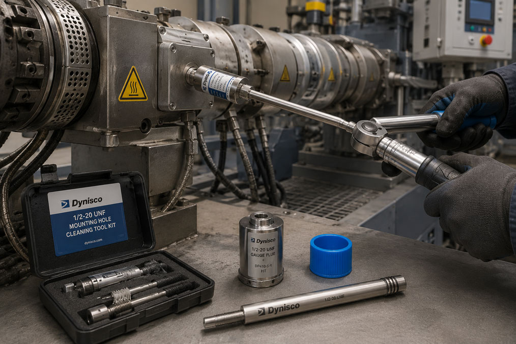
Suitable tool kits should be used for cleaning. A typical kit for a 1/2-20 UNF mounting hole contains tools for the thread, guide section and sealing seat as well as an inspection gauge. During cleaning, the plastic should be soft or semi-molten. This allows it to be removed without unnecessarily changing the geometry of the hole.
The thread section is cleared of residues using the designated tool. The guide sleeve is then screwed in and the cleaning tool is passed through the hole in a controlled manner. The tool must not be tilted sideways or moved back and forth uncontrollably, as this can damage the seat and guide surfaces.
After cleaning, the mounting hole is checked using the inspection gauge. The sensor should only be installed once the gauge contacts the designated sealing seat evenly and no polymer residues remain in the mounting hole.
Cleaning too frequently or too aggressively can also be problematic. If metal is removed from the hole every time a sensor is replaced, the mounting hole may become too deep or too large over time. Cleaning tools are therefore not milling tools for repeated remachining. If dimensional deviations are identified, the hole must be measured correctly and repaired if necessary.
Handling the measuring diaphragm and protective cap correctly
The protective cap on the sensor tip is not unnecessary packaging. It prevents the diaphragm from coming into contact with tools, workbenches or other components during transport, storage and handling.
The protective cap should only be removed immediately before the sensor is inserted into the inspected mounting hole. After removal and permissible cleaning, it should be refitted as soon as the sensor has cooled sufficiently and can be stored safely.
The diaphragm must not be pressed with a finger or touched as part of an assumed functional test. Even a soft object may apply a concentrated force greater than the load the diaphragm experiences during normal operation.
Screwdrivers, knives, scrapers, abrasive paper and rotary tools must not be used to clean the sensor tip. Wire brushes and burning off polymer residues with an open flame are also unsuitable. They may alter the diaphragm mechanically, thermally or chemically.
If the manufacturer permits the tip to be cleaned, the sensor should be removed while the melt is soft and the surface carefully wiped with a non-abrasive cloth. Solvents may only be used if their compatibility with the diaphragm material, coating, seals and polymer has been clearly confirmed.
If plastic is already firmly burnt or carbonised onto the diaphragm, it should not be removed by force. In this case, a technical assessment is preferable to a cleaning attempt that could permanently damage the sensor.
Installing a melt pressure sensor step by step
Before installation begins, the machine must be depressurised, electrically isolated and secured against being switched on again. The system temperature must be controlled so that any polymer present remains sufficiently soft while there is no risk from escaping melt or hot surfaces.
The first step is to check whether the sensor and mounting hole actually match. The model designation, process connection, tip length, pressure range, temperature range and electrical version are compared with the system documentation.
The mounting hole is then cleaned and inspected using a suitable gauge. The thread must be free of damaged flanks, metal chips, corrosion and plastic residues. The sealing seat must not show scoring or one-sided pressure marks.
If specified in the operating instructions, a thin layer of a high-temperature anti-seize compound suitable for the process temperature may be applied to the sensor thread. The compound should only be applied to the designated thread section. The measuring diaphragm and sealing seat must not be contaminated.
The sensor is initially screwed in by hand. It must be possible to guide it to the seat without excessive force. Any resistance that can already be felt during this phase is a warning sign. The sensor must not be forced into a tight or misaligned hole using a spanner.
Final tightening is carried out only at the designated hexagon and with a suitable torque wrench. The electronics housing, electrical connection and transition between stem and housing must not be used for holding or applying torque.
For sensors with a flexible stem or capillary, the permissible minimum bend radius must be observed. The capillary must not be kinked, crushed or installed under tension. The electronics housing should be secured at a low-vibration point with suitable thermal conditions.
After mechanical installation, the electrical connection is made in accordance with the wiring diagram. Cables should be routed separately from high-interference power cables, frequency converters and contactor wiring. Shielding and earthing must be appropriate for the sensor type and system concept.
Using the correct tightening torque
The tightening torque serves two purposes: The sensor must seat securely against the designated sealing surface without being subjected to excessive mechanical stress. Insufficient torque may result in an inadequate seal. Excessive torque may damage the thread and sealing seat, shift the zero point or cause the sensor to seize so that it cannot later be removed without damage.
For common Dynisco models with a 1/2-20 UNF connection, technical information frequently specifies installation torques of approximately 100 to 200 inch-pounds. This corresponds to approximately 11 to 23 Nm. Some operating instructions specify a maximum torque of 500 inch-pounds or approximately 56 Nm for corresponding connections.
These values must not be regarded as general specifications for every melt pressure sensor. The design, sealing seat, diaphragm geometry, thread, anti-seize compound and manufacturer differ. The tightening torque stated in the operating instructions or data sheet for the specific sensor is always decisive.
| Installation situation | Possible effect | Recommended procedure |
|---|---|---|
| Torque too low | Incomplete seating, possible leakage or unstable measurement | Apply the model-specific value using a calibrated torque wrench |
| Torque too high | Mechanical stress, zero-point shift, thread seizure or sensor damage | Do not tighten by feel or using an extension tube |
| Sensor already binds while being screwed in | Incorrect or contaminated thread, off-centre hole | Stop the installation, remove the sensor and inspect the mounting hole |
| Tool applied to the housing | Twisting of the housing or damage to the capillary and electronics | Apply the tool only to the designated hexagon |
| Unsuitable sealing compound used | Changed installation depth, contaminated sealing seat or process contamination | Use only approved anti-seize and lubricating compounds on the designated thread section |
If a sensor has been installed with significantly excessive torque, the seal should not be the only factor considered. The electrical zero point and behaviour during temperature changes may also be affected. A check before production begins is therefore required.
Selecting a suitable installation point on the extruder
The installation point determines which process information the sensor provides and which mechanical loads it is exposed to. Typical measuring points are located in the extruder barrel, upstream of a screen changer, upstream and downstream of a melt pump, in an adapter or immediately upstream of the die.
If the sensor is installed too far upstream, granules that have not yet fully melted may flow past the diaphragm. Hard particles, glass fibres and other fillers can have an abrasive effect on the sensor tip.
A measuring point directly upstream of the screen changer can be used to detect increasing pressure caused by a blocked screen. Downstream of the melt pump or upstream of the die, the pressure actually available to the subsequent process can be assessed.
The sensor must not protrude into the movement area of the extruder screw or other machine components. The design must provide sufficient clearance under all operating conditions, thermal expansion states and possible manufacturing tolerances.
Dead spaces should be avoided. If plastic remains in front of the diaphragm for an extended period, it may thermally degrade. In addition to measurement errors, this can cause discoloration, material deposits or unwanted particles in the final product.
The electronics housing should also not be exposed to unnecessarily high temperatures. A longer rigid stem or flexible capillary can thermally isolate the electronics from the process. Nevertheless, the permissible ambient temperature of the housing must be observed.
Avoiding cold starts and removal with solidified melt
A cold start is particularly critical for both the melt pressure sensor and the extruder. If solidified polymer is present in front of the measuring diaphragm, the sensor is not initially exposed to normal hydrostatic melt pressure when the machine starts. Instead, solid plugs of material and mechanical shear forces may act on the diaphragm.
Before starting, the system must therefore be held at operating temperature for a sufficient period. Not only the heater bands, but also the barrel wall, die, adapter, screen changer and plastic material in dead spaces must be thoroughly heated.
A displayed target temperature does not automatically mean that all of the material has already melted uniformly. The required heating and soaking time depends on the machine size, polymer, fillers, die geometry and preceding shutdown period.
The sensor must also not be removed while the melt is solidified. The system must first be depressurised, switched off and secured against being switched on again. At the same time, the connection area should remain warm enough for the polymer to be soft and not pull on the diaphragm.
If a cold sensor is forcibly unscrewed, adhering material may deform the diaphragm or tear it completely away from the tip. An apparently tight connection must therefore not be loosened using increasingly long levers without first checking the condition of the polymer and thread.
Preventing overpressure and impermissible process loads
Even a correctly installed melt pressure sensor can be damaged if the actual process pressure exceeds the permissible range. Critical situations can be caused by blocked screens, closed valves, obstructed dies, incorrect melt pump control or starting the machine too quickly.
The measuring range should not be selected solely on the basis of the usual production value. Start-up peaks, cleaning cycles, material changes and possible malfunctions must also be considered. A sensor that permanently operates close to the upper limit of its measuring range during normal production has little reserve for dynamic pressure peaks.
The permissible overload capacity is model-specific. It must not be confused with the burst pressure or a permanently permissible operating pressure. Even if a sensor survives a short-term overload without visibly breaking, its zero point may shift or its measuring accuracy may deteriorate permanently.
A smaller measuring range generally improves resolution within the desired process window, but may increase the risk of damage from unpredictable pressure peaks. The selection must therefore achieve a reasonable compromise between measuring accuracy, process resolution and overload reserve.
The sensor does not replace mechanical overpressure protection. Rupture discs, rupture pins, safety shutdowns and other protective measures must be designed independently of the normal process measurement in accordance with the machine and safety concept.
Checking the zero point, output signal and measuring chain
After mechanical installation, the sensor should not immediately be assessed solely on the basis of the displayed pressure value. The mounting position, tightening torque, temperature and mechanical preload may influence the zero point. The zero adjustment or zero-point check specified by the manufacturer is therefore required after installation.
Zeroing may only be carried out under the conditions defined in the manual. It must generally be ensured that no process pressure is present and that the sensor has reached a stable thermal condition. If the sensor is zeroed while residual pressure is present, the entire measuring curve is shifted.
For sensors with an mV/V output, the excitation voltage, cable routing, bridge resistance and input of the display or control instrument must be compatible. Incorrect wiring may cause reversed polarity, an unstable zero point or a missing measuring signal.
Melt pressure transmitters with a 4–20 mA output are integrated directly into a current loop. The supply voltage, load resistance, polarity and PLC scaling must be checked. A sensor with a measuring range of 0 to 500 bar must be scaled differently in the control system from a sensor with a range of 0 to 1,000 bar, even though both provide an output of 4 to 20 mA.
For testing a 4–20 mA signal loop, the UPS4E loop calibrator can be used as a supplementary instrument. It can be used, for example, to measure the actual loop current or simulate a defined signal for the PLC.
However, the UPS4E does not test the mounting hole, measuring diaphragm or physical pressure characteristic of the melt pressure sensor. For mV/V sensors, a test or simulation instrument suitable for strain-gauge bridge signals is also required.
Typical installation errors and their consequences
An installation error does not always result immediately in complete sensor failure. The sensor often continues to operate initially, but provides a shifted or unstable reading. As a result, the cause may incorrectly be suspected in the process control, electronics or polymer.
| Observation | Possible cause | Recommended check |
|---|---|---|
| Zero point is significantly shifted immediately after installation | Excessive tightening torque, stressed seat or lateral load | Check the torque and mounting-hole geometry and assess the sensor without pressure |
| Sensor is difficult to screw in | Contaminated, damaged or incorrect thread | Stop the installation and inspect the thread using a gauge |
| Measured value responds very slowly | Dead space or carbonised polymer in front of the diaphragm | Examine the installation depth and condition of the mounting hole |
| Melt leaks from the connection | Damaged sealing seat, incorrectly machined hole or unsuitable torque | Inspect the sealing seat and sensor connection after safe removal |
| Sensor fails after the machine is started | Cold start, solidified polymer or severe pressure peak | Examine the heating procedure, pressure trend and diaphragm |
| Diaphragm is pressed in | Polymer residue in the hole, tool contact or excessively narrow mounting hole | Measure the complete mounting hole and review the cleaning procedure |
| Sensor tip is sheared off | Excessive projection or contact with the screw or another machine component | Check the installation depth and machine drawing |
| Sensor cannot be removed | Thread seizure, missing anti-seize compound or excessive tightening torque | Check the temperature condition and thread; do not forcefully turn the housing |
If sensor failures recur, a more robust or expensive model should not automatically be installed. The mounting hole, installation point, tightening torque, heating procedure and actual pressure peaks must first be investigated. Replacing the sensor alone does not eliminate a design-related or process-related cause.
Practical example: A new sensor immediately shows a zero-point error
An older melt pressure sensor on an extruder is replaced because of an unstable reading. According to the order, the new sensor has the same pressure range and a 1/2-20 UNF process connection. After it is screwed in, however, the evaluation instrument already displays a clearly positive pressure value while the machine is depressurised.
It is initially suspected that the new sensor has an electrical fault. However, an inspection of the wiring and measuring amplifier reveals no abnormalities. During removal, it becomes apparent that unusually high force is required to loosen the sensor.
A subsequent inspection of the mounting hole using a cleaning tool and inspection gauge shows a hard layer of degraded polymer at the end of the hole. The previous sensor had been positioned slightly farther back. When the new sensor was screwed in, its tip was pressed against the deposit.
In addition, the sensor had been tightened without a torque wrench. A long spanner had been used to overcome the assumed resistance. As a result, the diaphragm was subjected to mechanical loading and the sensor connection was stressed.
After the mounting hole has been cleaned and inspected correctly, an undamaged replacement sensor can first be installed by hand and then tightened to the specified torque. After thermal stabilisation, the zero point is adjusted in accordance with the manufacturer’s instructions. The reading now remains stable while the system is depressurised.
The example illustrates that a matching connection thread alone does not guarantee correct installation. The mounting-hole depth, sealing seat, contamination and tightening torque are equally important.
Assessing damaged sensors correctly
A melt pressure sensor that exhibits abnormal behaviour should first be visually inspected while the system is safe and depressurised. The diaphragm is checked for dents, scratches, bulging or firmly adhering polymer. Damaged thread flanks, discoloration and evidence of one-sided contact may also indicate an unsuitable mounting hole.
The diaphragm must not be subjected to mechanical force during inspection. A visually undamaged diaphragm also does not rule out internal damage. Overpressure, excessive temperature, a kinked capillary or mechanical stress may affect the measuring system without leaving clear external damage.
For a sensor with a significant zero-point shift, it should first be ruled out that residual pressure, incorrect wiring, insufficient warm-up time or unsuitable zero adjustment are responsible. Only then can it be determined whether calibration, a repair assessment or replacement is required.
If the measuring diaphragm is damaged, the sensor must not continue to be used. Depending on the design, a pressure transmission medium may be present inside the sensor. Whether this is mercury, oil, NaK or another medium must be checked using the exact model designation and documentation. A damaged sensor must not be opened or disposed of in an uncontrolled manner.
For a reliable damage analysis, photographs of at least the sensor tip, thread, nameplate and mounting hole should be available. Additional useful information includes the polymer, fillers, process temperature, normal operating pressure, maximum pressure peaks, installation point, tightening torque and the sequence of events immediately before the failure.
Which measuring instruments / products are suitable?
Different Dynisco melt pressure sensors are available for measuring melt pressure in extruders, injection-moulding machines, melt pumps and plastic-processing dies. The selection depends, among other factors, on the pressure range, process temperature, connection thread, output signal, stem length, installation point and required pressure transmission medium.
Sensors with an mV/V output are suitable for applications in which a compatible measuring amplifier, pressure indicator or controller is already available. They provide a direct strain-gauge bridge signal and must be electrically matched to the connected evaluation instrument.
For direct integration into PLC, DCS or process control systems, melt pressure transmitters with an amplified output signal can be used. Versions with a 4–20 mA output are particularly common. Depending on the model, voltage outputs, HART communication or additional temperature measurement may also be available.
If mercury is not permissible or is undesirable as the pressure transmission medium for an application, mercury-free melt pressure sensors can be considered. Final suitability depends on the specific process, temperature, pressure range and regulatory requirements.
An overview of additional sensors, evaluation instruments and solutions for plastics and polymer processing is available in the Dynisco products category.
In addition to the sensor itself, suitable machining, cleaning and inspection tools should also be considered. A correctly machined and regularly inspected mounting hole is often more economical than repeatedly replacing mechanically damaged sensors.
For melt pressure transmitters with a 4–20 mA output, the UPS4E loop calibrator can be used as a supplementary instrument for electrical commissioning and troubleshooting. It tests the current loop and PLC scaling, but does not replace a pressure calibrator or the mechanical inspection of the mounting hole, thread and diaphragm.
ICS Schneider Messtechnik assists with selection on the basis of the existing machine and actual application data. For a replacement instrument, the full model designation of the existing sensor, photographs, dimensional drawings, connection thread, pressure range, output signal, melt temperature and information about the polymer being processed should be provided wherever possible.
Conclusion: A correctly machined mounting hole protects the melt pressure sensor better than any subsequent repair
Melt pressure sensors are designed for high pressures and temperatures in plastics processing. Nevertheless, their measuring diaphragm remains a sensitive precision component. A contaminated, incorrectly machined or excessively deep mounting hole may permanently damage the sensor during installation.
A matching thread alone is not sufficient. The guide bore, sealing seat, installation depth and clearance around the sensor tip must comply with the manufacturer’s drawing. Before every installation, the mounting hole should be cleaned using suitable tools and inspected with a gauge.
The protective cap remains on the sensor until shortly before installation. The sensor is first screwed in by hand and then tightened at the designated hexagon using a torque wrench. The model-specific tightening torque must be neither exceeded nor undercut.
A sufficiently long heating procedure, removal while the melt is soft and the prevention of impermissible pressure peaks are equally important. Observing these fundamental requirements can prevent many typical zero-point errors, diaphragm failures and premature sensor breakdowns.
Frequently asked questions about installing melt pressure sensors
Which threads are used for melt pressure sensors?
A common connection is 1/2-20 UNF. M18 × 1.5, M10 and other manufacturer-specific or application-specific connections are also available. The full model designation and dimensional drawing of the sensor are always decisive.
Can a 1/2-20 UNF sensor be screwed into any matching threaded hole?
No. In addition to the thread, the guide bore, sealing seat, depth and clearance for the sensor tip must be machined correctly. An ordinary threaded hole without the required internal geometry may damage the sensor.
Why does the standard mounting hole often have a 45° seat?
For corresponding sensor designs, the 45° seat forms the defined sealing and contact surface. This positions the sensor at the intended depth and seals the process connection.
How can the mounting hole be inspected?
The most reliable method is to use a suitable inspection gauge or gauge plug. Marking compound can additionally be used to check whether the gauge contacts the intended sealing seat evenly.
Why must the mounting hole be cleaned before every installation?
Hardened polymer residues may press directly against the measuring diaphragm as the sensor is screwed in. Even a small deposit at the end of the hole may deform the diaphragm or position the sensor at an incorrect depth.
Can the mounting hole be cleaned using a conventional drill?
Improvised drills may alter the depth, guide section or sealing surface. Cleaning tools specifically designed for the relevant connection geometry, used with a guide sleeve and followed by inspection with a gauge, are preferable.
At what temperature should the mounting hole be cleaned?
The polymer should be soft or semi-molten so that it can be removed in a controlled manner. The machine must be depressurised, safely shut down and secured against being switched on again.
How is the diaphragm of a melt pressure sensor cleaned?
Only in accordance with the manufacturer’s instructions. Soft polymer may often be removed carefully using a non-abrasive cloth. Scrapers, wire brushes, abrasives and open flames are unsuitable.
Can the measuring diaphragm be checked with a finger?
No. The diaphragm is very thin and must not be pressed in or subjected to a concentrated load. A manual pressure test may already cause permanent deformation.
When should the protective cap be removed?
The protective cap should only be removed immediately before the sensor is inserted into the cleaned and inspected mounting hole. The diaphragm should remain protected during storage and transport.
What tightening torque is required for a 1/2-20 UNF melt pressure sensor?
This depends on the specific model. For common Dynisco designs, values of approximately 100 to 200 inch-pounds or around 11 to 23 Nm are sometimes specified. Some manuals state higher permissible maximum values. Only the documentation for the specific sensor is binding.
Why should the sensor not simply be tightened as firmly as possible?
Excessive torque may damage the thread, stress the sensor, shift the zero point or cause the connection to seize. Additional torque does not improve a defective sealing surface.
Where should the spanner be applied?
Only to the designated hexagon of the process connection. The electronics housing, connector, rigid stem and flexible capillary are not suitable points for applying torque.
Should anti-seize compound be applied to the thread?
If specified in the manufacturer’s instructions, a high-temperature anti-seize compound suitable for the process temperature may be applied thinly to the thread section. The diaphragm and sealing seat must not be contaminated.
Why does a new sensor already indicate pressure after installation?
Possible causes include mechanical stress, excessive tightening torque, polymer residues in the mounting hole, residual pressure in the process or a zero adjustment that has not yet been performed. The wiring and PLC scaling must also be checked.
When may the zero point be adjusted?
Only under the conditions specified by the manufacturer. The sensor must generally be installed correctly, depressurised and thermally stable. Zeroing while residual pressure is present results in an incorrect measuring curve.
Why is a cold start dangerous for the diaphragm?
Solidified polymer can act as a solid body against the diaphragm. During start-up, this produces concentrated forces and shear loads that are significantly more critical than normal, uniformly distributed melt pressure.
Can the sensor be removed from a cold extruder?
This is not recommended. Solid polymer may adhere to the diaphragm and deform or tear it off during removal. The system must be depressurised and secured, but the plastic around the connection should still be sufficiently soft.
What happens if the sensor protrudes too far into the extruder?
The sensor tip may be exposed to unnecessarily severe abrasion or may even come into contact with the screw, mixing elements or other moving components. In an extreme case, the tip may be sheared off.
What happens if the sensor is recessed too far?
A dead space may form in front of the diaphragm. Melt remains there, thermally degrades and may carbonise. This frequently causes slow, damped or drifting readings.
Can a damaged sealing seat be compensated for by tightening the sensor further?
No. A damaged or incorrectly machined sealing seat must be inspected and repaired correctly. Additional torque merely increases the risk of further damage.
How can a mechanically damaged diaphragm be identified?
Possible indications include dents, scratches, a bulged surface, firmly burnt-on deposits, a significant zero-point offset or no pressure response. However, not every internal fault is externally visible.
Can a sensor with a damaged diaphragm continue to be used?
No. The sensor should be taken out of service and assessed on the basis of its specific design. Depending on the model, it may contain an internal pressure transmission medium that requires special handling and disposal procedures.
Can the UPS4E test a melt pressure sensor?
The UPS4E is suitable for testing the electrical 4–20 mA current loop of a corresponding melt pressure transmitter. It can measure the sensor current or simulate a signal for testing the PLC. It does not test the measuring diaphragm, mounting hole or physical pressure measurement.
What information is required when selecting a replacement sensor?
The required information includes at least the previous model designation, pressure range, output signal, process connection, tip and stem length, process temperature, polymer, possible fillers, installation point and electrical terminal assignment. Photographs and dimensional drawings make correct identification easier.